
Diver-based Control of a Tethered Unmanned Underwater Vehicle
Andrew Speers and Michael Jenkin
Computer Science and Engineering, York University, Toronto, Canada
Keywords:
Underwater Robotics, Human-robot Communication.
Abstract:
Human-robot communication with an underwater vehicle is a complex problem. Standard wireless commu-
nication protocols are unavailable, and the lack of direct supervision from surface-based operators reduces
situational awareness and operational efficiencies. Here we describe recent research results with tethered op-
eration of autonomous vehicles at depth by diving operators. We review different operational designs and
describe a novel system based on exploiting advances in lightweight computational platforms (tablet devices)
as the basis of the operator control console. Recent field experiments are also described.
1 INTRODUCTION
Effectivehuman-robotcommunication is essential ev-
erywhere, and nowhere is that more the case than
when communicating with robots that operate un-
derwater. The underwater environment places lim-
its on communication infrastructure and at the same
time the dangerous nature of the environment means
that even simple errors in autonomous operation can
lead to the complete loss of the vehicle. Given this,
the development of effective communication strate-
gies for unmanned underwater vehicles (UUVs) is
critical. Unfortunately not only does the underwa-
ter environment require effective communication be-
tween a robot and its operator(s), it also places sub-
stantive constraints on the ways in which this com-
munication can take place. The water column restricts
many common communication approaches and even
systems that might be appropriate for underwater use
such as ultrasound tend to have low bandwidth and
high power consumption. As a consequence the phys-
ical tether has emerged as a common communication
conduit for human-robot communication underwater.
The most common way of structuring human-
robot communication for autonomous underwater ve-
hicles is from a surface controller via a physical tether
to an underwater vessel that is not directly visible to
the operator (see (Nokin, 1994), (Lee et al., 2000),
(Aoki et al., 1997) and Figure 1). While such an ap-
proach can provide for excellent communication be-
tween the operator and the device as well as providing
a conduit for power and vehicle recovery if necessary,
a tether, and in particular a surface-based tether also
presents several problems. The operator is typically
located in some safe, dry location (as shown in Fig-
ure 1(a)). The operator has no direct view of the au-
tonomous vehicle. Furthermore it is typically the case
that the operator’s only “view” of the operational en-
vironment is via sensors mounted on-board the plat-
form. As a consequence the operator tends to have
very poor situational awareness.
The actual UUV operator is, of course, not the
only human involved in controlling an underwater ve-
hicle. Although a tether provides a number of advan-
tages, at the end of the day it is a tether that must
be properly managed. Different deployments neces-
sitate different tether strategies but personnel must be
deployed in order to deal with the tether. Figure 1(b)
illustrates the complexity of this problem for the shore
deploymentof an underwatersensor package. A num-
ber of personnel are engaged in the task and the abil-
ity of the various personnel to communicate among
each other effectively is key to successful UUV de-
ployment.
The vast majority of UUVs operate on their own.
In contrast, the AQUA platform (Dudek et al., 2005)
(see Figure 2) is a UUV that is designed to operate
with humans in close proximity. This property gener-
ates a number of interesting constraints and opportu-
nities with respect to operating the robot with a tether.
In order to ensure that the robot operates safely in the
presence of other humans (divers) in the environment
it is desirable to place the human operator underwa-
ter, rather than on the surface as depicted in Figure 1.
When operated in this configuration the operator has
an enhanced view of the work-site as well as any other
200
Speers A. and Jenkin M..
Diver-based Control of a Tethered Unmanned Underwater Vehicle.
DOI: 10.5220/0004457102000206
In Proceedings of the 10th International Conference on Informatics in Control, Automation and Robotics (ICINCO-2013), pages 200-206
ISBN: 978-989-8565-71-6
Copyright
c
2013 SCITEPRESS (Science and Technology Publications, Lda.)
(a) (b)
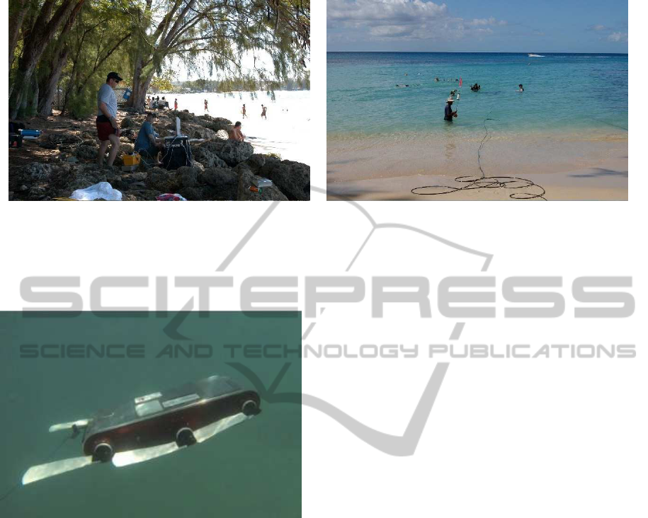
Figure 1: The realities of surface-based tethering. Here surface-based operators (a) communicate with a submerged device
(b) through a tether. Note that the operators do not have direct view of the device, nor can they see any divers who might be
accompanying the device at depth. For this deployment also observe the large number of cable handlers required to service
the cable as it travels through the surf zone.
Figure 2: KROY, one of the members of the AQUA family
of robots operating at depth. KROY is a swimming hexa-
pod. Each of the six fins can be controlled independently.
divers in the vicinity. Furthermore, it is possible to
position tether wranglers at depth and for the opera-
tor to have a line of sight with the various personnel
involved in the deployment.
Although this operational mode can provide a sub-
stantive enhancement to the operator’s ability to con-
trol the vehicle and generally enhance the situational
awareness of the operator, it is now necessary to con-
struct an operator interface that can function at depth.
The classic keyboard, computer and mouse found in
Figure 1(a) is neither waterproof nor capable of with-
standing the pressures encountered within the diver-
operator’s operational range.
The problem of migrating a UUV operator’s in-
terface to an underwater platform was considered in
(Verzijlenberg and Jenkin, 2010). In this work stan-
dard tablet PC’s were mounted within water tight
and pressure resistant housings (see Figure 3). The
surface-based user interface was adapted to take input
commands from a collection of buttons mounted on
the sides of the housing (see Figure 3) but besides this
the basic GUI was left unchanged. Power for the other
components contained in the housing were either pro-
vided by drawing power through the USB-ports of
the laptop or through small USB-batteries that pro-
vide 5V. The devices were designed to have approx-
imately 60 minutes of operation once sealed, a time
that was consistent with the operational regime of the
robot once deployed. The housings were augmented
through the addition of an IMU that allowed the en-
tire tablet to be treated as an underwater joystick and
the operator could command the pitch/yaw/roll of the
vehicle through the orientation of the tablet relative to
gravity.
In total three different generations of these tablets
were constructed (the second and third generation
versions are shown in Figure 3). Tests with the
AQUATablet were very successful (see (Verzijlenberg
and Jenkin, 2010) and (Speers et al., 2011) for details)
but a number of issues were identified when operating
the robot at depth.
• The form factor of the PC requires that the hous-
ing be relatively large. Although the waterproof
container can be machined to be relatively light
when empty, it is critical that this container be
(approximately) neutrally buoyant when deployed
underwater. (If it is not neutrally buoyant then
the diver-operator will have to compensate for this
when operating the device). In order for the entire
tablet to be neutrally buoyant it must weigh the
same as the weight of the water it displaces. Thus
the relatively large volume of the tablet housings
requires that the tablets be weighted through the
Diver-basedControlofaTetheredUnmannedUnderwaterVehicle
201
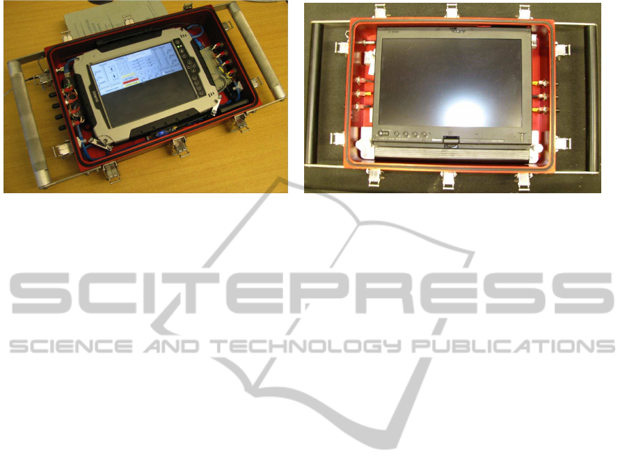
(a) 2nd generation. (b) 3rd generation.
Figure 3: PC tablet-based AQUATablets. These two versions of the AQUATablet are based around tablet PC’s. The PC
provides computing and network support. A collection of water-proof switches on the sides of the housing provide basic
input. A GUI provides visual output to the user. Housed within the tablets are an Arduino that interfaces with the switches
and an IMU that allows the entire tablet to be treated like a joystick. When operating at depth a clear plastic cover is secured
over the front of the display. The robot is tethered via a fiber optic tether. A transducer between the PC’s Ethernet port and
the optical fiber connection is also housed within the case.
addition of external mass. This makes traveling
with the tablets before deployment more difficult,
but it also means that the tablets have a large mo-
ment of inertia. They may be “weight-less” un-
derwater, but they are still difficult to move. This
makes using the entire tablet as a joystick more
difficult.
• The tablet housings have a reasonably large sur-
face area. This means that when operated in a
strong current or swell the tablet case acts as a
drag or sail on the operator.
• The use of a tablet PC increases the cost of the
components inside the waterproof housing. The
unfortunate reality of underwater robotics projects
is that there is always the potential for water to
penetrate the housing with disastrous results for
the electronics (especially in salt water). One rea-
son for the increased cost associated with PC-
based electronics is that the process of monitor-
ing the physical switches and the IMU requires
special purpose electronics that are not normally
found on tablet PC’s.
When work began on the original AQUATablet
there were very few options in terms of obtaining the
necessary computational power in a tablet-like form
factor. Recent advances in tablet technology now
make the necessary display, connectivity, and com-
putational power readily available in a lightweight,
small form factor package. Here we describe an up-
dated version of the AQUATablet based around an
Android-based ASUS Nexus 7 tablet. In addition
to providing the necessary control inputs to commu-
nicate with the UUV, the Nexus 7 includes WiFi,
GPS and accelerometer sensors which reduces sub-
stantively the cost of the components and the size of
the revised “lightweight” AQUATablet.
2 A LIGHTWEIGHT
AQUATABLET
The lightweight AQUATablet is shown in Figure 5.
As with the earlier designs of the AQUATablet the
housing is essentially a waterproof box designed to
withstand the pressures associated with an operator-
diver operating the vehicle at 100’. (Note that the
robot can descend below the diver, but that given the
limits associated with diving on air, 100’ is a reason-
able constraint on the anticipated maximum depth for
the operator tablet.) Whereas the housings for the
AquaTablet 2 and 3 shown in Figure 3 were milled
from aluminum, it was possible to mill the lightweight
AQUATablet from Plexiglas given its smaller dimen-
sions.
As with the earlier models the AQUATablet is
equipped with a small number of switches (now two)
with which the user can interact with the housing. (As
the tablet is operated inside a sealed housing it is not
possible to interact with the tablet through its surface,
as would normally be the case.) The housing itself
contains the following:
• An ASUS Nexus 7 which is self contained for
power, and which provides display, computation
and a number of sensors and communications op-
tions (including WiFi). The Nexus 7’s only phys-
ical connection is a USB port.
ICINCO2013-10thInternationalConferenceonInformaticsinControl,AutomationandRobotics
202
• The USB on the Nexus 7 is connected (via a
small powered USB hub) to a Phidgets interface
board which provides connectivity to the external
switches, and an Ethernet adaptor that connects to
the external fiber connection to the robot.
• A small battery pack provides power to the USB
hub and network hardware.
2.1 Software Infrastructure
Earlier versions of the AQUATablet utilized a modi-
fied version of the GUI software used by a standard
PC when controlling the UUV. The decision to move
to an Android-based tablet necessitated a change in
the underlying software infrastructure.
The AQUA robot platforms wrap the underlying
Robodevel infrastructure within a network of Robot
Operating System (ROS) (Quigley et al., 2009) nodes.
Within ROS overall robot control is modeled as a col-
lection of asynchronous processes that communicate
by message passing. Although a very limited level of
support does exist for ROS on the Android platform,
it is not a fully supported environment for ROS. In
order to avoid any potential inconsistencies between
the Android-ROSimplementation and supported ROS
environments, it was decided to not build the software
structures on the Android platform in ROS directly,
but rather to exploit the
rosbridge
(Brown Univer-
sity, 2013) mechanism instead.
rosbridge
provides a
mechanism within which ROS messages are exposed
to an external agent and within which an external
agent can inject ROS messages into the ROS envi-
ronment. This injection process uses the
WebSocket
(Hickson, 2010) protocol which means that provided
the external agent has network access to the ROS en-
vironment it can be physically located anywhere.
Within ROS messages are passed using an inter-
nal protocol. The
rosbridge
framework communi-
cates these messages to and from the external world
in the form of
yaml
(Yet Another Markup Language)
strings. Such yaml strings can be used directly by an
external agent but perhaps the most convenient way is
to use
json
(Corckford, 2006) to map yaml strings to
instances of objects in the environment of the exter-
nal agent. This approach has a number of advantages
in terms of interfacing a lightweight device such as an
Android tablet to a robot running ROS. First, standard
libraries exist that support the
WebSocket
protocol on
the Android device (e.g., (Tavendo, 2013)) and native
support for
json
exists for many platforms including
the Android.
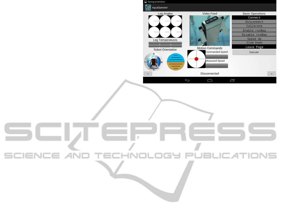
Figure 4: The lightweight AquaTablet user display. The
user interacts with the device through tilting the device and
also through two two-way switches mounted on the side of
the housing. Pitch and roll of the device are used to control
the pitch and heading of the robot. See text for details.
2.2 User Interface
One issue with the development of user interfaces
to be operated underwater is the limited options for
human-machine interaction. Standard devices such
as keyboards, mice and touch screen surfaces are not
practical underwater. For example, even though the
touch sensitive surface of devices such as the Nexus
7 and the iPad can be waterproofed the pressure of
the water column causes the entire surface to register
a touch event at relatively shallow depths. As a con-
sequence most interactions are limited to waterproof
switches and sliders that expose some physical com-
ponent to the external environment and then transfer
the event in to the pressurized housing. A wide range
of physical interaction devices exist – often developed
for the underwater camera housing market – as well
as standard electrical switches which was the design
decision made here.
The decision to limit the number of input switches
was made both from practical constraints as well as
experience with the previous AquaTablets. The re-
duced physical size of the lightweight AquaTablet re-
duces the potential locations for switch placement.
Furthermore, each switch increases the potential for
water penetration of the housing. Beyond these phys-
ical constraints, experiments conducted with previ-
ous AquaTablets (which had as many as eight two-
position switches) demonstrated that the cognitive
loading associated with operating a vehicle was not
well served by providing the operator with a multitude
of input switches. It was just too easy for an operator-
diver to forget the intent of the various switches, and
that diving glovesmade it easy for divers to press mul-
tiple switches.
Located on the side of the tablet housing are two
Diver-basedControlofaTetheredUnmannedUnderwaterVehicle
203
(a) (b)
(c) (d)
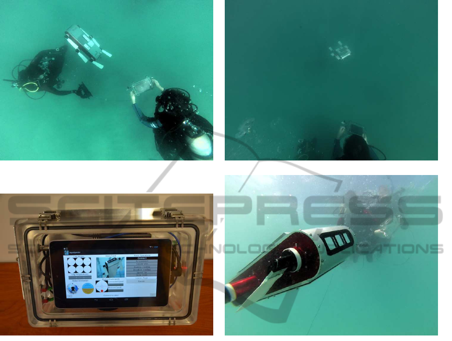
Figure 5: The lightweight computer-based underwater tablet. By utilizing a smaller footprint device it is possible to reduce
substantively the mass/volume of the operator console. (a), (b) and (d) show an underwater operator teleoperating the vehicle.
As can be seen the device is now sufficiently small and lightweight that it can be easily carried by the diver. The device itself
(shown in (c)) is essentially an Android tablet (the ASUS Nexus 7) with external devices to connect to switches on the outside
of the housing and to the optical fiber tether that connects to the robot.
two-way switches. This provides the potential for
four “button press” like events. Lightweight devices
such as the Android have user interfaces that are in-
tended for much more sophisticated inputs (e.g., mul-
tiple touches over their display surface) and thus it
was necessary to construct an input strategy that was
appropriate for the limited set of input events avail-
able.
The primary user display is shown in Figure 4.
The display is broken down into three columns. The
left most column shows instantaneous leg angles and
leg temperatures providing a snapshot of the current
state of the low level systems on the vehicle. Below
this the current heading and pose of the vehicle are
displayed via a compass and an artificial horizon.
The center panel shows a live video feed from the
robot (in Figure 4 the live video feed is simulated by
a static image), followed by the current commanded
speed of the vehicle and the orientation of tablet hous-
ing relative to gravity (indicated by the red circle in
the center of the display). Experiments with the pre-
vious AquaTablets demonstrated that it is very easy
for a diver to make incorrect judgments of the true
vertical given the lack of obvious landmarks to verti-
cal underwater. (See (Jenkin et al., 2009) for details
on quantifying a diver’s ability to perceive the verti-
cal when suspended in water.) Housing tilt is yoked to
changes in intended vehicle depth while housing roll
is yoked to changes in intended vehicle yaw.
The right panel shows a set of potential inputs.
Given the switch-based input paradigm it is not possi-
ble for the operator to just “choose” an input by press-
ing on it. Rather the operator cycles through the var-
ious active buttons using one of the switches while
one of the positions of the second switch causes the
current button to be executed.
ICINCO2013-10thInternationalConferenceonInformaticsinControl,AutomationandRobotics
204

The lightweight AquaTablet is shown in operation in
Figure 5. Figures 5(a) and (b) provide a sense of scale
of the tablet in operation and the reduced size/weight
of the tablet relative to the earlier tablet designs is
clear. The reduced mass/volume of the tablet in par-
ticular makes the device much easier to deploy and
use than the previous versions of the device.
Figure 5(c) shows the Nexus 7 mounted inside the
housing with all of the associated cables, connectors
and power supply. The entire device is not that much
wider and taller than the Nexus itself as can be seen,
although it is about 2” deep. In order to make the en-
tire device more easily operated by a diver the hous-
ing is attached to a base that is slightly larger than the
housing. This provides a shield for the switches to
reduce the possibility that they might be flicked acci-
dentally and a mounting point for a safety line so that
the housing is not lost if it is dropped by a diver.
3 EXPERIMENTAL VALIDATION
The lightweight AquaTablet has undergone extensive
sea trials off the coast of Holetown, Barbados. When
controlled by the tablet the robot is normally operated
by a three person team. A cable wrangler deals with
spooling and unspooling cable to the robot, an oper-
ator controls the tablet and a third team member acts
as a safety diver/videographer.
The reduced volume/mass/surface area of the
tablet relative to the earlier versions of the device was
found to be of particular benefit. As can be seen from
Figure 5 the form factor of the lightweight AquaT-
ablet makes operation very straightforward. The de-
vice can be held quite easily by a diver operator with-
out interfering with the diver’s ability to maintain
their position/orientation within the water column and
indeed to swim near the robot when it is operating.
Having a direct line of sight to the vehicle makes
it substantively easier to operate than when operated
from above the surface. The choice of a limited num-
ber of input switches was also found to be effective
as this reduced the potential for the diver operator to
have to “hunt” for the right input. The reduced visi-
bility available underwater – including fogging of the
operator’s goggles – means that it is difficult to la-
bel the various switches in a meaningful way and the
reduced number of switches actually reduces the po-
tential for confusion.
Although the vehicle state display was useful
when initially launching the vehicle it was found that
during nominal operation such displays were essen-
tially ignored and that for nominal operation a larger
video display feed might be more appropriate.
4 DISCUSSION AND FUTURE
WORK
Although the choice of the Nexus 7 as the display-
compute unit enabled the construction of a smaller
underwater tablet, the decision did have significant
implications in terms of hardware and software. It
was decided in the project to utilize an “un-rooted”
(aka stock) Android tablet. This reduced the options
for various pieces of external hardware as they must
function “out of the box” with the Android. Of par-
ticular importance here is the limited availability of
USB-Gigabit Ethernet adapters that are supported on
the Android.
From a software point of view the Android plat-
form provides substantively less computing power
and memory than the PC-based tablets used previ-
ously. As such certain decisions in terms of the
software infrastructure had substantive implications
in terms of overall system functionality. By default,
rosbridge
will send every message it receives to an
external agent. The limited processing power of the
Android can make servicing all of these messages
problematic. Throttling messages prior to exporting
them via
rosbridge
may be appropriate or necessary.
A more subtle issue related to the use of the
rosbridge
-WebSockets-yaml-JSON pipeline is the
large number of String objects that are created in the
process. Although this is not normally an issue in PC-
based implementations, Android processes must op-
erate within a very limited memory footprint. Mini-
mizing the size of the String’s being processed and the
number of String objects that are created is important
in order to ensure liveliness in terms of the user inter-
face. This problem becomes most acute when images
are transferred through yaml. yaml is a printable en-
coding which means binary data such as images must
be encoded as printable characters. This means that
the “raw” yaml message is extremely large. This mes-
sage must then be decoded into an image (another
large structure on an Android platform) which must
be further drawn onto internal structures within the
Android in order to display them. Although it is cer-
tainly possible to send an image stream encoded as
yaml messages to an Android platform, it is not nec-
essarily the best way given the memory and network
bandwidth constraints involved.
The lightweight AquaTablet was designed to be
sufficiently small that it can be mounted on top of the
robot directly. In this configuration the device can act
as an external display for operators swimming near
the robot, as well as providing GPS information and
WiFi communication when the robot is at the sur-
face. The choice of
rosbridge
as the communica-
Diver-basedControlofaTetheredUnmannedUnderwaterVehicle
205

tion mechanism here allows information to be easily
passed from the robot to off-board agents also operat-
ing within their own ROS environments.
ACKNOWLEDGEMENTS
The technical and diving assistance of Jim Zacher
and Heather Jenkin is gratefully acknowledged. This
project would not have been possible without the gen-
erous financial support of NSERC Canada and the
NSERC Canadian Field Robotics Network (NCFRN).
REFERENCES
Aoki, T., Maruashima, T., Asao, Y., Nakae, T., and Yam-
aguchi, M. (1997). Development of high-speed data
transmission equipment for the full-depth remotely
operated vehicle – KAIKO. In OCEANS ’97, vol-
ume 1, pages 87–92.
Brown University (2013). rosbridge. http://www.rosbridge
.org. Accessed February 10, 2013.
Corckford, D. (2006). The application/json media type for
JavaScript object notation JSON. Netowrk Working
Group RFC 4627.
Dudek, G., Jenkin, M., Prahacs, C., Hogue, A., Sattar, J.,
German, A., Liu, H., Saunderson, S., Ripsman, A.,
Sinhon, S., Torres, L., Milios, E., Zhang, P., and Rek-
leitis, I. (2005). A visually gudied swimming robot. In
IEEE/RSJ Int. Conf. on Intelligent Robots and Systems
(IROS), pages 1749–1754.
Hickson, I. (2010). The WebSocket API. W3C Working
Draft 16 August 2010.
Jenkin, H. L., Zacher, J. E., Dyde, R. T., Harris, L. R.,
and Jenkin, M. (2009). How do SCUBA divers know
which way is up? the influence of buoyancy on orien-
tation judgements. J. of Vision, 9(716):716a.
Lee, P., Jeon, B., Hong, S., Lim, Y., Lee, C., Park, J., and
Lee, C. (2000). System design of an ROV with ma-
nipulators and adaptive control if it. In 2000 Interna-
tional Symposium on Underwater Technology, pages
431–436.
Nokin, M. (1994). ROV 6000 – objectives and description.
In OCEANS ’94, volume 2, pages 505–509.
Quigley, M., Gerkey, B., Conley, K., Faust, J., Foote, T.,
Leibs, J., Berger, E., Wheeler, R., and Ng, A. Y.
(2009). ROS: an open-source robot operating system.
In Proc. Open-Source Software workshop at the In-
ternational Conference on Robotics and Automation
(ICRA).
Speers, A., Topol, A., Zacher, J., Codd-Downey, R., Verzi-
jlenberg, B., and Jenkin, M. R. M. (2011). Monitoring
Underwater Sensors with an Amphibious Robot. In
Proceedings of 2011 Canadian Conference on Com-
puter and Robot Vision (CRV)., pages 153–159, St.
John’s, Nefwoundland.
Tavendo (2013). Autobahn websocket. http://autobahn.ws.
Accessed February 10, 2013.
Verzijlenberg, B. and Jenkin, M. (2010). Swimming with
robots: human robot commuication at depth. In
IEEE/RSJ Int. Conf. on Intelligent Robots and Systems
(IROS), Taiwan.
ICINCO2013-10thInternationalConferenceonInformaticsinControl,AutomationandRobotics
206
