
Three Dimensional Localisation in Underwater Swarms
through a Kalman Approach
Fabio Fratichini
1,2
, Stefano Chiesa
1
and Sergio Taraglio
1
1
Robotics Lab, ENEA, Via Anguillarese 301, Rome, Italy
2
Dipartimento di Informatica ed Automazione, University of Roma Tre, Via Ostiense 159, Rome, Italy
Keywords: Distributed Control Systems, Mobile Robots and Intelligent Autonomous Systems, Space and Underwater
Robots, Sensor Fusion.
Abstract: A three dimensional localisation algorithm for a swarm of underwater vehicles is presented. The proposed
approach is grounded on an extended Kalman filter (EKF) scheme used to fuse some proprioceptive data
such as the vessel’s speed and some esteroceptive measurement such as the time of flight (TOF) sonar
distance of the companion vessels. The results of several simulations are presented. Some considerations
about the available underwater bandwidth and the communication needed by the approach are discussed.
1 INTRODUCTION
The exploration of the oceans both for scientific and
economic purposes is becoming more and more
important. Out of the limitations of our biological
characteristics, underwater robotics has gained an
essential role in the study and exploitation of the
seas. Its more promising branch is that of the
autonomous underwater vehicles (AUV), i.e. those
vehicles that are capable of performing the required
tasks without human supervision, coping with the
mission unknowns.
In the latest years the research on AUVs has
broadened towards the simultaneous use of more
vessels, i.e. the implementation of multi robot
configurations all the way to full swarms of
underwater vehicles.
Whether a single or more AUVs are considered,
one of the focal points of autonomy is the reliable
knowledge of the vessel position and orientation.
Unfortunately an underwater system suffers because
of the limiting characteristics of its environment.
Water, especially salted one, blocks electromagnetic
waves, inhibiting the use of positioning systems
such as the GPS. At the same time this implies a
difficult communication between an AUV and
another or a remote operator. The available means to
localise a single AUV are thus the exploitement of
inertial sensors, velocity ones and/or gyroscopes
combined in dead reckoning.
However, in the framework of an underwater swarm,
the localisation of a single vehicle can profit from
the gathering of information pertaining to the other
fellow vessels. The key issue of all the swarm
localisation methods is the best possible
combination of proprioceptive measures (dead
reckoning) and exteroceptive sensor readings, the
main difference being the employed estimator. The
localisation of swarms of robots has been
extensively studied for packs of terrestial surface
robots. In this case it is possible to use GPS, if
outdoors, or different methods for indoor teams. In
addition the communication of information among
the robots is unproblematic over the radio link.
An approach is based on the subdivision of the
swarm in subgroups one of which, in turn, is kept at
a fixed position and acts as a set of landmarks for the
moving others (Kurazume et al., 1994, 1996) and
(Rekleitis et al., 2002). (Fox et al., 1999; Fox et al.,
2000) and (Thrun et al., 2000) have successfully
employed belief functions combined with a
Montecarlo approach and particle filtetring
optimization. The work of (Roumeliotis, 2000) and
(Roumeliotis and Bekey, 2002) employs a Kalman
filter where the proprioceptive measures are used to
estimate the future state of the system and the
exteroceptive ones are used to correct and update the
estimate. In (Martinelli et al., 2005) this approach is
extended by considering the most generic relative
observations between two robots. More recently the
work of Olfati-Saber, see e.g. (Olfati-Saber, 2007),
215
Fratichini F., Chiesa S. and Taraglio S..
Three Dimensional Localisation in Underwater Swarms through a Kalman Approach.
DOI: 10.5220/0004457502150221
In Proceedings of the 10th International Conference on Informatics in Control, Automation and Robotics (ICINCO-2013), pages 215-221
ISBN: 978-989-8565-71-6
Copyright
c
2013 SCITEPRESS (Science and Technology Publications, Lda.)

has addressed the problem of decentralized Kalman
filtering in sensor networks through consensus
algorithms for the swarm controlling strategies.
(Huang et al., 2011) have investigated the
consistency of EKF based cooperative localisation
considering observability. The typical operative
environment considered in these works is a two
dimensional terrestrial one.
In the following a three dimensional algorithm
for the global positioning of a swarm of underwater
robots is presented, the problem addressed is not that
of swarm control, but the mutual and absolute
positioning of elements composing an underwater
group of robots. A simple kinematic model of the
AUV is considered, capable of measuring its own
velocity and to communicate over an ultrasonic
acoustic link with the other vessels. Through the
measurement of the time of flight (TOF) of the
ultrasound transmission the AUVs can measure one
another their relative distance. All the available
information is then combined with an extended
Kalman filter distributed among the vessels.
In the second section of the paper the problem is
stated in a three dimensional environment. In the
third section the multi robot Kalman based algorithm
is described. In the fourth section some experimental
results are presented relative to different swarm
trajectories. In the fifth section some consideration
on the presented algorithm are discussed especially
concerning the communication issues and the swarm
size.
2 PROBLEM STATEMENT
The key point for a cooperative localisation in a
swarm of robots is viewing the group as a single
entity that can access the information of a large
number of proprioceptive and exteroceptive sensors.
In the following all the vessels are described by
the same motion equations and each robot possesses
proprioreceptive sensors for the motion estimate.
Each AUV possesses also an ultrasound
communication link, which can collect the
information from the other vessels in the swarm
(among these the transmitter ID and the
communication starting time) and through the TOF
measure the estimated inter vessel distance. The
measurement noise is considered as Gaussian.
At first the localisation has been tackled
considering as available the relative position and
orientation measurements, this is helpful to check
the overall reliability of the framework development.
In a second phase only the relative distances and the
absolute values of depth and heading has been
considered, this second case being similar to the
actual underwater conditions. As above described
the relative distance can be easily measured with the
sonar communication while heading can be read
from the compass and depth from a pressure gauge
on board the vessels.
Let us consider the global dynamical state X of
the whole swarm, it will be a vector composed of
MxN items where M is the number of robots and N is
the number of variables describing the single
vehicle, i.e. a vector composed of the poses
i
x
of all
the robots.
],...,
2
,
1
[
M
xxxX
(1)
The mathematical model describing the time
evolution of the single vessel of the swarm is:
,...,M ik
i
w,k
i
u,k
i
xfk
i
x 1111
(2)
where f is generally a non linear function of the state
at the preceding time step
1k
i
x
, of the input
ku
i
and of the noise
kw
i
. The vessels can also measure
all the other ones and this can be described by the:
,, 1, zk hxk x k nk i ,...,Mj i
iiji
(3)
here h is the measurement function linking the state
of the i-th robot with the state of the measured one
(the j-th) and the measure noise
kn
i
.
Figure 1: The coordinate system.
An extended Kalman filter estimates the state of
this dynamical system fusing data coming from
proprioceptive sensors and exteroceptive ones. The
proprioceptive sensors are used to compute the
kinematic time evolution of the system and the
esteroceptive to reset periodically the time evolution
estimate with an external ground truth.
The vessel coordinate system is centred in the
centre of the vehicle and its x axis is longitudinally
directed from stern to bow, the y axis is towards
starboard and the z one downward, see Figure 1.
The kinematic model of the single robot uses a
linear velocity parallel to the x axis (thrust) and the
ICINCO2013-10thInternationalConferenceonInformaticsinControl,AutomationandRobotics
216

possibility to change all the three Euler angles
through appropriate angular velocities.
3 MULTI-ROBOT KALMAN
LOCALIZATION
The Kalman filtering is a well known strategy that
yields an estimate of a dynamical process using a
feedback control. It foresee the process state at a
given time and it employs a measurement feedback
to update the state through a better estimate. It is an
iterative process that loops through two different
phases: on one side it predicts the state of the system
and the error covariance, on the other it computes
the so called Kalman gain to correct both the state
estimate and the error covariance on the grounds of
some kind of measure. Since the time evolution
function (equation 2) may be not linear, an extended
version of the filter has been here employed. The
EKF basically behaves as the standard procedure but
uses a local linearization of the functions. A very
interesting characteristic of this filter is its iterative
aspect. The results of a iteration of the filter is used
as input for the successive step; in this way the filter
retains memory of the history of the system.
Let us consider the whole swarm, the EKF cycles
between the two phases of prediction and update.
3.1 Prediction
Each robot, at a given time step, estimates its state at
the successive time step on the grounds of the
kinematic model and the available proprioceptive
measures (linear and angular velocities) and their
null average Gaussian noise.
))(),(),(
ˆ
()1(
ˆ
kwkukxfkx
iiii
(4)
ˆˆ
(1) ()()() ()()()
TT
ii i ii i i i i
P
kkPkkGkWkGk
(5)
)()(
ˆ
)()1(
ˆ
kkPkkP
T
jijiij
(6)
here equation (4) is the state time evolution and
equations (5) and (6) describe the time evolution of
the cross correlation matrix P in the diagonal and off
diagonal terms;
is the system propagation matrix,
G is the system noise input matrix and W is the noise
input covariance. The minus sign stands for a priori
and the plus one for a posteriori.
In order to perform a distributed EKF it is
convenient to process the a posteriori estimated
cross correlation matrix (equation 6) through a
singular value decomposition (SVD). In this way
each robot can compute its own term multiplying the
SVD term by its dynamical matrix, see (Roumeliotis
and Bekey, 2002).
3.2 Update
Every time a robot measures something, an update
can be performed. The here considered measures are
the heading (compass) and the depth (pressure
gauge) of the measuring vessel and the TOF distance
of another vessel. The non linear measuring function
h is shown in equation (3) and the noise is a null
average Gaussian one. It is now possible to compute
the a posteriori state estimate
1
)()(
ˆ
)()(
ˆ
)(
))
ˆ
,
ˆ
()()(()(
ˆ
)(
ˆ
SkHkPkHkPkK
xxhkzkKkxkx
T
jrj
T
irir
jiirrr
(7)
where the index r describes the vessel
Mr ,...,1
,
)(kK
r
is the so called Kalman gain with S the
residual covariance, and the last term is the residual.
The H terms are the Jacobians of the measuring
function h w.r.t. the two state vectors
i
x
and
j
x
:
100000
000100
000
222
r
z
r
y
r
x
H
i
(8)
000000
000000
000
222
r
z
r
y
r
x
H
j
(9)
and
2222
zyxr
.
Finally the a posteriori covariance matrix
estimate is:
1
ˆˆ ˆ ˆ ˆ ˆ
()()
TT
rs rs ri i rj j i is j js
P
PPHPHSHPHP
(10)
with the indexes
Mr ,...,1
and
Ms ,...,1
.
The problem of the localization of multiple
robots can be approached in two different ways: in a
centralised or in a distributed way. In the first there
is a central supervisor collecting all the data from all
the vehicles and performing the multi robot system
state estimation. The second paradigm can be split
into two further classes: uncooperative or
cooperative algorithms. The first class simply tries
to localise each robot as if it was alone in the world,
i.e. counting on its own estimate and measures
alone, without gathering further information from
the others in the swarm. The second class can
ThreeDimensionalLocalisationinUnderwaterSwarmsthroughaKalmanApproach
217
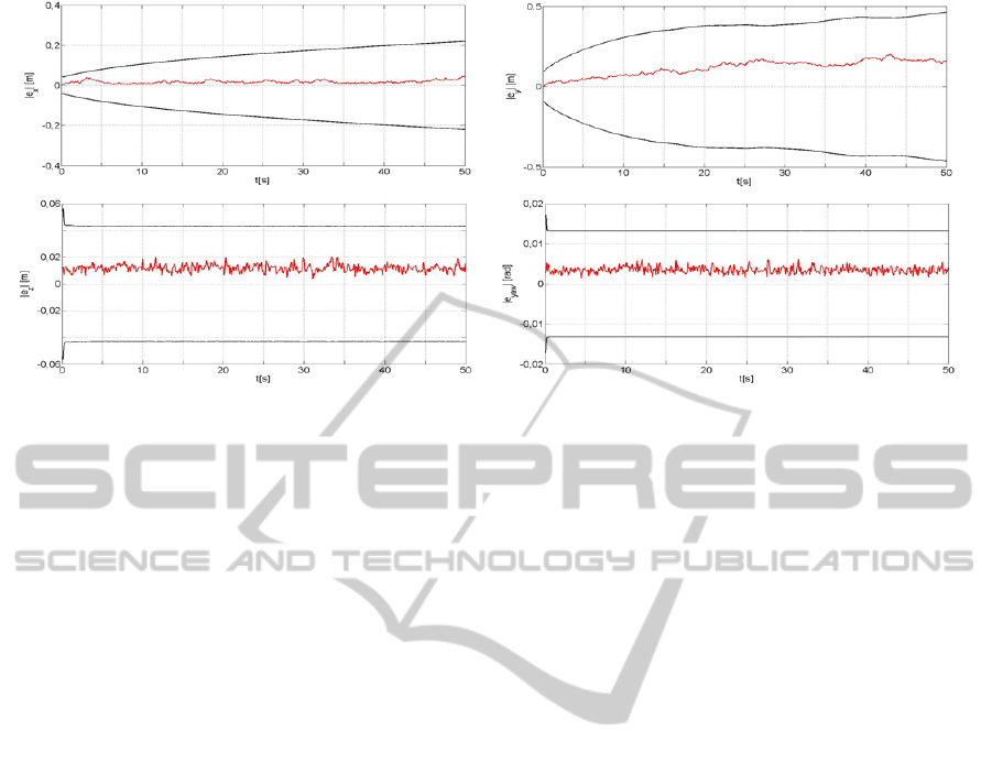
Figure 2: Average and 3σ error for x, y, z and yaw as a function of time, linear trajectories.
exploit the information coming from the companions
and performing a local algorithm for the pose
estimation.
Regardless of the employed approach the basic
issue is the extremely limited bandwidth that is
available underwater. Two or more AUV can
communicate one another through different means,
but the only one that allows long distance data
exchange is the ultrasound transducer. Naturally
there is a trade off between bandwidth and distance
travelled by the ultrasound wave. All this points to a
severe limitation on data circulation among the
swarm vessels. In other words transmissions should
be kept to a minimum with respect to the algorithm
performance.
Unfortunately the Kalman approach needs to
distribute a large quantity of data. In order to limit
the communication problem in the swarm a
distributed-centralized approach has been tested.
The idea is as follows. Whenever a measurement is
done, the measuring robot performs the EKF for the
whole swarm, gathering the states from all the
vessels and broadcasting the new matrices to the
companions. It is obviously a centralised algorithm
but it is distributed in time, at each time step only
the measuring robot is computing, and at the next
time step it will probably be a different one.
This scheme may limit the communication
among the swarm members. The amount of
exchanged data will be the same of a fully
centralized approach, but since only one robot is
actually broadcasting its results, there will be much
less problems arising from the communication
overheads and possible multipaths deriving from
multiple robots trying to communicate all at the
same time.
4 EXPERIMENTAL RESULTS
In the experiments, the vehicles are considered as
kinematic objects, i.e. without the computation of
their dynamics, and are able to exchange
information instantaneously. All the simulations
have been performed under Matlab. A first series of
2D simulations have been carried out to assess the
overall correctness of the algorithm implementation.
In the 3D algorithm version the due kinematic
model has been considered and a more realistic suite
of sensors for the single vessel has been considered
as well. As said, each AUV is equipped, besides the
sonar for communication and distance estimation,
with a compass for the absolute orientation and a
pressure gauge for the depth measure (z coordinate).
The introduction of these sensors and data are of
basic importance since they improve the
observability of the system. In a three dimensional
environment each vessel possesses six degrees of
freedom, thus the overall system can be considered
as unbalanced towards non observability.
Let us consider a set of M=10 vessels moving in
parallel along a straight trajectory. The standard
deviation on linear and angular speed is 0.1 m/s and
0.05 rad/s respectively. The standard deviation on
the TOF distance measure is 0.05 m, on the heading
is 1° and 0.07 m on the depth. All these values are
consistent with low cost sensors commonly available
on the market.
In Figure 2 are shown the average error (on the
whole swarm of ten) and the 3σ error relative to the
x, y, z coordinates and the yaw angle. For clarity the
roll and pitch ones are not showed. The average
position error after 50 meters is of about 0.35%,
ICINCO2013-10thInternationalConferenceonInformaticsinControl,AutomationandRobotics
218
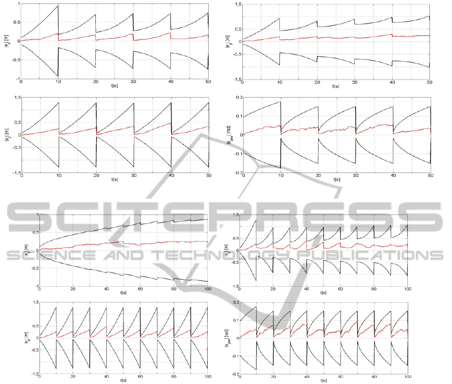
Figure 3: Average and 3σ error for x, y, z and yaw for the periodical exteroceptive measures.
Figure 4: Average and 3σ error for x, y, z and yaw for the sinusoidal trajectory test case.
while the 3σ error is of about 1%. The same
quantities considering dead reckoning alone are 8%
and 30%.
As above mentioned the underwater realm is
quite a difficult one and the communications should
be kept at a minimum, hence it has been
experimented a situation in which the vessels do not
measure continuously the distance of fellow robots
but perform an exteroreceptive measure once every
100 time steps. The results are presented in Figure 3.
It is evident the saw tooth shape due to the
periodical correction of data. In this case after 50 m
the average and 3σ errors are respectively 0.46% and
1.8%, slightly larger than the continuous case, as it
could have been expected.
In Figure 4 is shown the algorithm performance
in the case of sinusoidal trajectories, i.e. with a
constant linear velocity but an angular one slowly
varying in time as a sinusoid. Also in this case the
measures are periodic as in the previous experiment
and the number of time steps is doubled and the
average and 3σ errors are 0.28% and 1%.
Figure 5 and 6 present the trial in which the
vessels are made follow a circular trajectory for
1300 m, still with periodic exteroceptive measures.
In this case the two errors are respectively 0.05%
and 0.2%. In Figure 5 only x and y are shown for
better intelligibility.
In Figure 7 it is shown the dependence of the
average position error as a function of the number of
vehicles in the swarm. It is clear that “union is
strength”: the more the vessels the better the
estimate, until an asymptote is reached.
ThreeDimensionalLocalisationinUnderwaterSwarmsthroughaKalmanApproach
219
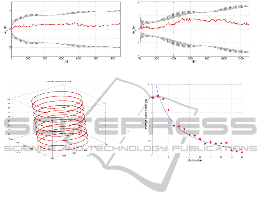
Figure 5: Average and 3σ error for x and y in the circular test case.
Figure 6: Vessels trajectories in the circular case.
5 DISCUSSION
AND CONCLUSIONS
This work has presented the results of a three
dimensional Kalman based localisation algorithm for
a swarm of underwater vehicles.
In a three dimensional environment each vessel
possesses six degrees of freedom, thus the overall
system is heavily undetermined, i.e. the covariance
on the system state quickly diverges. The
introduction of real world measures such as the yaw
angle (compass) and the z coordinate (pressure
gauge) greatly improves the Kalman filter
performance, enhancing the system observability.
It is here important to recall that the presented
scheme greatly relies on communication among the
members of the swarm. During the Kalman
computation the various vehicles must distribute to
the others their own estimates and covariance and all
the cross correlations. This heavy communication
scheme suggested the periodical exteroceptive
measures in order to reduce the number of Kalman
updates. Notwithstanding a reduced set of measures,
the system is able to assure a good localisation.
In the actual physical swarm, presently under
development, there will be two possible sonar
Figure 7: Average position error versus the swarm
numerosity.
communication channels, one around 300 Kbit/s and
a second at a higher frequency but at a smaller
range, around 1 Mbit/s. Let us now assume for the
sake of simplicity that all the transmission band can
be allocated to the Kalman 3D localisation. It is
possible to compute the total number of bytes to be
transmitted if only one robot makes a periodical
observation (one every 100 time steps as above) and
consider this as a lower bound. If all the vehicles
measure, this quantity should be multiplied by the
number of robots. These two functions are plotted in
Figure 8 where the two bounds are shown together
with the two possible transmission rates.
The diagram should be read as follows. If the
available transmission link is the lower, this
localisation system may work for a swarm smaller
than 25 members, if only one observer is allowed at
a time or with less than 13 if everybody can
measure. With the higher throughput these figures
rise to 47 and 19.
The devised algorithm strategy is based on a
mixed distributed-centralised approach. Each robot
computes the Kalman filter for all of the system
elements and it distributes its results to all the
community, since a different robot will be the next
to observe and compute the system state.
ICINCO2013-10thInternationalConferenceonInformaticsinControl,AutomationandRobotics
220
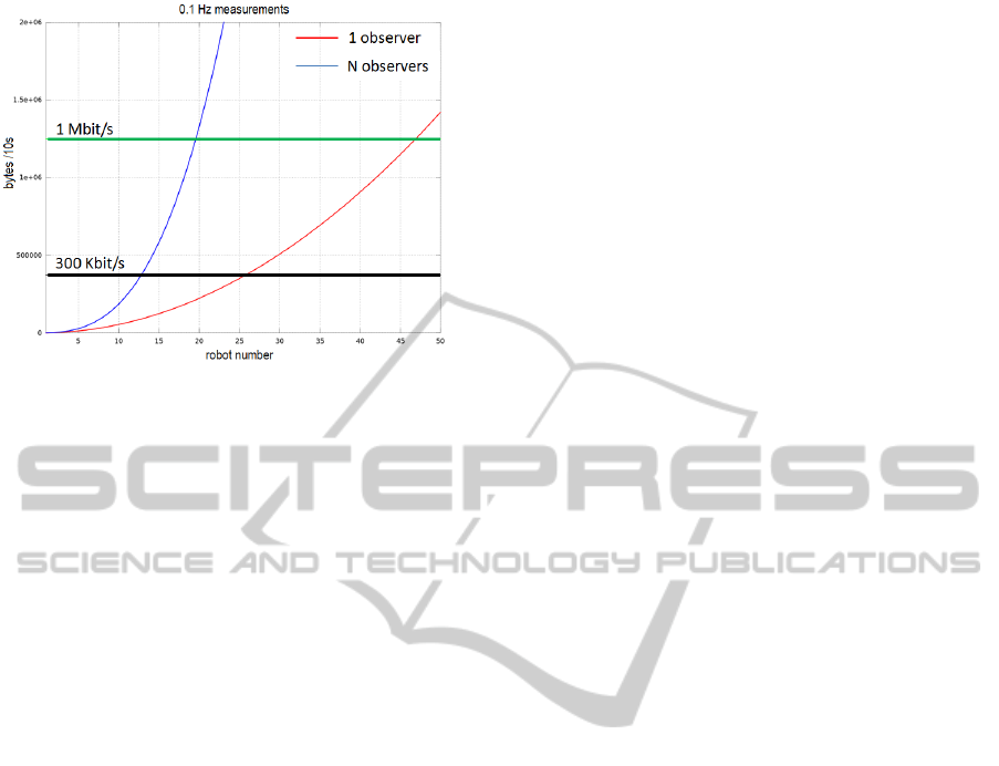
Figure 8: Needed throughput as a function of the swarm
robot number.
In conclusion it is possible to affirm that the
presented 3D Kalman based localisation system can
be employed for a swarm of underwater robots,
yielding accuracy in the computed positions, but
with a limited swarm numerosity. Nevertheless
further work is needed in order to reduce the so
precious communication bandwidth in underwater
environments and or allow more numerous swarms.
ACKNOWLEDGEMENTS
This work has been partially supported by the
HARNESS project, funded by the Italian Institute of
Technology (IIT) through the SEED initiative.
REFERENCES
Fox D., Burgard W., Kruppa H., and Thrun S., 1999.
Collaborative multirobot localization, in Proc. 23rd
Annual German Conf. Artificial Intelligence (KI),
Bonn, Germany, pp. 255–266.
Fox D., Burgard W., Kruppa H., and Thrun S., 2000. A
probabilistic approach to collaborative multi-robot
localization, Autonomous Robots, 8(3), pp. 325–344.
Huang G. P., Trawny N., Mourikis A. I., Roumeliotis S. I.,
2011. Observability-based consistent EKF estimators
for multi-robot cooperative localization, Autonomous
Robots, 30, (1), pp 99-122.
Kurazume R., Nagata S., Hirose S., 1994. Cooperative
positioning with multiple robots, in Proc. 1994 IEEE
Int. Conf. Robotics and Automation, Los Alamitos,
CA, vol. 2, pp. 1250–1257.
Kurazume R., Nagata S., Hirose S., 1996. Study on
cooperative positioning system (basic principle and
measurement experiment), in Proc. 1996 IEEE Int.
Conf. Robotics and Automation, Minneapolis, MN,
vol. 2, pp. 1421–1426.
Martinelli A., Pont F., Siegwart R., 2005. Multi-Robot
Localization Using Relative Observations, in Proc.
2005 IEEE Int. Conf. Robotics and Automation,
Barcelona, Spain, pp. 2798–2802.
Olfati-Saber R., 2007. Distributed Kalman filtering for
sensor networks, in Proc. Of the 46
th
IEEE Conf. on
Decision and Control, pp 5492-5498.
Rekleitis I. M., Dudek G., Milios E. E., 2002. Multi-robot
cooperative localization: a study of trade-offs between
efficiency and accuracy, in Proc. of International
Conference on Intelligent Robot and Systems
(IROS02), Lausanne, Switzerland, vol. 3, pp. 2690-
2695.
Roumeliotis S. I., 2000. Robust mobile robot localization:
from single-robot uncertainties to multi robot
interdependencies, Ph.D. dissertation, Elec. Eng.
Dept., Univ. Southern California, Los Angeles, CA.
Roumeliotis S. I. and Bekey G. A., 2002. Distributed
Multirobot Localization, IEEE Transaction On
Robotics And Automation, 18,(5), pp. 781-795.
Thrun S., Fox D. and Burgard W., 2000. Monte Carlo
localization with mixture proposal distribution, in
Proc. AAAI Nat. Conf. Artificial Intelligence, Austin,
TX, USA, pp. 859–865.
ThreeDimensionalLocalisationinUnderwaterSwarmsthroughaKalmanApproach
221
