
A System Design for Teleoperated Road Vehicles
Sebastian Gnatzig, Frederic Chucholowski, Tito Tang and Markus Lienkamp
Institute of Automotive Technology, Technische Universit
¨
at M
¨
unchen,
Boltzmannstr. 15, 85748 Garching b. M
¨
unchen, Germany
Keywords:
Teleoperation, Autonomous Driving.
Abstract:
The possibility to provision road vehicles unmanned and on demand will have an important influence on the
development of new mobility concepts. We therefore present the teleoperated driving of road vehicles. This
paper outlines the basic concepts, including a static multi-camera design, an operator interface with a sensor
fusion based display, and a cellular network based video transmission and communication architecture. We
also show how we manage to fulfill the system’s technical requirements with our hard- and software design and
point out the occurring problems due to communication limitations and lack of situation awareness. Finally,
we propose solutions to guarantee driving safety.
1 INTRODUCTION
We are living in a world with a rapidly growing pop-
ulation. The number of megacities with more than
ten million people will probably double in the next
decades (United Nations, 2012, pp. 5 f.). This will
have an immense effect on daily mobility. Climate
change and finiteness of fossil fuels enforce this trend.
But there is definitely no sign of a post-automobile so-
ciety (Canzler and Knie, 2009, pp. 11 f.). The future
of inner-city mobility will be integrated mobility con-
cepts, in which the automobile is one means of trans-
port among others and used in a collaborative way in
form of car-sharing (Canzler and Knie, 2009, pp. 16
ff.). This leads to an essential issue: How will the cars
be provided and distributed?
The automation of car-sharing distribution would
be the most efficient and comfortable way. The
optimal use-oriented vehicle would be driven au-
tonomously to the customer. After usage, the au-
tonomous car would park itself or drive to the next
customer. Despite the progress achieved in the re-
search of autonomous vehicles in the last thirty years,
the machine perception has not reached the human
perception skills, by far. Competitions, such as the
DARPA challenges, demonstrate the achievements of
modern robotic research (see (Thrun et al., 2006),
(Fletcher et al., 2008), (Kammel et al., 2008)). These
challenges suggest that autonomous driving in urban
environments is nonetheless possible. However, the
results of these challenges are more applicable in mil-
itary purpose. A fail-safe driving in public mixed traf-
fic is not yet feasible (Stiller, 2005, p. 5).
In contrast, teleoperation is a suitable solution to
achieve the automated distribution of automobiles.
Since the human performs quite well in the driving-
relevant skills, due to the large amount of experi-
ences and the ability to anticipate (see (Abendroth and
Bruder, 2009, pp. 13 f.), (Stiller, 2005, p. 9), (Dick-
manns, 2005, p. 204)) it is reasonable to keep him in
the loop.
2 TELEOPERATION
Teleoperated robots are commonly used for explo-
ration or surveillance tasks on ground, in the air,
and underwater. Current applications are underwa-
ter maintenance of oil platforms or reconnaissance
in conflict areas by drones, for example (see (Fong
and Thorpe, 2001)). Despite the different applications
of telerobotics, there are three characteristic elements
that are part of every teleoperated system (Winfield,
2000, pp. 148 f.):
Robot: The teleoperator is very application-
specific. Generally, it consists of at least the com-
munication hardware to receive the control signals.
Furthermore, a camera is often essential. The addi-
tional actuator and sensor equipment depends on the
application and the needed on-board autonomy (see
231
Gnatzig S., Chucholowski F., Tang T. and Lienkamp M..
A System Design for Teleoperated Road Vehicles.
DOI: 10.5220/0004475802310238
In Proceedings of the 10th International Conference on Informatics in Control, Automation and Robotics (ICINCO-2013), pages 231-238
ISBN: 978-989-8565-71-6
Copyright
c
2013 SCITEPRESS (Science and Technology Publications, Lda.)
(Winfield, 2000, p. 149)).
Communication Link: The transmission of sen-
sor and control signals is done via a communication
link. Ground and air vehicles usually need a wireless
connection. In contrast, underwater vehicles are of-
ten tethered because of the low communication band-
width of acoustic links. Besides bandwidth, latency
is the most important criterion for the choice of the
communication architecture (see (Sheridan and Ver-
plank, 1978, pp. 69 f.), (Farr et al., 2010), (Winfield,
1999)).
Operator Interface: The operator controls the
robot from an operator workstation. The interface is
usually multi modal, consisting of at least a display
visualizing live sensor data from the robot. The main
element is commonly a video image from the robot’s
perspective. Steering wheel and pedals but also joy-
sticks or touch devices are commonly used as control
inputs (see (Scribner and Gombash, 1998, pp. 4 f.),
(Fong and Thorpe, 2001), (Fong et al., 2001), (Kay
and Thorpe, 1995)).
3 DRIVING TASK
Designing a teleoperation system for remotely driv-
ing road vehicles requires the analysis of influenc-
ing variables of human driving. A human driver uses
mainly four senses. Most important are the visual
sense and the aural sense, but the haptic and vestibu-
lar system are also partially involved during driving
(J
¨
urgensohn and Timpe, 2001). The visual sense and
the aural sense are the two far senses that allow a time-
and position-related prediction. This makes these two
senses the most important for the high dynamic of the
traffic environment (Negele, 2007, p. 7).
The visual sense is not only used to perceive the own
position and environment, but also to predict and an-
ticipate the behavior of other traffic participants (see
(Abendroth and Bruder, 2009, p. 6), (Negele, 2007,
p. 10)).
Furthermore, visual stimuli have the greatest influ-
ence on velocity perception and choice of adequate
speed (see (Lank, 2010, pp. 54 ff.)). Correct veloc-
ity estimation is essential for vehicle driving. Driving
with inadequate speed is the main cause of accidents
in Germany (Statistisches Bundesamt, 2011, pp. 25
f.).
Visual information can nowadays be well perceived
by camera systems and can be realistically rendered
in modern imaging systems (Negele, 2007, p. 10).The
transformation of this sensory information to the op-
erator interface is necessary to achieve the same driv-
ing performance of an on-board driver. This process
equals the design of a driving simulator.
4 SYSTEM DESIGN
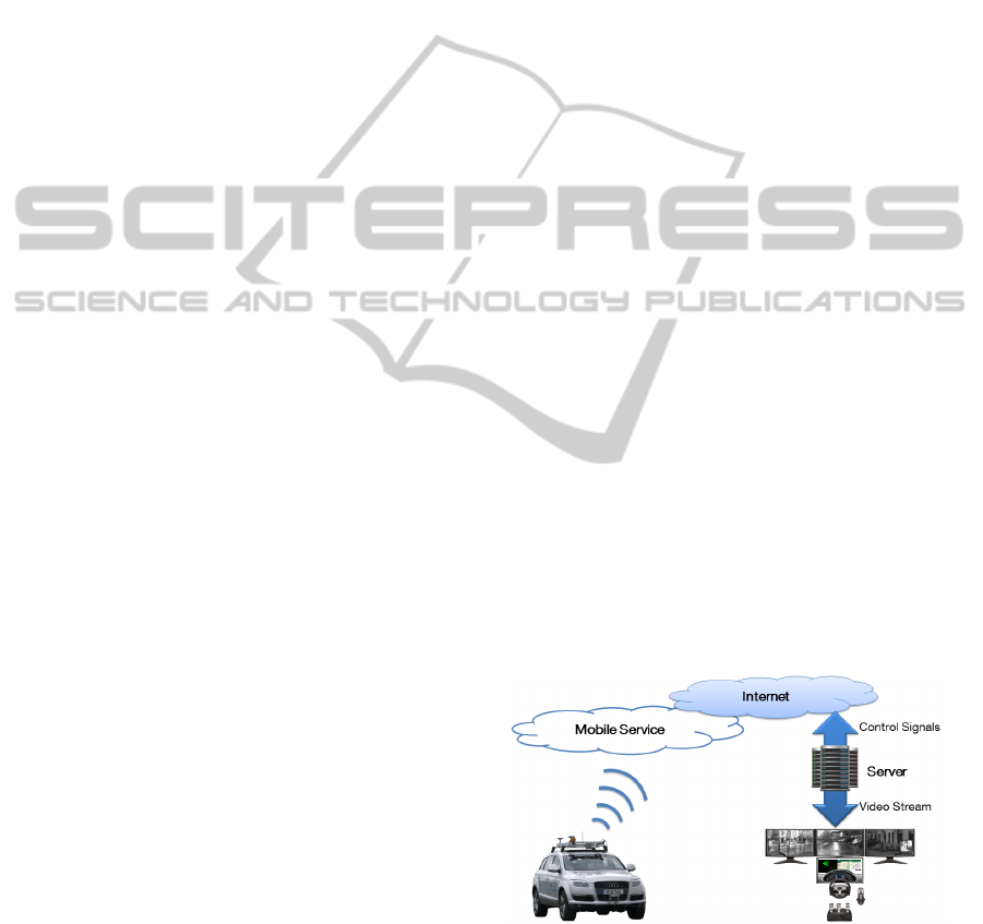
The overall concept is illustrated in Fig. 1. The opera-
tor who remotely controls the car needs to have an un-
derstanding of the car’s surroundings. As explained,
the most important sense for driving a car is the visual
one. Therefore, we need to capture the surroundings
with cameras. According to EU directives, a horizon-
tal view angle of at least 180 degrees is required in
the front to steer a vehicle. The side mirror views
should at least provide about 12 degrees each. There
should also be a rear view with about 20 degrees (The
European Parliament And The Council, 2004), (The
European Parliament And The Council, 1977).
To obtain a smooth video playback, the frame rate
is set to 25 frames per second (fps), like in the Euro-
pean PAL video standard. Transmitting the raw im-
ages in color over a cellular connection would be im-
possible due to the huge amount of data. A single
camera with 640x480 pixels, 3 bytes per pixel and 25
fps would require a bandwidth of about 184 megabits
per second (Mbps). To reduce the data rate, the video
is video-encoded.
On the operator side, the images are decoded and
displayed on a wide angle screen with a field of view
similar to the vehicle’s. The reactions of the operator
are captured using a suitable input device and trans-
mitted to the vehicle. The controllers in the vehicle
then compensate the errors between demanded and
current values.
The following sections give a detailed overview of
the concept structured by the classification introduced
in Chapter 2.
Figure 1: Data transmission scheme for teleoperated road
vehicles.
4.1 Vehicle Architecture
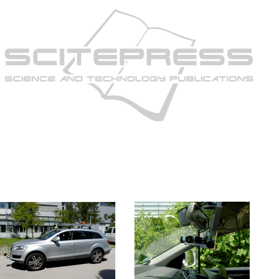
The experimental vehicle, an Audi Q7 equipped with
sensors and actuators, can be seen in Fig. 2. The sys-
tem design differentiates between the hardware and
ICINCO2013-10thInternationalConferenceonInformaticsinControl,AutomationandRobotics
232
software architecture of the experimental vehicle. The
hardware architecture describes the used sensors and
actuators that are necessary to fulfill the primary and
secondary driving task. The primary driving task con-
sists of steering, accelerating, braking and shifting.
The secondary driving task includes mostly the ma-
nipulation of the lighting system and the windscreen
wiper.
To fulfill the requirements on the field of view, the
camera system in the vehicle consists of eight cam-
eras. Each camera provides a resolution of 640x480
pixels. Fig. 3 shows the five industrial GigE cam-
eras mounted on the front of the vehicle, which cover
a field of view of approximately 240 degrees. Three
further USB cameras cover the side mirrors and the
rear view (see (Diermeyer et al., 2011)). In a sin-
gle camera setup with restricted field of view pan-
ning would be necessary to help the operator to ne-
gotiate tight corners and avoid obstacles (McGovern,
1987, p. 4). But camera panning must be fast enough
(Kay, 1997, p. 131 ). Hence, we decided to use a
static multi-camera setup which permanently covers
the complete surrounding. A software pan then dis-
plays the relevant detail of our complete surrounding.
This has the advantage that it is much faster and more
reliable than any mechanical panning system. Since
color displays have a huge effect on the perception of
objects, compared to gray scale displays (Kay, 1997),
all cameras provide color images.
A long range radar scanner and three single layer
laser scanners are used to measure the surroundings.
The radar scanner has a horizontal opening angle of
16 degrees. Each of the laser scanners has a 180
degrees field of view. This hybrid sensor network
is combined by a competitive and complementary
sensor fusion approach (see (Durrant-Whyte, 1988)).
The competitive aspects are increasing the reliability
and accuracy in front of the vehicle. The complemen-
tary fusion results in 360 degrees surround view.
In order to process the data from the different
Figure 2: Experimental vehicle equipped with sensors and
actuators.
sensors, two central processors are used. The video
streams coming from the cameras are processed and
encoded by an automotive-suitable CarPC running a
data processing framework on a windows operating
system. It also handles the complete communica-
tion between the vehicle and working station. Along-
side the CarPC, a rapid prototyping unit capable of
real-time processing undertakes the tasks of reading
the data from sensors, processing its information, and
sending appropriate control signals to the actuators
according to measured data and the driver’s inputs
coming from the working station. This rapid proto-
typing unit is basically responsible for the primary
driving task.
To achieve the steering functionality, a hollow
shaft motor has been built in the steering column di-
rectly behind the steering wheel. This motor can be
overridden anytime if a safety driver is sitting in the
vehicle.
The acceleration and braking functionality is
achieved through an electronic interface to the motor
control unit to communicate the desired motor torque
and deceleration. According to Isermann, ”For au-
tomobiles, (usually) a safe state is stand still (or low
speed) at a nonhazardous place.” (Isermann, 2006). In
order to guarantee a safe state, it is necessary to en-
sure the ability to brake at any moment. Therefore, an
additional pneumatic system is incorporated to the ve-
hicle, which makes use of a loaded air tank to directly
press on the braking pedal. A further redundancy is
implemented on a separate microcontroller. In case
of a malfunction of the rapid prototyping unit, it will
trigger a full braking emergency stop using the pneu-
matic valves.
To change the direction of driving, a shift-by-wire
system was implemented in the experimental vehicle,
which replaces the original Audi shifting mechanism.
The secondary driving tasks are also manipulated
by the rapid prototyping unit. These functions are al-
ready electronically controllable in a today’s vehicle
Figure 3: Front camera system covering a field of view of
240 degrees with five cameras.
ASystemDesignforTeleoperatedRoadVehicles
233
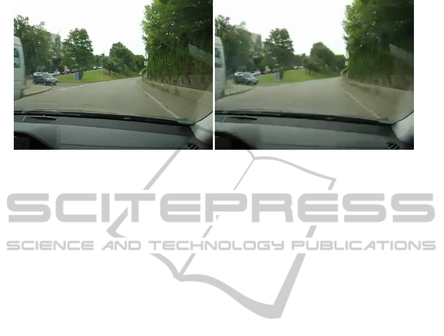
Figure 4: Comparison of video compression with high (640x480, 25.0 crf) and low (320x240, 30.0 crf) quality.
via CAN bus communication.
The software architecture consists of three lay-
ers. The network layer establishes the IP-based data
communication to the operator interface. It contains
a connection-oriented TCP connection for managing
and initializing the communication link and a connec-
tionless UDP connection for data transmission. The
connectionless data transmission leads to less over-
head and latency. In the data layer the sensor and
control data processing is performed. The validity of
the data flow and access management is verified. The
lowest level is the hardware communication layer.
Here, the different sensors and actuators are accessed
by CAN and Ethernet protocols.
4.2 Communications
The vehicle is wirelessly controlled. With respect
to the possible travelled distance of the teleoperated
vehicle, the communication infrastructure needs to
cover a wide area. To avoid a proprietary solution,
mobile Internet is a sufficient way of using an already
established infrastructure. Fortunately, the network
coverage for cellular connections is constantly grow-
ing and the available transmission speeds are increas-
ing. The current release 8 for 3G mobile networks
specifies a nominal peak downlink rate of 42 Mbps
and an uplink rate of 11 Mbps for HSPA+ (3GPP -
3rd Generation Partnership Project, 2013). In newer
releases, the data rates will be even higher. For 4G
networks, the currently specified data rates are 300
Mbps for down- and 75 Mbps for uplink. The next
evolutionary step, LTE Advanced, is expected to pro-
vide peak data rates of even 3 gigabits per second for
down- and 1.5 gigabits per second for uplink. How-
ever, as shown in (Tenorio et al., 2010), actual band-
width highly depends on signal strength and the num-
ber of users in a network cell and can be much lower
than the nominal value. The fastest currently sup-
ported 3G network standard in Germany is DC-HSPA
with a nominal downlink data rate of 42 Mbps and 10
Mbps uplink, which is provided by Telekom Deutsch-
land GmbH. With 4G, the company even offers 100
Mbps down- and 10 Mbps uplink. Since the video
transmission requires much more bandwidth than the
control input transmission, the upload bandwidth is
the limiting factor for our system. Therefore, we cur-
rently use an Internet connection over 3G and, where
available, a 4G network as communication channel.
Since 10 Mbps is the highest nominal peak uplink
data rate, one can assume that the actual data rate will
usually have about 1 to 3 Mbps. This is not suffi-
cient to transmit all video images with best quality
settings but good enough to get an overview of the
whole scene and transmit specific parts of the image
with higher quality. The three rear cameras for in-
stance are only necessary for lane changes or reverse
driving. Due to the restricted bandwidth, the video
images are encoded using the state-of-the-art H264
video codec. The compression parameters - e.g. con-
stant rate factor (crf) - and image size are continu-
ously adapted to the available bandwidth to ensure a
smooth transmission. If necessary, some cameras can
even be omitted totally. To select the best parameters,
a heuristic logic is used, which depends on the driv-
ing situation and the camera. The rule-based approach
starts reducing the quality at the outer cameras. The
driving relevant front camera gets the best quality set-
ting. Fig. 4 shows a comparison of an encoded 24
fps video with 640x480 pixels and a constant rate fac-
tor of 25 and the encoded video with 320x240 pixels
and a constant rate factor of 30. Compared to the un-
compressed video with about 177 Mbps, the bit rate
could greatly be reduced to 1678 Kbps for the high
respectively 222 Kbps for the low resolution video.
According to (Krenik, 2008), the transmission
time with a mobile 3G HSPA connection is about 50
milliseconds in each direction. For 4G networks, the
ICINCO2013-10thInternationalConferenceonInformaticsinControl,AutomationandRobotics
234
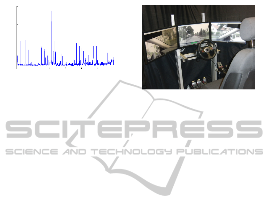
0 10 20 30 40 50 60
0
200
400
600
800
1000
1200
1400
Time [s]
Transmission delay [ms]
Average delay: 120.8192 ms
Minimum delay: 65 ms
Maximum delay: 1299 ms
Figure 5: Measured transmission delays during test drives
using a 3G network.
time delays could be reduced to 5 milliseconds in each
direction for small packets (Krenik, 2008). Fig. 5
shows an example of the round trip time (RTT) for
video and control data in a 3G cellular network that
we measured. The RTT states the time that it takes
to transmit a video image to the operator and trans-
mit a control packet back to the vehicle. This does
not include processing times on the CarPC or the op-
erator PC. While the minimum time delay resulting
from the round trip time is about 65 milliseconds, it
sometimes takes longer to transmit the packets. Even
peaks of over 1 second are possible. In this case, the
average time delay for the transmission was about 121
milliseconds. The measurement complies with the
measurements in (Prokkola et al., 2009), where the
average RTT in a 3G HSPA+ connection was about
72 milliseconds. To keep the time delay of the video
transmission as low as possible we use the connec-
tionless UDP-based RTP protocol.
4.3 Operator Interface
The working station with which the operator drives
the vehicle is shown in Fig. 6. It can be compared to
a static driving simulator.
To realize a high feeling of presence, the work-
station is assembled as a vehicle cockpit. The work-
station is equipped with conventional driver inputs as
a consumer force-feedback wheel, pedals and gear
shift. The operator sits on a usual driver seat. To
achieve an adequate field of view, three 24” monitors
are arranged next to each other. The place is sufficient
to show all five front cameras in parallel. The side and
rear mirror cameras are overlaid in the corners when
necessary.
The operator interface again consists of three lay-
ers. The network layer is the counterpart to the net-
work layer of the vehicle. Here, the operator sends the
request to take over control via the TCP-based com-
munication. The data layer mainly consists of decod-
Figure 6: Operator workstation with three monitors, control
inputs, and driver seat.
ing and displaying the images and requesting the con-
trol inputs. As described above, the quality and the
number of the displayed cameras are adapted to the
actual communication bandwidth. Furthermore, the
operator can choose different camera setups. Addi-
tionally, the operator interface shows extra informa-
tion regarding the driving task as vehicle speed or
turning signals. In order to enhance the information
available to the operator, we use a sensor fusion dis-
play (see (Fong et al., 2001)). Especially, depth per-
ception which is important for orientation and veloc-
ity perception (see (Goldstein et al., 2008, pp. 185
ff.)) is difficult in a tele-environment. To improve
the distance estimation of the operator, we use the
environmental sensor perception of the vehicle. The
data of the lidar scanners are combined in a grid based
approach. The occupancy grid gives a top view per-
spective of the obstacles in the surrounding to the op-
erator. This map is especially relevant during slow
parking maneuvers and can be displayed on an ad-
ditional monitor. During driving, the fusioned lidar
and radar scanner data is perspectively overlaid in the
video image to highlight obstacles. According to lit-
erature, operators of teleoperated vehicles often lose
their orientation (see (Kay, 1997, pp. 10 f.)). Thus,
we use a navigation map that can be shown on the
separate monitor. The hardware layer is the lowest
level of the software architecture and provides access
to the control devices.
5 RESULTS
We did several teleoperated test runs on our test track.
The test track is 650 meters long and consists of a
single lane road with 4.5 meters width. There are no
explicit road markings. The shape of the track is an
s-curve with minimal radius of 200 meters (Fig. 7).
ASystemDesignforTeleoperatedRoadVehicles
235
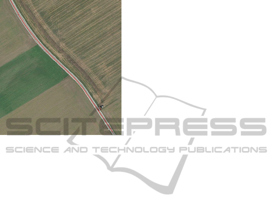
Figure 7: Birds view on section of the test track. White
lines are the tracked road boarders by the top lidar scanner,
the red line is the driven path (satellite image by Google
Earth).
During experiments the operator saw the videos with
an artificial constant time delay of 500 ms. The total
round trip time was about 550-600 ms. The average
speed during the experiments was about 30 km/h. The
speed was controlled by cruise control and the oper-
ator kept the settings constant for most of the time.
Under these conditions the operator was able to safely
keep the vehicle on the track and he was even able to
react on dynamic objects as pedestrians. The stan-
dard deviation of the lateral offset was about 0.4 me-
ter. This shows that the operator was able to follow
the lane with only little error in lane keeping. The
lateral offset was measured by the top laser scanner
that tracks the road borders. Under the described con-
ditions, the operator tends to steer the vehicle with
periodic inputs of 0.25 Hz. This still leads to a stable
behavior, but could become critical, if the speed was
increased and thus the phase margin reduced.
6 DISCUSSION
A variable time delay greatly influences the driving
performance. It was determined that a smooth im-
age sequence is rather helpful for the operator. The
artificial time delay of 500 ms showed to be unprob-
lematic for a driving speed of 30 km/h. However, test
drives have shown a reasonable speed compared to
other teleoperated road vehicles, such as (Appelqvist
et al., 2010). Due to time delays, highly dynamical
maneuvers are not possible. Speeds up to 50 km/h
should be possible with our experimental platform un-
der stable time delay conditions, 35 km/h had been
reached in the preceding tests.
Using current cellular networks, a maximum of
three cameras could be simultaneously transmitted
because of bandwidth limitations. This is not a limi-
tation, since experience showed that not more than an
horizontal field of view of approximately 135 degrees
is needed for normal straight drive. This corresponds
to three cameras transmitted simultaneously. Us-
ing gray-scale images instead of color images would
slightly reduce the required data rate but would make
it difficult to drive e.g. through shadows.
7 OUTLOOK
During our test drives, we identified several problems
that need to be solved for safe remotely controlled
driving. In (Lutz et al., 2012), we give an overview of
the legal requirements that must be met and show pos-
sible solutions. We also experienced that even with
25 images per second it is difficult to estimate the
vehicle’s speed just by relying on the video stream.
To guarantee a safe drive, two important aspects are
being investigated. First of all, the lack of situation
awareness produces an effect of nonrealistic driving
feeling, which causes the operator to perform differ-
ently compared to sitting directly inside the vehicle.
To solve this problem, methods are being studied and
implemented, where visual, aural and haptic channels
are used.
Moreover, emergency strategies during connec-
tion loss need to be developed. The implemented
approach is the so-called free corridor (Diermeyer
et al., 2011), in which the trajectory of a full brak-
ing is shown to the operator and he is responsible for
keeping it free from obstacles all the time.
One of the biggest challenges for the teleopera-
tion are time delays caused by the sensors and signal
processing as well as the transmission. While it is
possible to slightly decrease sensing and processing
times, there will still be a certain time delay in the data
transmission which depends on the wireless transmis-
sion technology and the constitution of the Internet
connection. Since this is beyond our reach, we elabo-
rated two strategies to reduce the delay effects on the
vehicle control which will further be elaborated in the
future. By predicting the vehicle’s position and the
positions of outside traffic participants, we can mod-
ify the captured video images and give the operator
a preview of the traffic scene (Chucholowski et al.,
ICINCO2013-10thInternationalConferenceonInformaticsinControl,AutomationandRobotics
236

2013). A different approach is to replace the direct
control of the vehicle by an indirect control strategy.
Instead of directly passing steering wheel, accelera-
tion and brake pedal inputs, we use a shared control
approach and generate high-level goals which are au-
tomatically achieved by the vehicle as described in
(Gnatzig et al., 2012b) and (Gnatzig et al., 2012a).
8 CONCLUSIONS
In this paper we presented the requirements to achieve
unmanned vehicles through teleoperation, showed our
solutions to meet those and outlined the problems that
we faced so far. With the presented system we could
successfully realize a teleoperated road vehicle sce-
nario. In the near future, teleoperation could be a
solution for upcoming demands resulting from new
mobility concepts.
REFERENCES
3GPP - 3rd Generation Partnership Project (2013). 3GPP
- HSPA. http://www.3gpp.org/HSPA. [Online; ac-
cessed 18-April-2013].
Abendroth, B. and Bruder, R. (2009). Die
Leistungsf
¨
ahigkeit des Menschen f
¨
ur die
Fahrzeugf
¨
uhrung. In Winner, H., Hakuli, S., and
Wolf, G., editors, Handbuch Fahrerassistenzsysteme,
pages 4–14. Vieweg + Teubner, Wiesbaden.
Appelqvist, P., Knuuttila, J., and Ahtiaine, J. (2010).
Mechatronics Design of an Unmanned Ground Vehi-
cle for Military Applications. In Di Paola, A. M. D.
and Cicirelli, G., editors, Mechatronic Systems Appli-
cations, pages 237–262. InTech.
Canzler, W. and Knie, A. (2009). Gr
¨
une Wege aus der Au-
tokrise: Vom Autobauer zum Mobilit
¨
atsdienstleister ;
ein Strategiepapier. Heinrich-B
¨
oll-Stiftung, Berlin.
Chucholowski, F., B
¨
uchner, S., Reicheneder, J., and
Lienkamp, M. (2013). Prediction Methods for Teleop-
erated Road Vehicles. In Conference on Future Auto-
motive Technology - Focus Electromobility, Garching.
Bayern Innovativ GmbH.
Dickmanns, E. D. (2005). Vision: Von Assistenz zum
Autonomen Fahren. In Maurer, M. and Stiller,
C., editors, Fahrerassistenzsysteme mit maschineller
Wahrnehmung, pages 203–237. Springer, Berlin.
Diermeyer, F., Gnatzig, S., Chucholowski, F., Tang, T.,
and Lienkamp, M. (2011). Der Mensch als Sensor -
Der Weg zum teleoperierten Fahren. In AAET - Au-
tomatisierungssysteme, Assistenzsysteme und einge-
bettete Systeme f
¨
ur Transportmittel, Braunschweig.
ITS Niedersachsen.
Durrant-Whyte, H. F. (1988). Sensor Models and Multisen-
sor Integration. The International Journal of Robotics
Research, 7(6):97–113.
Farr, N., Bowen, A., Ware, J., Pontbriand, C., and Tivey,
M. (2010). An integrated, underwater optical /acous-
tic communications system. In Proceedings of the
OCEANS 2010 IEEE SYDNEY Conference & Exhibi-
tion.
Fletcher, L., Teller, S., Olson, E., Moore, D., Kuwata, Y.,
How, J., Leonard, J., Miller, I., Campbell, M., Hutten-
locher, D., Nathan, A., and Kline, F.-R. (2008). The
MIT-Cornell collision and why it happened. Journal
of Field Robotics, 25(10):775–807.
Fong, T. and Thorpe, C. (2001). Vehicle Teleoperation In-
terfaces. Autonomous Robots, 11(1):9–18.
Fong, T., Thorpe, C., and Baur, C. (2001). Advanced Inter-
faces for Vehicle Teleoperation: Collaborative Con-
trol, Sensor Fusion Displays, and Remote Driving
Tools. Autonomous Robots, 11(1):77–85.
Gnatzig, S., Haas, E., and Lienkamp, M. (2012a).
Die Teleoperation als Ansatz zur fahrerlosen
Fahrzeugf
¨
uhrung. In 5. Tagung Fahrerassistenz.
Gnatzig, S., Schuller, F., and Lienkamp, M. (2012b).
Human-Machine Interaction as Key Technology for
Driverless Driving - A Trajectory-Based Shared Au-
tonomy Control Approach. In 21st IEEE International
Symposium on Robot and Human Interactive Commu-
nication.
Goldstein, E. B., Irtel, H., and Plata, G. (2008).
Wahrnehmungspsychologie: Der Grundkurs. Spek-
trum, Akad. Verl., Berlin [u.a.], 7 edition.
Isermann, R. (2006). Fault-diagnosis systems: An introduc-
tion from fault detection to fault tolerance. Springer,
Berlin and New York.
J
¨
urgensohn, T. and Timpe, K.-P. (2001). Kraft-
fahrzeugf
¨
uhrung. Springer, Berlin [u.a.].
Kammel, S., Ziegler, J., Pitzer, B., Werling, M., Gindele, T.,
Jagzent, D., Schr
¨
oder, J., Thuy, M., Goebl, M., Hun-
delshausen, F. v., Pink, O., Frese, C., and Stiller, C.
(2008). Team AnnieWAY’s autonomous system for
the 2007 DARPA Urban Challenge. Journal of Field
Robotics, 25(9):615–639.
Kay, J. (1997). STRIPE: Remote Driving Using Limited
Image Data. Ph.D. dissertation, Carnegie Mellon Uni-
versity, Pittsburgh.
Kay, J. and Thorpe, C. (1995). Operator Interface Design Is-
sues In A Low-Bandwidth And High-Latency Vehicle
Teleoperation System. In International Conference on
Environmental Systems.
Krenik, B. (2008). 4G wireless technology: When will
it happen? What does it offer? In 2008 IEEE
Asian Solid-State Circuits Conference, pages 141–
144. IEEE.
Lank, C. (2010). Einfluss von Fahrzeuginnenraumakustik
und vibrationen auf die Geschwindigkeitswahl
von Kraftfahrern. Ph.D. dissertation, Rheinisch-
Westf
¨
alischen Technischen Hochschule Aachen.
Lutz, L., Tang, T., and Lienkamp, M. (2012). Analyse
der rechtlichen Situation von teleoperierten und au-
tonomen Fahrzeugen. In 5. Tagung Fahrerassistenz.
McGovern, D. (1987). Experiences in teleoperation of land
vehicles. Technical Report N90-22918, Sandia Na-
tional Labs., Albuquerque NM (USA).
ASystemDesignforTeleoperatedRoadVehicles
237

Negele, H. J. (2007). Anwendungsgerechte Konzipierung
von Fahrsimulatoren f
¨
ur die Fahrzeugentwicklung.
Ph.D. dissertation, Technischen Universit
¨
at M
¨
unchen.
Prokkola, J., Perala, P. H. J., Hanski, M., and Piri, E. (2009).
3G/HSPA Performance in Live Networks from the
End User Perspective. In 2009 IEEE International
Conference on Communications, pages 1–6. IEEE.
Scribner, D. R. and Gombash, J. W. (1998). The Effect
of Stereoscopic and Wide Field of View Conditions
on Teleoperator Performance. Technical Report ARL-
TR-1598, Army Research Laboratory.
Sheridan, T. B. and Verplank, W. L. (1978). Human and
computer control of undersea teleoperators. Techni-
cal Report N00014-77-C-0256, Massachusetts Insti-
tute of Technology.
Statistisches Bundesamt (2011). Unfallentwicklung auf
deutschen Straßen 2010.
Stiller, C. (2005). Fahrerassistenzsysteme - Von realisierten
Funktionen zum vernetzt wahrnehmenden, selbstor-
ganisierenden Verkehr. In Maurer, M. and Stiller,
C., editors, Fahrerassistenzsysteme mit maschineller
Wahrnehmung, pages 1–20. Springer, Berlin.
Tenorio, S., Exadaktylos, K., McWilliams, B., and Le
Pezennec, Y. (2010). Mobile broadband field network
performance with HSPA+. In 2010 European Wireless
Conference (EW), pages 269–273. IEEE.
The European Parliament And The Council (1977).
77/649/EWG.
The European Parliament And The Council (2004).
2003/97/EG.
Thrun, S., Montemerlo, M., Dahlkamp, H., Stavens, D.,
Aron, A., Diebel, J., Fong, P., Gale, J., Halpenny,
M., Hoffmann, G., Lau, K., Oakley, C., Palatucci,
M., Pratt, V., Stang, P., Strohband, S., Dupont, C.,
Jendrossek, L.-E., Koelen, C., Markey, C., Rummel,
C., van Niekerk, J., Jensen, E., Alessandrini, P., Brad-
ski, G., Davies, B., Ettinger, S., Kaehler, A., Nefian,
A., and Mahoney, P. (2006). Stanley: The robot that
won the DARPA Grand Challenge. Journal of Field
Robotics, 23(9):661–692.
United Nations (2012). World Urbanization Prospects: The
2011 Revision. Technical Report ESA/P/WP/224.
Winfield, A. F. T. (1999). Wireless Video Tele-operation
using Internet Protocols. In Proceedings of the 14th
International Conference on Unmanned Air Vehicle
Systems.
Winfield, A. F. T. (2000). Future Directions in Tele-
operated Robotics. In Schilling, T., editor, Telerobotic
applications, pages 147–163. Professional Engineer-
ing Pub., London.
ICINCO2013-10thInternationalConferenceonInformaticsinControl,AutomationandRobotics
238
