
Identification of Orientation Dynamics of Miniature Helicopter
in Hover Mode
Damian Vigouroux, Fares Beainy and Sesh Commuri
School of Electrical and Computer Engineering, The University of Oklahoma,
110 W. Boyd St., Devon Energy Hall 150, Norman, Oklahoma 73019-1102, U.S.A.
Keywords: Miniature Helicopter, Identification, Orientation Dynamics, State Space Model, Recurrent Neural Networks,
IMU, AHRS.
Abstract: Reliable operation of helicopters in hover mode is essential for carrying out missions of surveillance,
reconnaissance, and deployment of communication networks in disaster hit areas, among many others.
Achieving autonomous operation in hover mode requires the development of robust model-based
controllers. In this paper, the use of linear and nonlinear models to identify the orientation dynamics of a
small scale helicopter is addressed. A linear architecture that combines the input-output dynamics and
perturbation-output dynamics is introduced in this paper. In contrast to the linear models that have been
reported in the literature, no assumptions about decoupled roll-pitch-yaw axes are made in the proposed
approach. The nonlinear model of orientation dynamics is identified using artificial recurrent neural
networks. Verification of these models is performed using actual data collected during the flight of the
helicopter. The results show that incorporating the perturbation dynamics in the model can result in a
description that can accurately predict the dynamics during actual flight conditions.
1 INTRODUCTION
Surveillance and reconnaissance missions typically
require operation in hard to reach and possibly
hostile areas. Additionally, most of these missions
require extended hours of continuous operation since
the zones of interest are typically remote. Therefore,
a good way to reduce the exposure of human
operators to such dangers and to relieve them from
the exhaustive long operating hours is through the
use of autonomous unmanned aerial vehicles
(UAV). Small scale helicopters stand out among the
existing UAV platforms because of their unique
capability to hover, to vertically take-off/land, and to
follow complex flight trajectories.
Despite the interest that autonomous helicopters
have received in recent years, further technological
challenges have to be addressed before these
systems can find large scale acceptance.
Instrumentation has to be improved to meet the
requirements of: (i) high computational power,
(ii) low energy consumption, (iii) low weight, and
(iv) low cost. In addition, robust controllers have to
be developed to safely guide helicopters throughout
their missions. Therefore, a complete knowledge of
the underlying forces and moments is crucial for
proper design of these controllers.
The capability of helicopters to operate in hover
mode is essential for applications like surveillance,
deployment of communication networks in disaster
hit areas, and aerial photography, among others.
Controlling the orientation dynamics of the
helicopter is crucial for maintaining the aircraft
operating in hover mode. Changing operational
conditions due to wind gusts, rotor speed variations
and different payloads affect the orientation
dynamics of the helicopter (Bejar et al., 2007).
Therefore, accurate models are needed to develop
robust controllers and increase the system
performance in variable operation conditions (Shin
et al., 2005); (Beainy et al., 2009). Theoretical
models have been proposed and the dynamical
equations representing these models have been
derived using helicopter parameters such as
moments of inertia and blade flapping angle
(Gessow and Myers, 1985); (Padfield, 2007);
(Budiyono, 2007). However, differences in fuselage
dimensions, weight etc., limit the applicability of
these models to the different micro-helicopters that
are commercially available.
In this paper, an alternative approach to
251
Vigouroux D., Beainy F. and Commuri S..
Identification of Orientation Dynamics of Miniature Helicopter in Hover Mode.
DOI: 10.5220/0004477102510258
In Proceedings of the 10th International Conference on Informatics in Control, Automation and Robotics (ICINCO-2013), pages 251-258
ISBN: 978-989-8565-71-6
Copyright
c
2013 SCITEPRESS (Science and Technology Publications, Lda.)

obtaining mathematical models of small scale
helicopter through practical identification methods is
followed (Morris et al., 1994); (Remple, 2007);
(Putro et al., 2009); (Taha et al., 2010); (Deboucha
and Taha, 2010); (Wang et al., 2011a). In this
method, a candidate model is proposed and the
unknown parameters are estimated by fitting the
response of the candidate model to dynamic data
collected from the system.
Collecting helicopter flight data is a challenging
task because of the inherent instability of the system.
A trend in previous research (Lidstone, 2003);
(Song, 2010) has been to affix the rotorcraft to a
safety structure in an attempt to lower the risks of
experimentation. The main disadvantage of this
approach is that the safety structures unavoidably
affect the dynamics of the system deteriorating the
model fidelity under real operation conditions.
The experimental approach presented in this
paper follows a different path where the system data
is collected in free flight operation (Mettler et al.,
1999); (Abbeel et al., 2010). In our study, an
experienced pilot generates control signals that
excite the helicopter orientation dynamics and keep
the system in hover mode.
Strong assumptions about the system behaviour
were used in the development of linear models used
in previous research. In (Wang et al., 2011b) the
orientation dynamics in different axes (i.e. roll,
pitch, yaw) were assumed to be decoupled and
individual Single-Input Single-Output (SISO)
models were identified for each axis. In (Morris et
al., 1994) a state space structure that assumed
coupling between the rate of change of the angular
dynamics was proposed. As a result, these models
do not accurately describe cross coupled dynamics
observed in the data.
Unlike previous works, we propose a linear
model without assumptions about de-coupled
orientation axes. Using black-box identification
techniques, a 6
th
order state space model is identified
in this paper. The proposed model is used to
estimate the orientation dynamics including the
relationships between the axes. The results obtained
show that the model is able to predict cross-axes
dynamics that previous models could not predict.
Previous works have also focused on
identification of large Radio Controlled (RC)
helicopters (i.e rotor diameters > 1200 mm). Large
RC helicopters are not as agile as the miniature (i.e.
rotor diameter < 1200 mm) version due to their large
inertia. However, miniature helicopters have less
payload capabilities compared to large RC
helicopters. This represents a further challenge
during their instrumentation. In this research, a low-
weight, low-cost acquisition system specifically
targeted for identification and control of miniature
RC helicopters is developed.
Previous works have identified models assuming
that no perturbations were present during the data
acquisition experiments. This assumption is valid
when the effects of the forces applied by the
actuators are more significant than the effects of the
external forces. Unfortunately, this is not the case
with miniature RC helicopters that have smaller
inertia and less actuator power compared to large
RC helicopters. Therefore, ignoring the effects of
perturbations during the identification of miniature
RC helicopters would significantly deteriorate the
performance of the models. In the proposed
approach the perturbations are considered during the
identification process. Separate input-output and
perturbation-output dynamic models are identified.
The proposed structure prevents the model from
over-fitting the data that improves model fidelity in
variable operation scenarios.
Nonlinear models have also been employed to
describe helicopter orientation dynamics. In
particular, artificial neural networks (ANNs) have
been extensively used because of their ability to
describe complex relationships (Suresh et al., 2002,
Putro et al., 2009, Taha et al., 2010). In this research,
an artificial neural network with autoregressive
components is investigated. Unlike the state space
model, also identified in this paper, the neural
network model does not decouple the input-output
dynamics from the perturbation-output dynamics.
The accuracy of the identified models is studied
by comparing the output of the model with actual
system outputs. The models are evaluated with the
data set used for training (i.e. identification) and also
with an independent data set. The difference in the
observed performance with the identification and the
validation data sets is used as an indicator of the
effectiveness of the model. The results obtained
show that including perturbation dynamics prevents
the model from erroneously interpreting the effects
of perturbations as if they were caused by the inputs
of the system.
The rest of this paper is organized as follows:
Section 2 presents a description of the system.
Section 3 introduces the structure of the proposed
models. The collection of flight data is explained in
Section 4 and the identification of the parameters in
the model is discussed in Section 5. Finally in
Section 6, the performance of the models is analysed
and the conclusions of the study are presented in
Section 7.
ICINCO2013-10thInternationalConferenceonInformaticsinControl,AutomationandRobotics
252
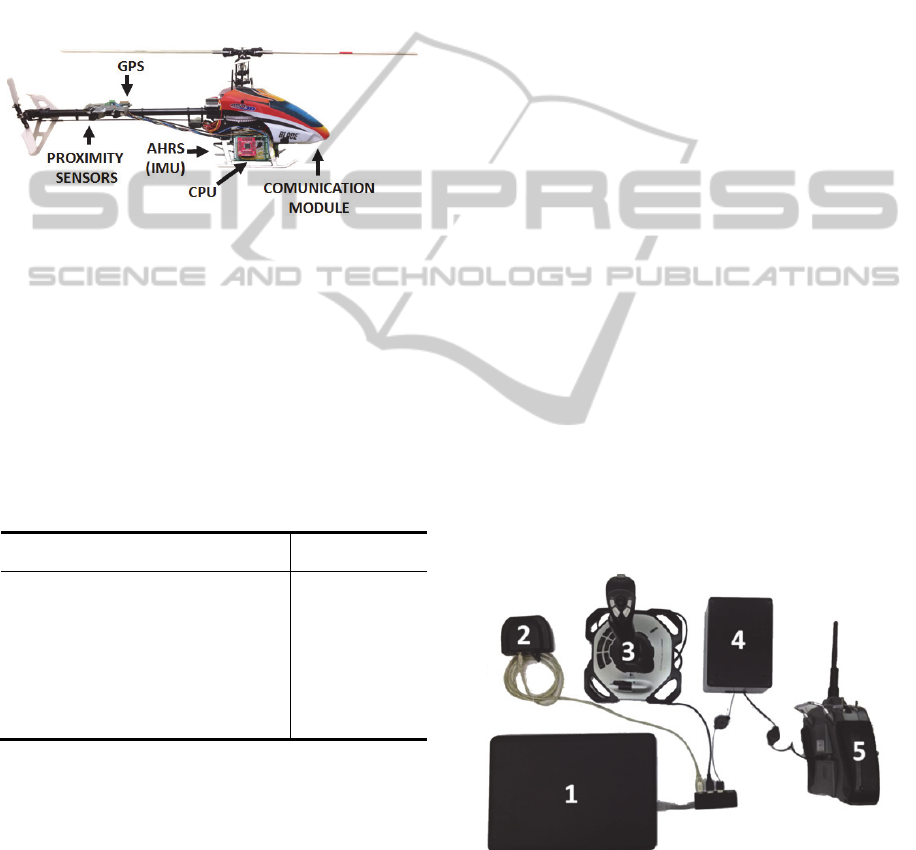
2 SYSTEM DESCRIPTION
Data collection is conducted using a fully
instrumented Blade 450-3D miniature RC helicopter
(Figure 1). This UAV belongs to the family of
Cyclic/Collective Pitch Mixing (CCPM) helicopters.
CCPM is an electronic control scheme of the
swashplate designed to reduce the mechanical
complexity of the systems used in full scale
helicopters without compromising the agility of the
rotorcraft.
Figure 1: Fully instrumented miniature helicopter used in
this research. The location of the sensors, CPU and
communication module is shown.
The diameter of the sweep of the rotor blades is
commonly used to categorize the size of the
helicopters. Helicopter rotor diameters commonly
reported in the literature are presented in Table 1.
Note that the Blade 450 3D used in this paper has a
rotor diameter of 721 mm which makes it smaller
than the helicopters used in related works.
Table 1: Helicopter sizes comparison.
Research
Rotor Diameter
(mm)
(Mettler et al., 1999) 3070
(Harbick et al., 2004) 1800
(Shin et al., 2005) 1790
(Harbick et al., 2004) 1524
(Abbeel et al., 2010) 1440
(Taha et al., 2010) 1340
(Raptis and Valavanis, 2009) 914
(He et al., 2011) 780
This Research 721
In the Blade 450-3D the elevation and
orientation are controlled through three servo
motors. These motors govern the collective and
cyclic pitch of the main rotor. The heading is guided
through the tail rotor pitch angle which is controlled
with an additional servo motor. The system counts
with ten minutes of fly autonomy provided by a
2200 mAh lithium-ion battery.
Lightweight instrumentation is developed to
measure the states of the helicopter. The orientation
of the helicopter is measured every 20 ms using an
Attitude Heading Reference System (AHRS) with
embedded Kalman filter. The position of the aircraft
is estimated every second using a GPS unit.
Ultrasonic and infrared proximity sensors are used to
obtain the estimated height when the aircraft is close
to the ground. The data acquisition by the onboard
sensors is coordinated by a 32-bit 15 MHz CPU.
The helicopter attitude (,) and heading
measured from the AHRS form the output of the
orientation dynamics model studied in this paper.
Additional information such as the rate of change of
the roll-pitch-yaw angles (
,,
) and the airframe
acceleration (
,
,
) are also estimated from the
3-axes accelerometer, 3-axes gyroscope, and 3 axes
magnetometer IMU measurements.
The data acquired from the onboard sensors is
transmitted wirelessly to the ground station (Figure
2). A RF receiver identical to the one used on the
helicopter is used to capture the control signals
transmitted to the helicopter by the ground station.
The throttle
, collective pitch
, lateral
pitch
, longitudinal pitch
and tail pitch
signals are reconstructed on the ground from the
duplicate receiver measurements. Particularly, (
,
,
) are the control signals used in the
orientation dynamics models studied in this paper.
Since the input and output signals are measured
with different acquisition systems and rates, a
synchronization scheme is developed to construct
the data sets used to identify the dynamics of the
helicopter. This is accomplished by using time
stamps on all the measurements and then
interpolating the data to generate input/output data
sets that are synchronized in time.
Figure 2: Ground station (1) Computer (2) RF receiver (3)
Joystick for assisted teleoperation (4) Duplicate onboard
RF-receiver acquisition system (5) Radio control for
manual operation.
IdentificationofOrientationDynamicsofMiniatureHelicopterinHoverMode
253
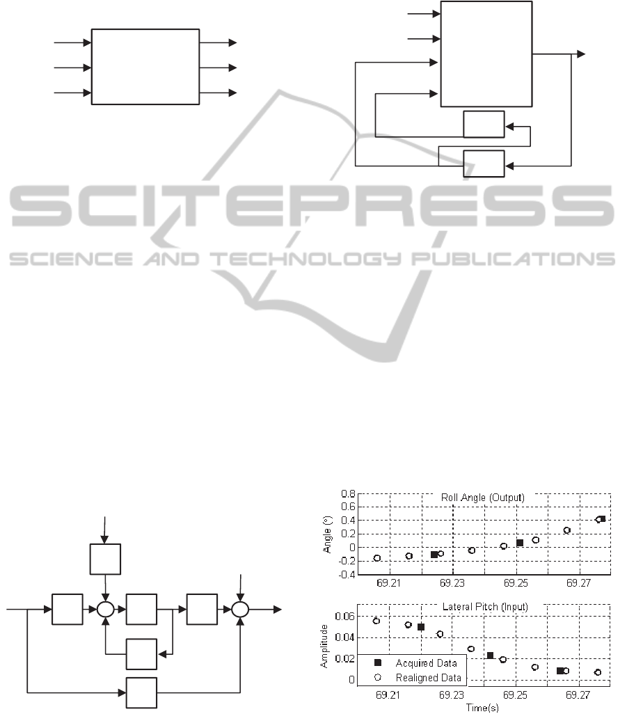
3 PROPOSED MODELS
The first step in the system identification process is
the determination of the inputs and outputs of the
desired model. The model of orientation dynamics is
shown in Figure 3.
Figure 3: Inputs and outputs of the system.
Inputs and outputs are expressed in vector form
before introducing the proposed model structures.
(1)
3.1 Linear Model
A time invariant, State Space (SS) model is used as
linear description of the system. The effects of
stochastic perturbations
are included in the
model as shown bellow
(2)
where∈
,∈
,∈
,∈
,∈
. Here,
∈
is the vector of state
variables. The perturbation
∈
and
measurement noise
∈
are vectors with
independent white Gaussian elements. The model
structure is presented graphically in Figure 4.
Figure 4: State space representation of the orientation
dynamics in discrete time. Stochastic perturbations and
measurement errors are included.
3.2 Nonlinear Model
A recurrent neural network (RNN) is the structure
used for nonlinear representation of the system. This
is shown in Figure 5.
Figure 5: RNN used as nonlinear model.
Many practical systems are successfully
described with Multilayer Perceptron (MLP) neural
networks (Demuth and Beale, 1998). For this reason
a MLP network is adopted in this research.
4 FLIGHT EXPERIMENTS
Unknown parameters of the models are determined
from input-output data collected from the system.
For this purpose the helicopter is flown in hover
mode and variations around the trim value of the
control are applied. Inputs and outputs are aligned
after the flight by interpolation using the time
stamps attached to each measurement. The
alignment process is shown in Figure 6.
Figure 6: Inputs and outputs are acquired at different times
(squares) and then uniformly interpolated (circles) as
required for identification.
ORIENTATION
DYNAMICS
MODEL
B
D
C
A
K
MIMO
RECURRENT
NEURAL
NETWORK
2 y
2
ICINCO2013-10thInternationalConferenceonInformaticsinControl,AutomationandRobotics
254

Figure 7: Data collected during test flight. The control signals of the helicopter including the inputs of the orientation
models are shown in the top. The Euler angles (i.e. outputs) are presented in the bottom part.
After the data has been aligned, inputs and
outputs can be presented at the same time instances
as shown in Figure 6. The flight test starts by
increasing the collective pitch to about 50% of its
maximum value while keeping the throttle constant
(~90%). When the collective pitch is high enough,
the rotor produces sufficient thrust and the helicopter
lifts off. The pilot applies small variations around
the trim value of the lateral, longitudinal and tail
pitch control signals to excite the dynamics of the
helicopter while keeping it operating around hover
mode.
The flight data is partitioned in two groups: one
for model identification
and other for model
validation
. The indexes and refer to the
number of points in each data set. The identification
process is described next.
5 SYSTEM IDENTIFICATION
Identification refers to the process of determining
the optimal mapping from the acquired data set
to the set of parameters Ρ
that specify the behaviour
of the model.
,
|
,…,→Ρ
(3)
In this paper, the quadratic error
,Ρ between
the model output
,Ρ
and the system response
is chosen as the performance measure to study
the accuracy of the model.
,Ρ
1
2
(4)
Ρ
argmin
,Ρ
Ρ
(5)
More information on the identification process is
presented in the next section.
5.1 Linear Model (State Space)
Identification of the State Space (SS) model consists
of first determining the order of the model and then
finding the matrices
,,,,
↔Ρ
. Using
Numerical algorithm for Subspace State Space
Identification (N4SID) (Ljung, 1988), it was first
verified that a 6
th
order model is sufficient to capture
the orientation dynamics without overfitting the
data. Figures 8 and 9 show the output of the
identified model using the training data and
validation data respectively.
5.2 Nonlinear Model (Neural Network)
In this case, the identified model parameters Ρ
are
the weights (i.e.
∈
,
∈
) of the
connections between neurons. The type of activation
function in the neurons is motivated by the positive
results reported in ( Taha et al., 2010). Hyperbolic
tangent activation function is used in the 18 neurons
of the input layer and linear activation is used in the
30 neurons of the hidden layer. In Figures 10 and 11,
the network outputs with the training data set and
with an independent data set are presented,
respectively.
70 75 80 85 90 95 100
-100
-50
0
50
100
Norm. Amplitude (%)
Control Signals (Inputs)
Throttle
Tail Pitch
Collective Pitch
Lateral Pitch
Longitudinal Pitch
70 75 80 85 90 95 100
-100
-50
0
Angle (
)
Time (s )
E
u
l
er
A
ng
l
es
(O
u
t
pu
t
s
)
Roll
Pitch
Yaw
IdentificationofOrientationDynamicsofMiniatureHelicopterinHoverMode
255
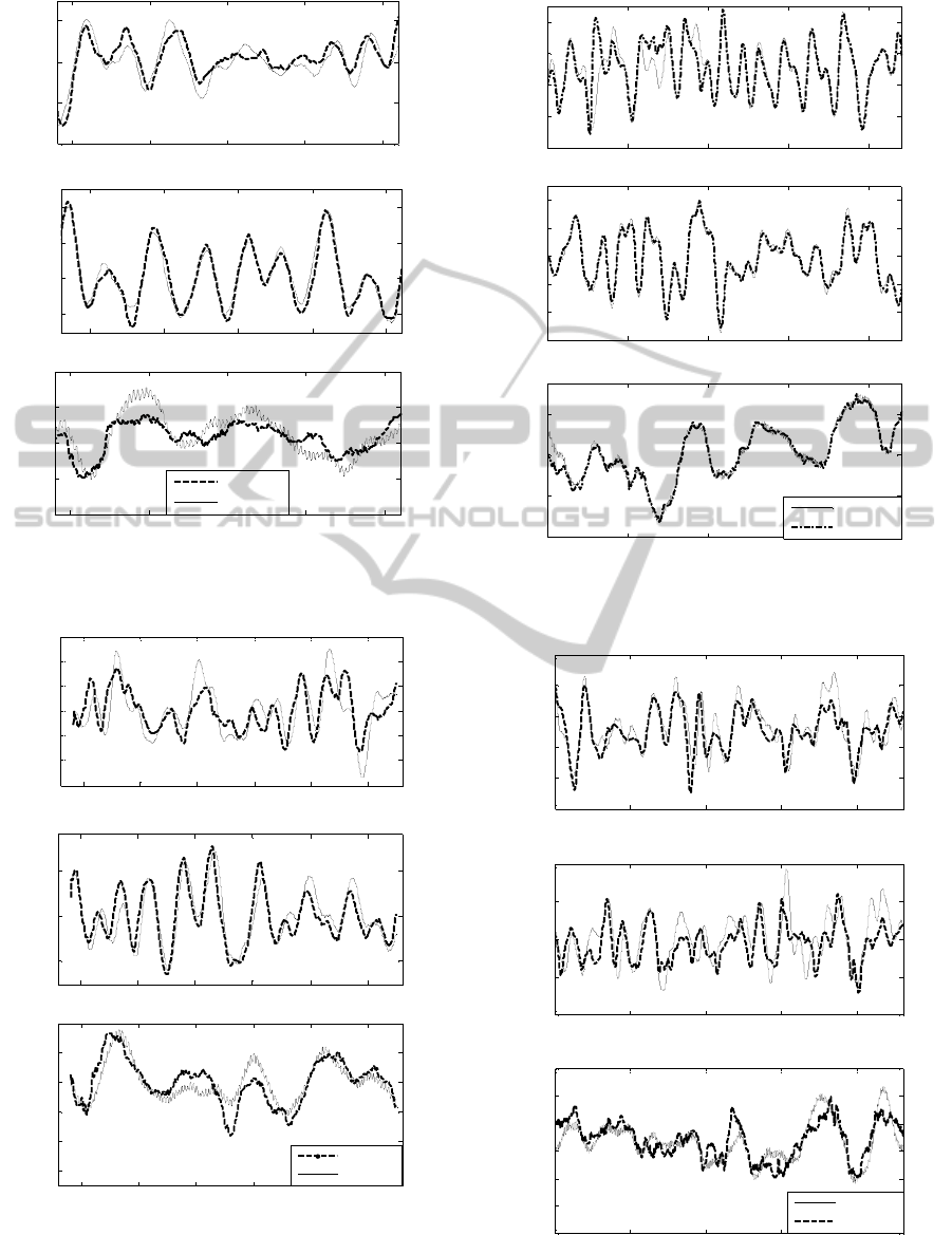
Figure 8: SS results with identification data set.
Figure 9: SS results with validation data set.
Figure 10: RNN results with training data.
Figure 11: RNN results with validation data set.
100 105 110 115 120
-20
-10
0
10
Angle (
)
Roll
100 105 110 115 120
-10
0
10
20
Angle (
)
Pitch
100 105 110 115 120
-20
-10
0
10
20
Angle (
)
Y
aw
Tim e (s )
Simulated
Measured
170 175 180 185 190 195
-15
-10
-5
0
5
10
15
Angle (
)
Roll
170 175 180 185 190 195
-10
0
10
Angle (
)
Pitch
170 175 180 185 190 195
-30
-20
-10
0
10
20
Tim e (s )
Angle (
)
Yaw
Simulated
Measured
0 5 10 15 20
-20
-10
0
10
20
Angle (
)
Roll
0 5 10 15 20
-30
-20
-10
0
10
20
Angle (
)
Pitch
0 5 10 15 20
-40
-20
0
20
Angle (
)
Yaw
Time (s )
Measured
Simulated
100 105 110 115 120
-10
-5
0
5
10
15
Angle (
)
Roll
100 105 110 115 120
-20
-10
0
10
20
Angle (
)
Pitch
100 105 110 115 120
-30
-20
-10
0
10
20
30
Angle (
)
Yaw
Tim e
(
s
)
Measured
Simulated
ICINCO2013-10thInternationalConferenceonInformaticsinControl,AutomationandRobotics
256
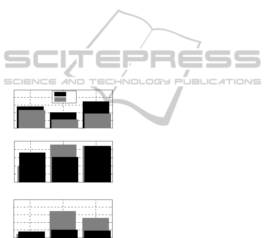
6 PERFORMANCE ANALYSIS
The Root Mean Square Error (RMSE) between the
models outputs and the measured outputs is used as
a performance indicator. In Figures 12 (a) and (b)
the RMSE of the RNN and the SS models with the
identification and validation data sets are presented,
respectively. Additionally, for each model the
difference in performance between the validation
and identification sets is presented in Figure 12-(c).
Notice that on average (i.e. taking into account the
three output channels: roll-pitch-yaw) the RNN is
0.99° more accurate than the SS model when they
are evaluated with the identification data set. On the
other hand, the RNN is on average 0.03° more
accurate than the SS when an independent data set is
used for evaluation. The average difference in the
RMSE between identification and validation sets is
1.85° for the RNN and 0.90° for the SS model.
The results show that the RNN fits better the
identification data compared to the SS.
Figure 12: (Top) RMSE between the models outputs and
the measured outputs using the identification data set;
(Middle) the RMSE with validation data set; (Bottom)
difference between RMSE with validation and
identification data sets.
However, the RNN slightly outperforms the SS with
the validation data set. The SS model shows a more
consistent performance than the RNN between
evaluations with different data sets.
7 CONCLUSIONS
The development of lightweight, low-cost
instrumentation for a miniature helicopter was
presented in this paper. Free flight experiments were
conducted during which the control signals and the
orientation in space of the helicopter were acquired.
The rotorcraft was guided by an experienced pilot to
hover while small variations around the trim value
of the control signals were applied. A key
contribution of this paper is the process for
interpolating and generating the time synchronized
data sets for identifying the mathematical model of
the orientation dynamics of the helicopter in hover
mode.
A State Space representation was used to
describe the orientation dynamics of a miniature
helicopter and the parameters of the model were
identified from the flight data. The influence of
perturbations, such as wind gusts and turbulences
was also modelled. Inclusion of perturbations in the
model is crucial because of the considerable effect
that external forces have on miniature helicopters.
Further, the model developed in this paper is also
capable of predicting cross-axes dynamics that other
models in the literature do not consider. A nonlinear
model in the form of a recurrent neural network was
also identified. The performance of both the linear
and nonlinear models was quantitatively evaluated
using the RMSE measure. The RNN described the
identification data better than the SS model but both
models had a similar performance with the
validation data set.
REFRENCES
Abbeel, P., Coates, A. & Ng, A. Y. (2010). Autonomous
Helicopter Aerobatics through Apprenticeship
Learning. International Journal of Robotics Research,
1-31.
Beainy, F., Mai, A. & Commuri, S. (2009). Unmanned
Aerial Vehicles operational requirements and fault-
tolerant robust control in level flight Control and
Automation, 2009. MED '09. 17th Mediterranean
Conference on Thessaloniki, Greece. IEEE, 700-705.
Bejar, M., Ollero, A. & Cuesta, F. (2007). Modeling and
Control of Autonomous Helicopters. Advances in
Control Theory and Applications. Berlingerlin /
Heidelberg, Germany: Springer.
Roll Pitch Yaw
0
1
2
3
4
5
RMSE [
]
(a) RMSE with Identification Data Set
SS
RNN
Roll Pitch Yaw
0
1
2
3
4
5
RMSE [
]
(b) RMSE with Validation Data Set
Roll Pitch Yaw
0
1
2
3
4
5
RMSE [
]
(c) RMSE with Validation Data Set minus
RMSE with Identification Data Set
IdentificationofOrientationDynamicsofMiniatureHelicopterinHoverMode
257

Budiyono, A. S., T.; Lesmana, H. (2007). First Principle
Approach to Modeling of Small Scale Helicopter.
International Conference on Intelligent Unmanned
Systems, Singapore. IEEE,
Deboucha, A. & Taha, Z. (2010). Identification and
Control of a Small-Scale Helicopter. Applied Physics
and Engineering (Springer), 978-985.
Demuth, H. & Beale, M. (1998). Neural Network
Toolbox: User's Guide, Version 3.0. MA, USA: The
MathWorks Inc.
Gessow, G. & Myers, A. (1985). Aerodynamics of the
Helicopter, United States of America.
Harbick, K., Montgomery, J. & Sukhatme, G. (2004).
Planar Spline Trajectory Following for an
Autonomous Helicopte. Journal of Advanced
Computational Intelligence - Computational
Intelligence in Robotics and Automation, 8, 237-242.
He, Y., Pei, H., Sun, T. & Zhou, H. (2011). Modeling,
Identification and Robust H∞ Static Output Feedback
Control of Lateral Dynamics of a Miniature Helicopter
Robotics, Automation and Mechatronics (RAM), 2011
IEEE Conference on, Qindao, China. IEEE, 310-315.
Lidstone, C. 2003. The Gimballed Helicopter Testbed.
Master of Science, University of Toronto.
Ljung, L. (1988). System Identification Toolbox For use
with MATLAB, MA, USA, The MathWorks, Inc.
Mettler, B., Tischler, M. & Kanade, T. (1999). System
Identification of Small-Size Unmanned Helicopter
Dynamics. 55th American Helicopter Society,
Montreal, Canada.
Morris, J., Nieuwstadt, M. & Bendotti, P. (1994).
Identification and Control of a Model Helicopter in
Hover. American Control Conference, Baltimore,
Maryland. 1238-1241.
Padfield, G. (2007). Helicopter Flight Dynamics, The
Theory and Application of Flying Qualities and
Simulation Modeling, Blacksburg, Virginia, United
States of America, American Institute of Aeronautics
and Astronautics, Inc.
Putro, E., Budiyono, A., Yoon, K. & Kim, D. (2009).
Modeling of Unmaned Small Scale Rotorcraft based
on Neural Network Identification. International
Conference on Robotics and Biomedics, Bangkok.
1938-1943.
Raptis, A. & Valavanis, P. (2009). System Identification
and Discrete Nonlinear Control
of Miniature Helicopters Using Backstepping. Journal of
Intelligent and Robotic Systems (Springer), 55, 223-
243.
Remple, M. T. a. R. (2007). Aircraft and Rotorcraft
System Identification, Blacksburg, Virginia, United
States of America, American Institute of Aeronautics
and Astronautics, Inc.
Shin, J., Nonami, K., Fujiwara, D. & Hazawa, K. (2005).
Model-based Optimal Attitude and Positioning
Control of Small-Scale Unmanned Helicopter.
Robotica, 23, 51-63.
Song, B. M., J.; Huang, H.; Liu, Y.; Fan, C. (2010).
Nonlinear robust control of a small-scale helicopter on
a test bench. International Journal of Control,
83,
761–775.
Suresh, S., Vijaya Kumar, M., Omkar, S. N., Mani, V. &
Smpath, P. (2002). Neural Networks Based
Identification of Helicopter Dynamics Using Flight
Data. Neural Information Processing, 2002. ICONIP
'02. Proceedings of the 9th International Conference
on, Singapore. IEEE, 10-14.
Taha, Z., Deboucha, A. & Dahari, M. (2010). Small-Scale
Helicopter System Identification Model Using
Recurrent Neural Networks. TENCON, Fukuoka.
IEEE, 1393-1397.
Wang, G., Zhu, J., Yang, C. & Xia, H. (2011a). System
Identification for Helicopter Yaw Dynamic Modelling.
International Conference on Computer Research and
Development (ICCRD), Shanghai. IEEE 54-57.
Wang, G., Zhu, J. & Zia, H. (2011b). Model Identification
and Control of a Small-Scale Unmanned Helicopter.
International Conference on Computer Science &
Education, Singapore. IEEE, 933 - 937
ICINCO2013-10thInternationalConferenceonInformaticsinControl,AutomationandRobotics
258
