
An Autonomous Mobile Inspection Robot for an Electric Power
Sub-station
Simon Thompson
1
, Satoshi Kagami
1
and Masafumi Okajima
2
1
Digital Human Research Center, National Institute of Advanced Industrial Science and Technology, Tokyo, Japan
2
Research and Development Department, Kansai Electric Power Company, Inc., Osaka, Japan
Keywords:
Autonomous Navigation, Mobile Robot, Localisation, Inspection.
Abstract:
In this work, we describe the development of an outdoor, autonomous mobile robot that performs inspections
of various facilities within an electric power sub-station. A segway-based robot was developed that can per-
form autonomous navigation along a given set of waypoints and perform inspection tasks (taking photographs
at set locations). A retractable leg system was developed to allow the robot to enter/exit self-balancing mode
and achieve a stable rest position from which to perform inspection tasks. The robot platform, localisation and
control systems, and the inspection process are described, and a real world experiment consisting of navigation
over a 1km path with 5 inspection points is reported. All inspection tasks were completed to the satisfaction
of plant operators.
1 INTRODUCTION
This paper describes the development of an outdoor
autonomous mobile robot platform that performs in-
spections of various facilities within an electric power
substation. Specifically the robot must navigate along
a given path, defined as a series of waypoints, stop-
ping at certain waypoints to take photographs of
plant facilities using a zoom-able pan/tilt camera.
The environment of the electric power substation is
large, 400x400 meters, complex, containing irregular
shaped machinery, and having areas of rough and/or
uneven terrain.
The main requirement for such a system, is an
autonomous platform capable of physically moving
through the sub-station environment while being able
to perform localisation with sufficient accuracy to
navigate through the plant and to perform the inspec-
tion task. Accurate localisation at inspection points
reduces the need for image processing to identify tar-
get locations which could prove difficult in outdoor
environments. A further requirement was the localisa-
tion system should not use GPS, as experiments with
hand-held GPS units within the sub-station proved
unreliable, perhaps due to the presence of powerful
electro-magnetic fields. To allow flexibility in assign-
ing the inspection route, it is also desirable to elimi-
nate the need for artificial landmarks.
Typical approaches to mobile robot localisation
use bayesian techniques to estimated a robot’s lo-
cation within a geometric map. Such systems usu-
ally use laser range finder range measurements and
wheel based odometry information to localise the
robot within 2D occupancy grids (Thrun et al., 2001).
The localisation process then becoming an iterative
process of predicting motion from the robot’s odom-
etry measurements and evaluating the predicted esti-
mates by matching the current sensor data with the
expected sensor data calculated from the map.
Moving from indoor robots to outdoor robots, be-
cause of the relatively unstructured nature of the envi-
ronment, the localisation problem typically changes
from 3DOF (2D position and azimuth orientation)
in 2D maps, to 6DOF (3D position and roll, pitch,
yaw) in 3D maps. This increase in the dimensions
of the state space to be estimated (and in the en-
vironment map) results in extra computational re-
quirements compared to indoor robots. With outdoor
robots typically moving faster and being larger, this
presents some problem in terms of safe and accurate
motion control based on feedback from the localisa-
tion process.
This increase in computation for outdoor localisa-
tion has led to introduction of additional localisation
cues such as GPS signals and artificial landmarks in
order to reduce the need for matching between sen-
sor data and large, complex environment maps (Thrun
et al., 2006) (Ohno et al., 2004) (Moralez and Tsub-
300
Thompson S., Kagami S. and Okajima M..
An Autonomous Mobile Inspection Robot for an Electric Power Sub-station.
DOI: 10.5220/0004480503000306
In Proceedings of the 10th International Conference on Informatics in Control, Automation and Robotics (ICINCO-2013), pages 300-306
ISBN: 978-989-8565-71-6
Copyright
c
2013 SCITEPRESS (Science and Technology Publications, Lda.)
ouchi, 2007). This can be a problem, however in
environments where GPS signals are unavailable or
unreliable, or when the installation of artificial land-
marks within the environment is unacceptable or im-
practical. In such cases, systems typically revert back
to 3DOF localisation as in (Madhavan and Durrant-
Whyte, 2004), who report a laser range finder based
3DOF localisation system for ground vehicles using
full laser scans (with 1m error) and landmarks (0.5m
error). Likewise, (Levinson et al., 2003) use the re-
flectivity of road surfaces to build image like maps
of urban environments and localise in 3DOF by cor-
recting GPS readings with map based matching of LI-
DAR range and reflectivity data, and report an impres-
sive 10cm localisation accuracy. Without GPS they
report a maximum error (measured at 50m intervals -
presumably while stopped) of 35cm. This approach,
however requires regular lane markings. A similar
system based on visual sensing of lane markings is
reported by (Xia et al., 2006) but can suffer from oc-
clusions due to a limited field of view.
As for mobile inspection robots, the majority of
reported systems are for inspections of hard to ac-
cess environments such as pipe inspection (Suzumori
et al., 1999) or for rescue activities (Osuka, 2003),
with research focused on specific mobility or sensing
environments required by such environments. (Davi-
son and Kita, 2003) report a pair of cooperating in-
door inspection robots with the application of inspect-
ing the outside of pipes in a nuclear power plant.
Stereo vision and sparse feature maps are used to ac-
curately localise the robots in small scale environ-
ments.
(Thompson et al., 2010) (Thompson et al., 2011b)
report the development of a 6DOF localisation sys-
tem that can perform accurate localisation within
dense 3D polygon maps of large outdoor environ-
ments without the use of GPS. In this work we use this
localisation system to develop a mobile robot plat-
form capable of performing an autonomous inspec-
tion task as described above.
Below, the components of the autonomous inspec-
tion robot are described, including the robot platform,
the retractable legs, the 6DOF localisation system, the
method used for motion control, and the implementa-
tion of the inspection task. Also a real world inspec-
tion task in a power sub-station consisting of 5 inspec-
tion points along a 1km path is reported. The main
contribution of the paper is the successful demonstra-
tion of an autonomous outdoor inspection task over
a wide area within an operational electric power sub-
station.
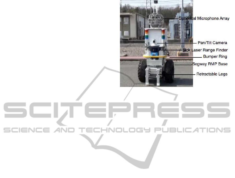
Figure 1: The inspection robot, based on a Segway RMP
base.
2 AUTONOMOUS ROBOT
SYSTEM
2.1 Robot Platform
The robot platform used is the Segway RMP 200/ATV
(Nguyen et al., 2004) which is an inverted-pendulum
type, self-balancing two-wheeled mobile robot. The
RMP was chosen as it provides a reliable base that can
operate outdoors, and has the power to traverse rough
terrain and the maneuverability to turn on the spot.
This base has been modified to mount front and back
facing Sick LMS laser range finders, and a bumper
ring. A box computer running ART Linux performs
motion control and communicates with the RMP
base, while a laptop computer (Linux, Core 2 Duo
2.26Ghz CPU, nVidia Quadro FX 770M graphics
card) runs the localisation software. ( Figure 1 shows
the robot platform. The robot also has retractable
legs which it uses for stability when not moving,
and which allows it to start/stop self-balancing mode
without human intervention. For inspection purposes
the robot is equipped with a zoom-able pan/tilt cam-
era. A 3D spherical microphone array for detecting
irregular sounds within the sub-station is also shown,
but is outside the scope of this paper (for details see
(Sasaki et al., 2012)). Stacks of different colour lights
are used to communicate the robot state to nearby hu-
mans for safety purposes.
2.2 Retractable Leg System
The Segway RMP base is a self balancing wheeled
inverted pendulum type of robot and typically must
maintain some degree of motion to stand upright.
AnAutonomousMobileInspectionRobotforanElectricPowerSub-station
301
a)
b)
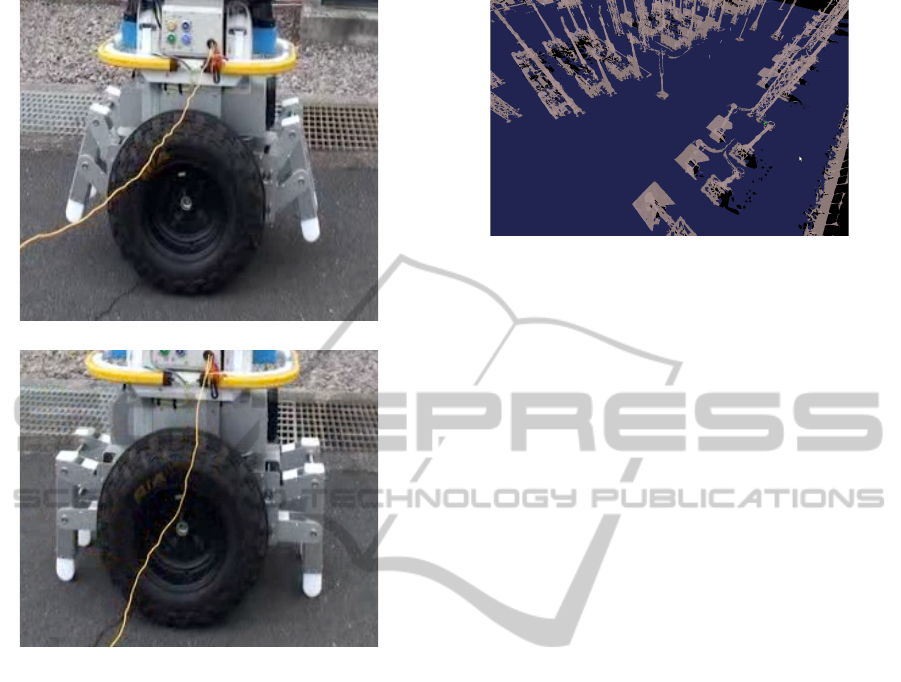
Figure 2: Active trapezoidal linked legs in a) retracted po-
sition, and b) extended position.
This complicates any inspection task requiring a sta-
ble base, such as taking a picture from a camera
mounted on the robot platform. To overcome this,
a pair of retractable legs was developed (Kabasawa
et al., 2012), to enable the robot to exit self balanc-
ing mode and assume a stable position. Figure 2
shows the legs mounted on the robot base in a) the
retracted (or ”up”) position, and b) the extended (or
”down”) position. The legs are two pairs of active
trapezoidal linked legs which also allows the robot to
stop on inclined surfaces, or with an inclined body.
From a starting position, legs down, the system initi-
ates leg retraction an immediately switches the Seg-
way control into self balancing mode. To stop, legs
are extended and when they touch the ground the self-
balancing control mode is switched off.
2.3 Dense 3D Polygon Maps
In order to localise accurately within a large, com-
plex environment such as a power sub-station, we use
dense 3D polygon maps constructed from 3D laser
Figure 3: Part of the 3D polygon map of the power sub-
station.
scans as reported in (Kagami et al., 2010). Range
data from each scan location are associated with ad-
jacent scans, and the transformation matrices were
solved. Aligned points were then converted into dense
3D polygon maps. Such realistic 3D maps allow for
knowledge of traversable terrain, as well as providing
flexibility in choice of navigation route, as most of the
structure of the environment is captured. In this study,
a map covering approximately 400 × 400m was con-
structed which contained 2, 018,418 polygons. Part
of the map is shown in Figure 3, ground surface is
shown in blue, while the grey shows various struc-
tures within the sub-station. Such complex structures,
interspersed with wide open spaces are typical of the
plant environment. This image shows approximately
120 × 80m of ground area.
2.4 6DOF Localisation
In this study a particle filter framework is adopted to
perform 6DOF localisation within the dense 3D poly-
gon maps, using odometry information from the Seg-
way RMP base, and two robot mounted laser range
finders (front and back facing). In such an approach,
a set of state estimates, or particles, are evaluated for
the likelihood that the states they represent would pro-
duce the current laser range sensor data, by comparing
it with expected range data generated using the map.
For 3DOF localisation this is relatively easy, as a 2D
map can be used. For 6DOF localisation the extra di-
mensionality of the state space, and the extension of
the map to 3D mean the computational requirements
for localisation can become unmanageable for the real
time constraints of autonomous navigation.
To perform accurate, efficient localisation in dense
polygon maps, several techniques were developed to
reduce the computational requirements involved in
matching sensor data with expected map views in the
particle filter based localisation process.:
• Constrained Motion Model: use of vehicle dy-
namics and dense 3D polygon map to limit disper-
ICINCO2013-10thInternationalConferenceonInformaticsinControl,AutomationandRobotics
302

sion of localisation belief distribution during mo-
tion (Thompson et al., 2010). Knowing the sur-
face of the current location, height pitch and roll
dispersion can be bounded.
• Indexed Polygon Map: simple grid index and
polygon classification scheme to limit number of
polygons used for to generate expected sensor
views within a given map area (Thompson et al.,
2011a)
• Selection of Polygon Sets: precompute the best
sub-set of polygons to use at each index grid based
on likely frequency of observation, angle of inci-
dence and angle of elevation of the observation
ray (Thompson et al., 2011b). This further re-
duces the number of polygons to be used for lo-
calisation within a given map area.
• GPU Based Expected View Generation: use spe-
cialised graphics hardware to reduce cost of gen-
erated expected sensor views from polygon maps.
Using these techniques, fast, accurate localisation
can be performed in large scale, dense 3D poly-
gon maps. Typical localisation results are an aver-
age of 10cm localisation error with a cycle rate of
approximately 10Hz. Experiments within the sub-
station environment have produced average localisa-
tion error of 3cm over simple paths that travel close
(within 10m) to plant machinery and thus have strong
localisation cues. For details of experimental re-
sults on localisation accuracy see (Thompson et al.,
2011a)(Thompson et al., 2011b). Localisation perfor-
mance was not significantly affected by observed en-
vironmental changes such as sparse pedestrians, oc-
casional passing vehicles, addition/removal of stored
equipment, and even the addition of demountable
buildings.
One problem with the localisation system that was
observed in development, was failure due to tempo-
rary loss of odometry information. In certain areas
of the sub-station, the robot pass through areas with
strong electro-magnetic fields which caused the USB
connection from the RMP base to the navigation con-
trol system to disconnect, resulting in loss of odom-
etry information while the robot comes to a stop. A
simple system to monitor the connection, and in the
case of disconnection to ”fake” approximate odome-
try (with appropriate uncertainty) of the stopping mo-
tion while attempting reconnection, was developed.
2.5 Path Following Control System
To perform autonomous navigation the robot system
employs a path following method known as the pure
pursuit algorithm (Heredia and Ollero, 2007). The
path is defined by a series of way points, and line seg-
ments connecting the way points form the reference
path. The pure pursuit algorithm attempts to follow
the path by computing a circular arc from the esti-
mated robot position to a point some distance along
the reference path. This ”look ahead” distance varies
depending on current velocity and whether a way-
point or goal location is near. In this work, no ob-
stacle avoidance is implemented as it is a controlled
environment and the robot should not deviate unex-
pectedly from its path. If an object is detected in its
paths, the robot simply stops and waits until the path
is clear.
3 INSPECTION TASK
The inspection task involves taking a photograph
of various facilities for later viewing by plant per-
sonel. Each inspection consists of the following sub-
behaviours:
1. navigating to a predefined point within the sub-
station
2. turning to a desired orientation if required
3. lowering legs for stability
4. camera performing pan/tilt and zoom as required
5. taking the photograph
6. raise legs
7. proceed to next way-point.
In order to give a set of inspection tasks to the robot,
a high level command language was defined:
• START x y: defines a start location by x and y
coordinates within the given map.
• GOTO x y: define a navigation way-point within
the given map
• TURN theta: turn the robot to a given global ori-
entation.
• INSPECT id x y z zoom: defines an inspection task
in terms of an identification number, a three di-
mensional location, and a camera zoom parame-
ter.
For any specific inspection task, the robot performs
the following sequence of commands (with appropri-
ate parameters): GOTO, TURN, INSPECT. First the
robot navigates to the given way-point in the GOTO
command parameters using the localisation and con-
trol systems described above. Then the robot turns
to the given orientation theta, again using the lo-
calisation estimate for feedback. The legs are then
lowered, and the robot-self-balancing mode disabled.
AnAutonomousMobileInspectionRobotforanElectricPowerSub-station
303
a) b)
c) d)
e) f)
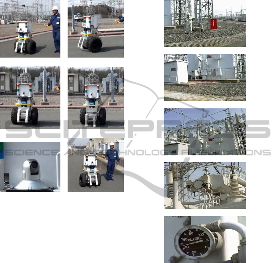
Figure 4: An example of the inspection procedure: a) robot
moves towards the inspection point, b) stops at point, c)
turns to required orientation, d) put s legs down to stabi-
lize platform, e) activates pan-tilt camera to take inspection
photograph, f) retracts legs and continues to next way-point.
Once the robot is motionless and stable, the current
6DOF localisation estimate and the 3D location given
in the x,y,z parameters to the INSPECT command
(defined in relation to global map coordinates), are
used to calculate a pan/tilt configuration which orien-
tates the camera towards the inspection point. Once
correctly orientated, the camera’s zoom control is ad-
justed according to the zoom parameter, and the pic-
ture is taken.
4 EXPERIMENTAL RESULTS
Real world experiments demonstrating autonomous
inspection were performed at an operational electric
power sub-staion operated by Kansai Electric Power
Company (Japan).
a)
b)
c)
d)
e)
Figure 5: An example of an inspection photograph taken
by robot, images show view from pan-tilt camera: a) view
when legs are lowered, b) pan to required orientation, c) tilt
to required elevation, d) zooming to target, e) photograph
taken for inspection task.
4.1 Single Inspection Task
Figure 4 shows the robot during an inspection task,
sub-figure a) robot moves towards the inspection
point, b) stops at point, c) turns to required orienta-
tion, d) put s legs down to stabilize platform, e) acti-
vates pan-tilt camera to take inspection photograph, f)
retracts legs and continues to next way-point. Figure 5
shows images from the pan-tilt camera during the in-
spection task. Sub-figure a) shows the view after the
ICINCO2013-10thInternationalConferenceonInformaticsinControl,AutomationandRobotics
304
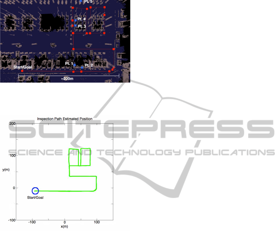
Figure 6: Inspection task within polygon map. Naviga-
tion path (red squares (waypoints) and red lines (connecting
paths), and inspection points (blue squares) labelled one to
five.
Figure 7: The estimated path traveled by the robot during
the inspection task.
robot has, stopped turned to the required orientation
and lowered it’s legs; b) after the camera has per-
formed a pan motion; c) after tilt motion; d) in the
process of zooming; e) the photo taken for the in-
spection task. In this example the inspection point
was over 15m from the robot stopping position, and a
gauge of approximately 15cm was photographed us-
ing just the robot’s estimated position for guidance.
4.2 Inspection of an Electric Power
Sub-station
The inspection task required the robot to navigate
over a 1km path throughout a power sub-station
within one hour, performing inspection tasks at five
separate places within the environment (Fig. 6). In-
spection points are things like transformers, gauges
and latches. The inspection points were manually de-
fined by operators, with the 3D coordinates of the
points being recovered from the polygon map. The
robot traveled over the path with a maximum speed
of 0.6m/s The inspection task was completed within
23 minutes, with all five inspection points captured
to the satisfaction of plant operators. The estimated
path the robot traveled is shown in Figure 7. Average
localisation error was approximately 10cm.
5 CONCLUSIONS
In this paper we have presented an autonomous mo-
bile robot capable of performing an inspection task
within the grounds of an electric power sub-station.
Fast, accurate 6DOF localisation, using onboard-
sensors only, in conjunction with a retractable leg
system which stabilizes the robot base, allowed the
mobile robot to take precise photographs of inspec-
tion targets. A high level command language was de-
scribed, and a successful, real-world inspection task
was reported.
Although in this study, the inspection task was
completed satisfactorily with just the use of the es-
timated robot position, ideally the localisation result
would provide an initial estimate for an image pro-
cessing system to perform a local search for the in-
spection target, and subsequently to give autonomous
confirmation that the task was achieved. Also in this
case, the robot did not perform any obstacle avoid-
ance. Subsequent work aims at 3D sensing and avoid-
ance of potential obstacles, although this should oc-
cur in a predictable, safe and operator approved man-
ner. Further study is also needed to evaluate long term
autonomous operation in terms of inspection success
rate and localisation performance in various weather
conditions.
REFERENCES
Davison, A. and Kita, N. (2003). Active visual localisation
for cooperating inspection robots. In IEEE/RSJ Inter-
national Conference of Intelligent Robots and Systems
(IROS).
Heredia, G. and Ollero, A. (2007). Stability of autonomous
vehicle path tracking with pure delays in the control
loop. In Advanced Robotics, Vol 21, No. 1-2.
Kabasawa, M., Thompson, S., Kagami, S., and Okajima, M.
(2012). Development of trapezoidal linked legs for a
wheeled inverted pendulum. In JSME Robotics and
Mechatronics Conference.
Kagami, S., Hanai, R., Hatao, N., and Inaba, M. (2010).
Outdoor 3d map generation based on planar feature
AnAutonomousMobileInspectionRobotforanElectricPowerSub-station
305

for autonomous vehicle navigation in urban environ-
ment. In Int. Conf. on Intelligent Robots and Systems
(IROS).
Levinson, J., Montemerlo, M., and Thrun, S. (2003). Map-
based precision vehicle localisation in urban environ-
ments. In Proceedings of Robots, Science and Sys-
tems.
Madhavan, R. and Durrant-Whyte, H. F. (2004). Terrain-
aided localization of autonomous ground vehicles. In
Automation in Construction.
Moralez, Y. and Tsubouchi, T. (2007). Gps moving perfor-
mance on open sky and forested paths. In Proc. of the
Int. Conf. on Intelligent Robots and Systems.
Nguyen, H. G., Morrell, J., Mullens, K., Burmeister, A.,
Miles, S., Farrington, N., Thomas, K., and Gage, D.
(2004). Segway robotic mobility platform. In SPIE
Proc, 5609: Mobile Robots XVII,.
Ohno, K., Tsubouchi, T., Shigematsu, B., and Yuta, S.
(2004). Proper use of gps for outdoor navigation by
an autonomous mobile robot. In Proceedings of Int.
Conf. on Intelligent Autonomous Systems.
Osuka, K. (2003). Development of mobile inspection robot
for rescue activities: Moira. In IEEE/RSJ Interna-
tional Conference of Intelligent Robots and Systems
(IROS).
Sasaki, Y., Kabasawa, M., Thompson, S., Kagami, S., and
Oro, K. (2012). Spherical microphone array for spatial
sound localisation for a mobile robot. In Proc. of the
Int. Conf. on Intelligent Robots and Systems.
Suzumori, K., Miyagawa, T., Kimura, M., and Hasegawa,
Y. (1999). Micro inspection robot for 1-in pipes. In
IEEE/ASME Transactions on Mechatronics, Vol. 4,
No. 3.
Thompson, S., Kagami, S., and M.Okajima (2011a). Facet
classification in 3d polygon maps for autonomous ve-
hicle localisation. In Proc. of the Int. Conf. on Intelli-
gent Unmanned Systems.
Thompson, S., Kagami, S., and M.Okajima (2011b). Se-
lection of polygon sets for 6dof localisation of au-
tonomous vehicles. In Proc. of the Int. Conf. on Sys-
tems, Man and Cybernetics.
Thompson, S., Kagami, S., and Okajima, M. (2010). Con-
strained 6dof localisation for autonomous vehicles. In
Proc. of the Int. Conf. on Systems, Man and Cybernet-
ics,.
Thrun, S., Burgard, W., and Fox, D. (2001). Robust monte
carlo localisation for mobile robots. In Artificial Intel-
ligence, vol. 128.
Thrun, S., Montemerlo, M., Dahlkamp, H., Stavens, D.,
Aron, A., Diebel, J., Fong, P., Gale, J., Halpenny,
M., Hoffmann, G., Lau, K., Oakley, C., Palatucci, M.,
Pratt, V., Stang, P., Strohband, S., Dupont, C., Jen-
drossek, L., Koelen, C., Markey, C., Rummel, C., van
Niekerk, J., Jensen, E., Alessandrini, P., Bradski, G.,
Davies, B., Ettinger, S., Kaehler, A., Nefian, A., , and
Mahoney, P. (2006). Stanley: The robot that won the
darpa grand challenge. In Journal of Field Robotics,
Vol. 23, No. 9, June.
Xia, T. K., Yang, M., and Yang, R. Q. (2006). Vision based
global localization for intelligent vehicles. In Pro-
ceedings of the Intelligent Vehicles Symposium.
ICINCO2013-10thInternationalConferenceonInformaticsinControl,AutomationandRobotics
306
