
A Computational Cognition and Visual Servoing based Methodology
to Design Automatic Manipulative Tasks
Hendry Ferreira Chame and Philippe Martinet
Robotics Team of the Institut de Recherche en Communications et Cybern
´
etique de Nantes (IRCCyN), Nantes, France
Keywords:
Cognitive Robotics, Computational Cognition, Artificial Intelligence, Visual Servoing.
Abstract:
In the last decades, robotics has exerted an important role in the research on diverse knowledge domains,
such as, artificial intelligence, biology, neuroscience and psychology. In particular, the study of knowledge
representation and thinking, has led to the proposal of cognitive architectures; capturing essential structures
and processes of cognition and behavior. Robotists have also attempted to design automatic systems using
these proposals. Though, certain difficulties have been reported for obtaining efficient low-level processing
while sensing or controlling the robot. The main challenges involve the treatment of the differences between
the computational paradigms employed by the cognitive and the robotic architectures. The objective of this
work, is to propose a methodology for designing robotic systems capable of decision making and learning
when executing manipulative tasks. The development of a system called the Cognitive Reaching Robot (CRR)
will be reported. CRR combines the advantages of using a psychologically-oriented cognitive architecture,
with efficient low-level behavior implementations through the visual servoing control technique.
1 INTRODUCTION
In the last decades, with the venue of fields of study
such as cybernetics, artificial intelligence, neuro-
science and psychology; remarkable progresses have
been made in the understanding of what is required
to create artificial life evolving in real-world environ-
ments (Arbib et al., 2008). Still, one of the remain-
ing challenges is to create new cognitive models that
would replicate high-level capabilities; such as, per-
ception and information processing, reasoning, plan-
ning, learning, and adaptation to new situations.
The study of knowledge representation and think-
ing has led to the proposal of Cognitive Architec-
tures. A Cognitive Architecture (CA) can be con-
ceived as a broadly-scoped, domain-generic compu-
tational cognitive model, which captures essential
structures and processes of the mind, to be used for
a broad, multiple-level, multiple-domain analysis of
cognition and behavior (Newell, 1994). For cognitive
science (i.e., in relation to understanding the human
mind) a CA provides a concrete mechaniscist frame-
work for more detailed modeling of cognitive phe-
nomena; through specifying essential structures, di-
visions of modules, relations between modules, and
so on (Duch et al., 2008).
A robot that employs a CA to select its next ac-
tion, is derived from integrated models of the cog-
nition of humans or animals. Its control system is
designed using that integrated CA and is structurally
coupled to its underlying mechanisms (Sun, 2009).
However, there are challenges associated with using
these architectures in real environments; in particular,
for performing efficient low-level processing (Han-
ford and Long, 2011). It can be hard, thus, to gener-
ate meaningful and trustful symbols from potentially
noisy sensor measurements, or to exert control over
actuators using the representation of knowledge em-
ployed by the CA.
Cognitive models are derived from a large spec-
trum of computational paradigms that are not neces-
sarily compatible when considering underlying soft-
ware architecture requirements. Scientists in cogni-
tion research, and actually higher-level robotic ap-
plications, develop their programs, models and ex-
periments using a language grounded in an ontology
based on general principles (Huelse and Hild, 2008).
Hence, they expect reasonable and scalable perfor-
mance for general domains and problem spaces.
On the side of cognitive robotists, it would not be
reasonable to replace already existing robust mecha-
nisms ensuring sensory-motor control by less efficient
ones. Such is the case of the visual servoing technique
which uses computer vision data to control the motion
213
Ferreira Chame H. and Martinet P..
A Computational Cognition and Visual Servoing based Methodology to Design Automatic Manipulative Tasks.
DOI: 10.5220/0004480802130220
In Proceedings of the 10th International Conference on Informatics in Control, Automation and Robotics (ICINCO-2013), pages 213-220
ISBN: 978-989-8565-70-9
Copyright
c
2013 SCITEPRESS (Science and Technology Publications, Lda.)

of the robot’s effector (Corke, 2011). This approach
has the advantage of allowing the control by directly
measuring the error on the effector’s interaction with
the environment; making it robust to inaccuracies in
estimates of the system parameters (Chaumette and
Hutchinson, 2006).
This research seeks to contribute to the debate
standing from the point of view of cognitive roboti-
cists. It can be conceived as an effort to assess to what
extent it is feasible to build cognitive systems mak-
ing use of the benefits of a psychologically-oriented
CA; without leaving behind efficient control strate-
gies such as visual servoing. The aim is to verify the
potential benefits of creating an interactive platform
under these technologies; and to analyze the resulting
flexibility in automating manipulative tasks.
2 COGNITIVE ARCHITECTURES
According to (Kelley, 2003), two key design prop-
erties that underlie the development of any CA are
memory and learning. Various types of memory serve
as a repository for background knowledge about the
world, the current episode, the activity, and oneself;
while learning is the main process that shapes this
knowledge. Based on these two features, different ap-
proaches can be gathered in three groups: symbolic,
non-symbolic, and hybrid models.
A symbolic CA has the ability to input, output,
store and alter symbolic entities; executing appropri-
ate actions in order to reach goals (Newell, 1994).
The majority of these architectures employ a central-
ized control over the information flow from sensory
inputs, through memory; to motor outputs. This ap-
proach stresses the working memory executive func-
tions, with an access to semantic memory; where
knowledge generally has a graph-based representa-
tion. Rule-based representations of perceptions / ac-
tions in the procedural memory, embody the logical
reasoning of human experts.
Inspired by connectionist ideas, a sub-symbolic
CA is composed by a network of processing nodes
(Duch et al., 2008). These nodes interact with each
other in specific ways changing the internal state of
the system. As a result, interesting emergent proper-
ties are revealed. There are two complementary ap-
proaches to memory organization, globalist and lo-
calist. In these architectures, the generalization of
learned responses to novel stimuli is usually good,
but learning new items may lead to problematic inter-
ference with existent knowledge (O’Reilly and Mu-
nakata, 2000).
A hybrid CA combines the relative strengths of
the first two paradigms (Kelley, 2003). In this sense,
symbolic systems are good approaches to process and
executing high-level cognitive tasks; such as, plan-
ning and deliberative reasoning, resembling human
expertise. But they are not the best approach to rep-
resent low-level information. Sub-symbolic systems
are better suited for capturing the context-specificity
and handling low-level information and uncertainties.
Yet, their main shortcoming are difficulties for repre-
senting and handling higher-order cognitive tasks.
3 VISUAL SERVOING
The task in visual servoing (VS) is to use visual fea-
tures, extracted from an image, to control the pose of
the robot’s end-effector in relation to a target. The
camera may be carried by the end-effector (a con-
figuration known by eye-in-hand) or fixed in (eye-to-
hand) (Corke, 2011). The aim of all vision-based con-
trol schemes is to minimize an error e(t), which is
typically defined by
e(t) = s(m(t), a) − s
∗
(1)
The vector m(t) is a set of image measure-
ments used to compute a vector of k visual features
s(m(t),a), based on a set of parameters a represent-
ing potential additional knowledge about the system
(i.e., the camera intrinsic parameters, or a 3-D model
of the target). The vector s
∗
contains the desired val-
ues of the features.
Depending on the characteristics of the task, a
fixed goal can be considered where changes in s de-
pend only on the camera’s motion. A more general
situation can also be modeled, where the target is
moving and the resulting image depends both on the
camera’s and the target’s motion. In any case, VS
schemes mainly differ in the way s is designed. For
image-based visual servo control (IBVS), s consists of
a set of features that are immediately available in the
image data. For position-based visual servo control
(PBVS), s consists of a set of 3D parameters, which
must be estimated from image measurements. Once s
is selected, a velocity controller relating its time vari-
ation to the camera velocity is given by
˙s = L
s
V
c
(2)
The spatial velocity of the camera is denoted by
V
c
= (v
c
,ω
c
), with v
c
the instantaneous linear velocity
of the origin of the camera frame and ω
c
the instanta-
neous angular velocity of the camera frame. L
s
∈ R
6×k
is named the interaction matrix related to s.
Using (1) and (2), the relation between the camera
velocity and the time variation of e can be defined by
ICINCO2013-10thInternationalConferenceonInformaticsinControl,AutomationandRobotics
214
˙e = L
e
V
c
(3)
Considering V
c
as the input to the controller, if an
exponential decoupled decrease of e is desired, from
(3) the velocity of the camera can be expressed by
V
c
= −λL
+
e
e (4)
where L
+
∈ R
6×k
is chosen as the Moore-Penrose
pseudoinverse of L
e
, that is L
+
e
= (L
e
t
L
e
)
−1
L
e
t
when
L
e
is of full rank 6. In case k = 6 and det(L
e
) 6= 0, it is
possible to invert L
e
giving the control V
c
= −λL
e
−1
e.
Following (4), the six components of V
c
are given
as input to the controller. For robots with less than
six degrees of freedom, the control scheme may be
expressed in the joint space by
˙q = −λ(J
e
+
e + P
e
e
s
) − J
e
+
∂e
∂t
(5)
where J
e
is the feature Jacobian matrix associated
with the primary task e, P
e
= (I
6
−
b
J
e
+
b
J
e
) is the gra-
dient projection on the null space of the primary task
to accomplish a secondary task e
s
, and
b
∂e
∂t
models the
motion of the target. An example of VS is presented
in Figure 1.
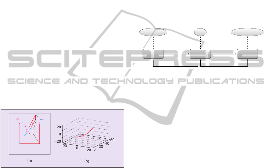
Figure 1: IBVS example. (a) Image points trajectories (c)
3-D trajectory of the camera optical center (Chaumette and
Hutchinson, 2007).
4 THE CRR PROPOSAL
The Cognitive Reaching Robot (CRR) is a system
designed to perform interactive manipulative tasks.
When compared to non-cognitive approaches, CRR
has the advantage of being adaptive to variations of
the task; since the reinforcement learning mechanism
reduces the need for explicitly reprogramming the be-
havior of the robot. Furthermore, CRR is robust to
changes in the robotic system due to wear. It is toler-
ant to calibration errors by employing visual servoing;
where modeling errors are compensated in the control
loop (the camera directly measures the task errors).
The platform presents a modular organization (as
shown in Figure 2) and is composed by three mod-
ules. The cognitive module is responsible for sym-
bolic decision making and learning. The auditory
module processes speech recognition. The visuomo-
tor module is in charge of applying the VS control. To
enable inter-modular communication, six topics were
defined. Topics are named buses over which modules
exchange messages. According to the sensory modal-
ities that compose CRR, auditory, proprioceptive and
visual topics were defined. The aim of these topics is
sending sensory information to the cognitive module.
Similarly, the cognitive module sends commands to
the auditory, visual and proprioceptive modules.
Cognitive
Module
Auditory
Module
Visuomotor
Module
Soar
Voce Library ViSP / OpenCV
AUS VIC/PRC
VIS/PRSAUC
Figure 2: The CRR architecture. The boxes represent mod-
ules and the ovals indicate the libraries wrapped inside the
modules. The links between modules indicate topics. AUS:
auditory sensory, PRS: proprioceptive sensory, VIS: visual
sensory, AUC: Auditory command, VIC: Visual command,
PRC: Proprioceptive command.
Hardware Components. The design of CRR
aimed to praise the reusability of equipments, so its
hardware components were chosen according to a cri-
teria of accessibility in the robotic lab. The project
considered a St
¨
aubli TX-40 robot manipulator, an
AVT MARLIN F-131C camera, and a DELL Vostro
1500 laptop (Intel Core 2 Duo 1.8GHz 800Mhz
FSB, 4.0GB DDR2 667MHz RAM, 256MB NVIDIA
GeForce 8600M GT).
Software Components. Three criteria grounded
the choice for software technologies: source avail-
ability, efficiency and continuity of the development
community. The sole exception was the use of
SYMORO+ (Khalil and Creusot, 1997), a proprietary
automatic symbolic modeling tool for robots. CRR
was developed under Ubuntu Oneiric Ocelot and re-
lied on the Voce Library 0.9.1, ViSP 2.6.2, the sym-
bolic CA Soar 9.3.2, and ROS Electric. Eclipse Juno
4.2 was used for testing the algorithms.
5 CASE STUDY
The experimental situation designed, consisted in a
reaching, grasping, and releasing task, involving re-
inforcement learning. From the inputs received, and
based on the rewards or punishments obtained, the
AComputationalCognitionandVisualServoingbasedMethodologytoDesignAutomaticManipulativeTasks
215

robot must learn the optimal sequence policy π : S →
A to execute the task, and thus, to maximize the re-
ward obtained.
Task Definition. The experimenter is positioned in
front of the robot for every trial and presents it an
object accompanied by a verbal auditory cue (”wait”
or ”go”). The robot has to choose between sleeping
or reaching the object. If the object is reached af-
ter a ”wait” or the robot goes sleeping after a ”go”,
the experimenter sends an auditory verbal cue repre-
senting punishment (”stop”) and the trial ends. On
the contrary, if the robot goes sleeping after getting
a ”wait”or follows the object after a ”go”, it receives
an auditory verbal cue representing reward (”great”).
After being rewarded for following the object, the ex-
periment enters the releasing phase. If the robot al-
ternated the location for dropping the object it is re-
warded, otherwise it is punished. Figure 3 presents
the reinforcement algorithm.
Initial
Object
location
Speech
recognition
Go to sleep
Reward
Punishment
Object
grasping
Reach
the object
Punishment
Where
to
release?
Reward
Punishment
wait
go
go
wait
alternates location
repeats location
Figure 3: Task reinforcement algorithm.
The robot has two main goals in the experiment.
It is required to learn when reaching or sleeping in the
presence of the object; and if the object is grasped, to
learn to drop it alternatively in one of two containers.
Summarizing, the robot is required of perceptive abil-
ities (recognizing the object and speech), visuomotor
coordination, and decision making (while remember-
ing events).
5.1 Perception
Object Recognition. The recognition of the object
was accomplished using OpenCV 2.4. The partition
of the image into meaningful regions was achieve-
ment in two steps. The classification steps includes a
decision process applied to each pixel assigning it to
one of C classes C ∈ {0...C−1}. For CRR a particular
case using C = 2 known as binarization (Pratt, 2007)
was used. Formally, it is conceived as a monadic op-
eration taking an image of size I
W ×H
as input, and
producing an image O
W ×H
as output; such as
O[u,v] = f (I[u,v]),∀(u,v) ∈ I (6)
The color image I is processed in HSV color
space, and the f function used was
f (I[u,v]) =
1 if ε
i
< I[u, v] < ε
f
0 otherwise
(7)
The choice of f was based on simplicity and
ease of implementation; however, it assumes con-
stant illumination conditions throughout the experi-
ment (which is the case since the environment is il-
luminated artificially). The thresholds ε were set to
recognize red objects.
In the description phase the represented sets S are
characterized in terms of scalar or vector-valued fea-
tures such as size, location and shape. A particularly
useful class of image features are moments (Corke,
2011), which are easy to compute and can be used to
find the location of an object (centroid). For a binary
image B[x, y] the (p+ q)
th
order moment is defined by
m
pq
=
y
max
∑
y=0
x
max
∑
x=0
x
p
y
q
B(x,y) (8)
Moments can be given a physical interpretation by
regarding the image function as a mass distribution.
Thus m
00
is the total mass of the region, and the cen-
troid of the region is given by
x
c
=
m
10
m
00
,y
c
=
m
01
m
00
(9)
After the centroid is obtained, the last step con-
sisted in proportionally defining two points beside it,
forming an imaginary line of −45
◦
slope. These two
points are the output of the object recognition algo-
rithm, later entered to ViSP to define 2D features and
performing the VS control.
Speech Recognition. CCR used the Voce Library
0.9.1 to process speech. It required no additional ef-
forts than changing the grammar configuration file to
include the vocabulary to be recognized.
5.2 Visuomotor Control
In order to perform visuomotor coordination to reach
the object, an IBVS strategy was chosen given its ro-
bustness to modeling uncertainties (Chaumette and
Hutchinson, 2006). The camera was located in the
ICINCO2013-10thInternationalConferenceonInformaticsinControl,AutomationandRobotics
216

effector of the robot (eye-in-hand), thus the J
e
com-
ponent of (5) is defined by
J
e
= L
e
c
V
n
n
J(q) (10)
Two visuomotor subtasks were defined: reaching
the object and avoiding joint limits.
Primary Task. The subtask e consisted in position-
ing the end-effector in front of the object for grasping
it. The final orientation of the effector was not im-
portant (assuming a spherical object), therefore, only
3 DOF were required to perform the task. Two 2D
point features were used given its simplicity, each of
them allowing to control 2 DOF. The resulting inter-
action matrix L
e
i
was defined by
L
e
i
=
−1/Z
e
0 x
e
/Z
e
x
e
y
e
−(1 + x
2
e
) y
e
0 −1/Z
e
y
e
/Z
e
(1 + y
2
e
) −x
e
y
e
−x
e
(11)
the error vector for the primary task can be expressed
by
e
t
=
(x
s
1
− x
s
1
∗
) (y
s
1
− y
s
1
∗
) (x
s
2
− x
s
2
∗
) (y
s
2
− y
s
2
∗
)
(12)
and L
4×6
e
is given by
L
e
=
L
e
1
L
e
2
t
(13)
Secondary Task. The remaining 3 DOF were used
to perform the secondary task of avoiding joint lim-
its. The strategy adopted was activation thresholds
(Marchand et al., 1996). The secondary task is re-
quired only if one (or several) joint is in the vicinity
of a joint limit. Thus, thresholds can be defined by
e
q
i
min
= q
i
min
+ ρ(q
i
max
− q
i
min
)
e
q
i
max
= q
i
max
− ρ(q
i
max
− q
i
min
)
(14)
where 0 < ρ < 1/2. The vector e
s
had 6 components,
each defined by
e
s
i
=
β(q
i
−
e
q
i
max
)
q
i
max
−q
i
min
if q
i
>
e
q
i
max
β(q
i
−
e
q
i
min
)
q
i
max
−q
i
min
if q
i
<
e
q
i
min
0 else
(15)
with the scalar constant β regulating the amplitude of
the control law due to the secondary task.
5.3 Decision Making
Markov Decision Process (MDP) provided the math-
ematical framework for modeling decision mak-
ing. The task space was represented by a set of
S = {S
0
,..., S
10
} states, A = {a
0
,..., a
8
} actions and
Pa(s,s
0
) = {α
0
,..., α
14
} action-transition probabili-
ties. The simplified MDP representation of the agent
is given in Figure 4.
S
0
init
S
1
locate
S
2
reach
S
3
sleep
S
4
restart
grasp
S
5
rLoc1
think
rLoc2
S
8
rLoc1
rLoc2
S
9
restart
S
10
restart
S
7
restart
S
6
restart
∗ ∗ ∗
∗
∗
∗
∗
∗
∗∗
∗
∗
∗
∗
∗
Figure 4: The MDP task model. ∗ = (α,ρ), where α is
the transition probability from s to s
0
when taking the ac-
tion, and ρ is the reward associated with the state. From all
actions there is a link to S
0
(omitted for clarity) modeling
errors on the process with probability 1 − α. The states are:
S
0
: Started, S
1
: Initialized, S
2
: Object located, S
3
: Object
reached, S
4
: Sleeping, S
5
: Object grasped, S
6
: Object re-
leased in location 1, S
7
: Object released in location 2, S
8
:
Thinking, S
9
: Object released in location 1 after thinking,
S
10
: Object released in location 2 after thinking. The ac-
tion a
0
initializes the system, a
1
signals the localization of
the object, a
2
signals the robot to reach the object, a
3
puts
the robot in sleeping mode, a
4
signals the robot to close the
gripper, a
5
explores past events, a
6
and a
7
signal the robot
to release the object at location 1 or 2 respectively, and a
8
restarts the system. If a state receives a negative feedback
from the user ρ
i
= −4 (punishment). In case of positive
feedback, ρ
i
= 2 (reward).
Procedural Knowledge Modeling. Cognitive
models in Soar 9.3.2 are stored in long-term pro-
duction memory as productions. A production has
a set of conditions and actions. If the conditions
match the current state of working memory (WM),
the production fires and the actions are performed.
Some attributes of the state are defined by Soar (i.e.,
io, input-link and name) ensuring the operation of the
architecture. The modeler has the choice to define
custom attributes, which derives in a great control
over the state.
Procedural
memory
RL rulesM rules MDP rules
Figure 5: Procedural memory. M: Maintainance, RL: Rein-
forcement Learning, MDP: Markof Decision Process.
The procedural knowledge implementation in
Soar can be conceived as a mapping between an in-
AComputationalCognitionandVisualServoingbasedMethodologytoDesignAutomaticManipulativeTasks
217

put to an output semantic structure. To develop the
case study, it was necessary to define three types of
productions: maintenance, action and learning rules.
The first category includes rules that process inputs
and outputs to maintain a consistent state in WM; a
typical task is clearing or putting data into the slots in
order to access the modules functionalities. The sec-
ond category includes rules related to the robot’s task,
such as, managing the MDP state transitions. The last
group involves rules that guarantee the correct func-
tioning of RL; it includes tasks like maintaining the
operators’ Q-values, or registering rewards and pun-
ishments. Figure 5 presents a qualitative view of the
contents of the procedural memory. For modeling the
case study, a total of 57 productions were defined.
Remembrance of Events. Functionalities in Soar
are accessed through testing the current semantic
structure of WM. The same principle applies for
querying data in the long term memory. In order to
access the episodic or semantic memory, the program-
mer must define rules placing the query attributes and
values on the attribute epmem (for episodic retrieval)
or smem (for semantic retrieval). After each deci-
sion cycle, Soar checks the epmem.command node to
match conditions for episodic retrieval. A copy of the
most recent match (if found) will be available on the
epmem.result for the next decision cycle.
Remembrance of Facts. Facts about the world can
be modeled through semantic structures. For the case
study, the agent must know what are the stimuli re-
ceived, or at least, how it feels like in relation to them.
Thus, semantic information concerning stimuli was
added to the system. The resulting graph was equiv-
alent to a tree of height two (Figure 6). A stimulus
has a name, a sensory modality (visual, auditory or
proprioceptive) and a valence (positive, negative or
neutral).
stimulus
modality
name
valence
A
V
P
-
0
+
Figure 6: Stimulus semantic knowledge. A: Auditory, V:
Visual, P: Proprioceptive.
Reinforcement Learning. The learning by rein-
forcement can be considered as equivalent to mapping
situations to actions, so as to maximize a numerical
reward signal (Kaelbling et al., 1996). The learner
is not told which actions to take, but instead it must
discover which actions yield the most reward by try-
ing them. The RL module of Soar is based on the
Q-learning algorithm (Kaelbling et al., 1996). In the
case study a reward is applied whenever the state is
not neutral. Figure 7 illustrates the processing of the
stimuli. When an input arrives, procedural rules query
the semantic memory to determine the valence asso-
ciated with the stimulus. Following an analogy with
respect to humans, the agent continues to work if it
doesn’t feel happy or sad about what it has done; if
so, it stops to think about it.
Start
Input
Analysis
How
does it
feel
like?
Output
Reflection
End
+/-
0
Figure 7: Stimulus processing and reinforcement.
6 RESULTS
The implementation of the functionalities of CRR
took place incrementally. Given the independence be-
tween the different modules, each component could
be developed and tested individually. The modules
were connected to the platform through ROS Etectric;
a comprehensive simulation was done, and the results
obtained are presented below.
System Performance. The performance of the vi-
suomotor module is quite acceptable for real-time
control applications. The module was designed to op-
erate in four different modalities. In the VS mode,
only visual servoing is available. In the VSI mode,
it is possible to have a real-time view of the camera.
In the VSL mode, the system generates log files for
joint positions and velocities, feature errors, and cam-
era velocities. Finally, a combination of the last three
is allowed in the VSIL mode. As it can be seen in
Figure 8, a freq. near to 66 Hz (approx. 15 ms per
iteration) can be reached. If the camera view is dis-
played (which can be useful for debugging but has no
importance for execution) the freq. drops to 20 Hz.
Joint Limit Avoidance. In order to test the joint
limit avoidance property of the system, a simple sim-
ulation was designed. The robot was positioned in the
configuration displayed in Figure 9a. An object is as-
sumed to be presented to the robot, rotated −10
◦
in
ICINCO2013-10thInternationalConferenceonInformaticsinControl,AutomationandRobotics
218
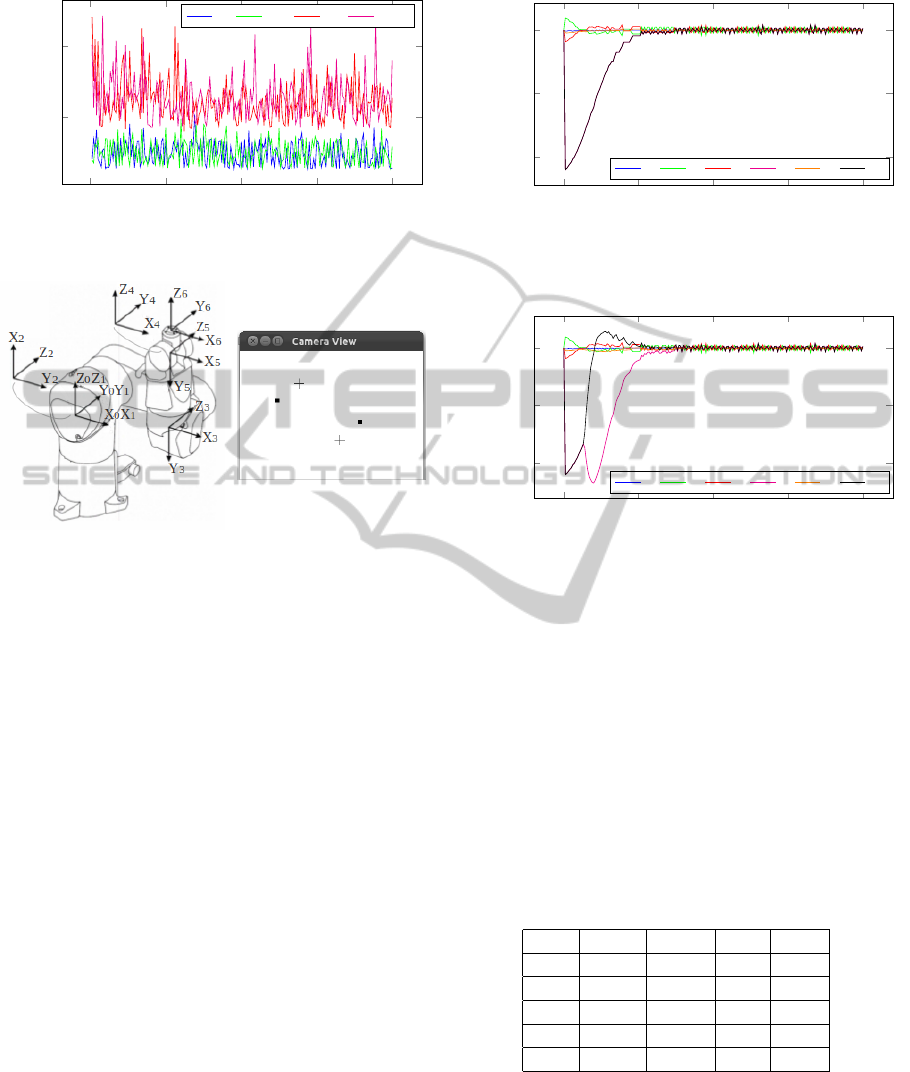
0
50
100
150
200
20
40
Iteration
Time in ms
Modes execution time
VS VSL VSI VSIL
Figure 8: Visuomotor module computing time.
(a)
(b)
Figure 9: Robot configuration for testing joint limits avoid-
ance. a) Joint positions in deg: q
1
= 0, q
2
= 90, q
3
= −90,
q
4
= 0, q
5
= 0, q
6
= 0. b) Simulated view, dots are the cur-
rent feature locations and crosses are the desired locations.
the z axis of the camera frame. The simulated camera
view is shown in Figure 9b.
The primary task (moving the robot to the desired
view of the features) can be solved in infinite ways
given the current singularity between joint frames 4
and 6. For testing the limit avoidance control law,
limits of q
6
min
= −5
◦
and q
6
max
= 5
◦
were set to joint
6. As it is shown in Figure 10, if just the primary task
is performed, the control law generated will mostly
operate q
6
and the task will fall in local minima, since
q
6
min
will be reached. On the contrary, as shown in
Figure 11, setting a threshold ρ = 0.5 (which means it
will be active when q
6
< −2.5
◦
or q
6
> 2.5
◦
) solves
the problem and the joint limit is avoided.
Task Learning. The task designed to run over CRR
had two learning phases. In order to assess the cor-
rectness of the cognitive model and the learning algo-
rithm; two experimental sets were defined. In the ex-
perimental set one (ES1), the objective was to teach
the robot to identify when reaching the target. The
ES1 evaluation consisted of five test cases varying the
order of presentation of the clues ”wait” and ”go”. In
all conditions the robot started without prior knowl-
0 1,000 2,000 3,000 4,000
−4
−2
0
Time in ms
Velocity in deg/sec
Evolution of joints velocities for task 1
˙q
1
˙q
2
˙q
3
˙q
4
˙q
5
˙q
6
Figure 10: Simulation of VS primary task.
0 1,000 2,000 3,000 4,000
−4
−2
0
Time in ms
Velocity in deg/sec
Evolution of joints velocities for task 1 and 2.
˙q
1
˙q
2
˙q
3
˙q
4
˙q
5
˙q
6
Figure 11: Simulation of VS avoiding joint limits.
edge (the RL module was reset). The comparison be-
tween a RL and a random police is given in Table 1; as
it can be seen, the robot was able to learn the task. The
experimental set two (ES2) assumes ES1 was accom-
plished, so the agent properly grasped the object and
must now learn where to drop it. The ES2 evaluation
showed the agent was able to quickly learn the task
using RL, and the resulting Q-values are presented in
Table 2. For each test case of both ES1 and ES2, the
first 20 responses of the robot were registered.
Table 1: ES1 evaluation results. RL-S: number of successes
applying a RL policy, RL-C: RL-S/attempts, R-S: number
of successes applying a random policy, R-C: R-S/attempts.
Test RL-S RL-C R-S R-C
C1 17 0.85 8 0.40
C2 18 0.90 11 0.55
C3 17 0.85 12 0.60
C4 18 0.90 9 0.45
C5 18 0.90 10 0.50
7 CONCLUSIONS
This work started from the interest in developing
cognitive robotic systems for executing manipulative
AComputationalCognitionandVisualServoingbasedMethodologytoDesignAutomaticManipulativeTasks
219

Table 2: ES2 evaluation results. The robot attempted
to release the object without remembering 5 times (tak-
ing the release-loc-1 and release-loc-2 actions). However,
it learned to maximize the reward by tacking the think-
Remember action, which was selected 15 times. Finally, af-
ter recalling the last location, the agent learned to alternate
between the think-release-loc-2-B and think-release-loc-1-
A actions.
Action Freq. Reward
think-Remember 15 4.9302
think-release-loc-2-A 1 -2.2800
think-release-loc-2-B 7 6.9741
think-release-loc-1-A 7 6.9741
think-release-loc-1-B 0 0.0000
release-loc-2 2 0.6840
release-loc-1 3 0.4332
tasks. To this purpose, an approach emphasizing mul-
tidisciplinary theoretical and technical formulations
was adopted. A methodological proposal for integrat-
ing a psychologically-oriented cognitive architecture
to the visual servoing control technique has been pre-
sented; and resulted in the development of a modular
system capable of auditory and visual perception, de-
cision making, learning and visuomotor coordination.
The evaluation of the case study, showed that CRR
is a system whose operation is adequate for real-time
interactive manipulative applications.
ACKNOWLEDGEMENTS
This research was accomplished thanks to the found-
ing of the National Agency of Research through the
EQUIPEX ROBOTEX project (ANR-10-EQX-44),
of the European Union through the FEDER ROBO-
TEX project 2011-2015, and of the Ecole Centrale of
Nantes.
REFERENCES
(2008). Proceedings of the IROS workshop on Current soft-
ware frameworks in cognitive robotics integrating dif-
ferent computational paradigms. 22 September, Nice,
France.
Arbib, M. A., Metta, G., and van der Smagt, P. P. (2008).
Neurorobotics: From vision to action. In Springer
Handbook of Robotics, pages 1453–1480.
Chaumette, F. and Hutchinson, S. (2006). Visual servo con-
trol, part i: Basic approaches. IEEE Robotics and Au-
tomation Magazine, 13:82–90.
Chaumette, F. and Hutchinson, S. (2007). Visual servo con-
trol, part ii: Advanced approaches. IEEE Robotics and
Automation Magazine, 14(1):109–118.
Corke, P. I. (2011). Robotics, Vision & Control: Fundamen-
tal Algorithms in Matlab. Springer.
Duch, W., Oentaryo, R. J., and Pasquier, M. (2008). Cogni-
tive architectures: Where do we go from here? In (iro,
2008), pages 122–136. 22 September, Nice, France.
Hanford, S. and Long, L. (2011). A cognitive robotic system
based on the Soar cognitive architecture for mobile
robot navigation, search, and mapping missions. PhD
thesis, Aerospace Engineering, University Park, Pa.,
USA.
Huelse, M. and Hild, M. (2008). A brief introduction to
current software frameworks in cognitive robotics in-
tegrating different computational paradigms. In (iro,
2008). 22 September, Nice, France.
Kaelbling, L., Littman, M., and Moore, A. (1996). Rein-
forcement learning: A survey. Journal of Artificial
Intelligence Research, 4:237–285.
Kelley, T. D. (2003). Symbolic and sub-symbolic represen-
tations in computational models of human cognition:
What can be learned from biology? Theory & Psy-
chology, 13(6):847–860.
Khalil, W. and Creusot, D. (1997). Symoro+: A sys-
tem for the symbolic modelling of robots. Robotica,
15(2):153–161.
Marchand, E., Chaumette, F., and Rizzo, A. (1996). Using
the task function approach to avoid robot joint lim-
its and kinematic singularities in visual servoing. In
IEEE/RSJ Int. Conf. on Intelligent Robots and Sys-
tems, IROS’96, volume 3, pages 1083–1090, Osaka,
Japan.
Newell, A. (1994). Unified Theories of Cognition. William
James Lectures. Harvard University Press.
O’Reilly, R. and Munakata, Y. (2000). Computational Ex-
plorations in Cognitive Neuroscience: Understanding
the Mind by Simulating the Brain. Bradford Books.
Mit Press.
Pratt, W. (2007). Digital Image Processing: PIKS Scientific
Inside. Wiley-Interscience publication. Wiley.
Sun, R. (2009). Multi-agent systems for society. chapter
Cognitive Architectures and Multi-agent Social Sim-
ulation, pages 7–21. Springer-Verlag, Berlin, Heidel-
berg.
ICINCO2013-10thInternationalConferenceonInformaticsinControl,AutomationandRobotics
220
