
Detection of Hot Pipe Defects using IR Thermography
Kwae Hwan Yoo
1
, Ju Hyun Kim
1
, Man Gyun Na
1
, Jin Weon Kim
1
Kyeong Suk Kim
2
and Chang-Doo Kee
3
1
Department of Nuclear Engineering, Chosun University, 309 Pilmun-daero, Dong-gu, Gwangju, Korea
2
Department of Mechanical Design Engineering, Chosun University, 309 Pilmun-daero, Dong-gu, Gwangju, Korea
3
School of Mechanical Engineering, Chonnam National Univ., 77 Yongbong-ro, Buk-gu, Gwangju, Korea
Keywords: Infrared Thermography, Wall-thinned Defects, Infrared Camera, Cooling Device, Finite Element Analysis
(FEA), Onpower Inspection.
Abstract: Wall-thinned defects, which are attributable to acceleration of corrosion that is occurred by fluid flow in the
inner pipe, appear in various structures of the secondary system in nuclear power plants (NPPs), playing a
role as a major factor to degrade integrity of pipes. It is required to manage wall-thinned defects not only
when the NPP is under maintenance but also when the NPP is in normal operation. To this end, this paper
developed a test technique to manage such wall-thinned defects based on temperature difference on surface
of hot pipe with use of infrared thermography and cooling device. Finite element analysis (FEA) was
conducted to examine tendency of and test conditions for cooling experiment. Based on the FEA results,
equipment was configured before the cooling experiment was conducted. Then, infrared camera was used to
detect defects in the inner pipe of the pipe specimen that had artificially induced defects. The infrared
thermography developed in this study is expected to help resolve issues related to limitations on the non-
destructive inspection that is currently conducted for NPP’s secondary system and expected to be very
useful on the NPP site.
1 INTRODUCTION
Recently, an increasing number of nuclear power
plants (NPPs) have deteriorated due to long-term
operation, which has led to increase in the number of
cases where NPP operation comes to a stop due to
problems in facilities of NPP’s secondary system.
Such cases show that fatigue, corrosion and wall
thinning cause problems in various structures of
NPP’s secondary system. Among these factors, wall-
thinned defects are attributable to acceleration of
corrosion that is occurred by fluid flow in the inner
pipe. The wall-thinned defects can be found
frequently in carbon steel pipe that has the low
content of chromium (Cr). Such wall-thinned defects
can lead to damage without warning sign in advance
while they can be found frequently in base material
part. Therefore, they are known to be one of the
major factors that degrade integrity of pipe.
A systematic management of wall-thinned
defects requires inspection that is conducted on a
regular basis. In particular, the systematic
managemet requires a close inspection even when
the NPP is in operation. The secondary system of the
NPP is the place to which operator or workers get an
access for their work frequently. Unexpected
damage to pipe may cause social impact that cannot
be compared with loss of or damage to person,
which demonstrates the importance of systematic
management of wall-thinned defects. Consequently,
much attention has been paid to non-destructive
inspection in order to examine integrity of major
facilities while there is an increasing demand on the
non-destructive inspection that is relatively safe and
enables conducting measurement in a quick and easy
way.
Currently, various kinds of non-destructive
inspections are conducted such as ultrasonic testing
(UT), eddy current testing (ECT) and magnetic
particle testing (MT). Such non-destructive
inspections include infrared thermography. The
infrared thermography is expected to help resolve
issues related to limitations on the existing non-
destructive inspection because it is used to examine
defects based on measurement of temperature
difference between defect part and non-defect part.
227
Hwan Yoo K., Hyun Kim J., Gyun Na M., Weon Kim J., Suk Kim K. and Kee C..
Detection of Hot Pipe Defects using IR Thermography.
DOI: 10.5220/0004481602270234
In Proceedings of the 10th International Conference on Informatics in Control, Automation and Robotics (ICINCO-2013), pages 227-234
ISBN: 978-989-8565-70-9
Copyright
c
2013 SCITEPRESS (Science and Technology Publications, Lda.)

The infrared thermography is also expected to be
very useful on the site.
Against this background, this study used infrared
thermography to develop cooling device and a
reliable test technique in order to detect wall-thinned
defects in the inner pipe of the NPP that was in
normal operation, which is expected to facilitate
maintenance of plumbing fixtures of NPP’s
secondary system. The results of this study will be
used as basic data for inspection of wall-thinned
defects.
2 THEORETICAL
BACKGROUND
2.1 Infrared Thermography
When an object is cooled from the outside, thermal
diffusion is disturbed on surface of target depending
on existence of defects inside the target. In this case,
insulation effect by defects inside the target causes
temperature difference on the target surface. Infrared
thermography is used to measure temperature on the
surface of target and convert the measurement
results to image before providing image in real time.
Based on the real-time image obtained by using
infrared camera (IR camera), it is possible to
measure shape and location of the defects inside the
target.
Infrared thermography has the following features:
Non-contact technique
Full-field image of stress
Ability to measure energy loss
Easy analysis of results thanks to visual effects
Currently, infrared thermography is applied to
military field, stress analysis, welding monitoring,
evaluation of heat transfer characteristics,
deterioration diagnosis of power facilities, defect
inspection in the composites, and medical diagnosis.
2.2 Theory
All of the objects have temperature that is above the
absolute zero while they emit radiant energy that
corresponds to their temperature.
25
/
(, ) 2
1
hc kT
dR T hc
d
e
(1)
Plank’s constant
34
6.626 10
hJs
Boltzmann’s constant
23
1.380546 10
k
Speed of light
81
2.998 10
cms
The equation (1) describes the Plank’s theory of
black body radiation. According to the theory, a
simple relationship is established between
characteristics of black body radiation (energy
intensity and wavelength) and temperature of black
body. Moreover, radiation amount of wavelength
that is emitted per unit time from black body radiator
is determined only by temperature, which is
characteristic of black body radiation. The
characteristic can be used to calculate temperature of
black body. Infrared thermography enables
measuring amount of emitted energy to provide
temperature image based on the correlation between
amount of detected energy and temperature.
4
0
(,)
t
dR T
R
T
d
(2)
Steffan-Boltzmann’s constant
822
5.67 10 /
WmK
The equation (2) describes the Stefan-Boltzmann’s
law. This theory states that the total energy radiated
per unit surface area of a black body and per unit
time is directly proportional to the fourth power of
absolute temperature T. In this case, T represents the
absolute temperature K of an object in Kelvin
temperature while Rt represents the reflection
intensity of a black body. Based on the equation (1)
and equation (2) mentioned above, IR camera is
used to measure temperature.
a
b
R
R
(3)
Actual emissivity
a
R
Blackbody emissivity
b
R
Energy emitted from a black body is R
b.
An ideal
black body emitter does not exist in reality. If energy
emitted from a real object is R
a,
the emissivity of
object to black body surface at the same temperature
is expressed in the equation (3). In this case, if it is
=1, an object is called a black body. Therefore,
for metal that has low emissivity, the emissivity can
be kept at 0.95 if matte colour spray, which is close
to a black body, is applied.
3 OPTIMAL COOLING METHOD
3.1 Cooling Method
In an NPP that is in normal operation, pipes are
ICINCO2013-10thInternationalConferenceonInformaticsinControl,AutomationandRobotics
228

covered with insulators and in high temperature,
transferring heat up to the surface of insulators.
When cooling device is used to cool the pipes in
high temperature, thermal diffusion is disturbed
depending on existence of defects in inside of the
pipes. Insulation effects by defects cause difference
in temperature locally on surface of the pipes. When
IR camera is used to obtain thermal image of the
pipes where such temperature difference occurred,
defects in the pipes are shown in image depending
on existence of defects. Therefore, after examining
various cooling methods and investigating
applicability of such methods, the authors found out
the optimal cooling method to detect defects in
NPP’s pipes with use of infrared thermography.
3.1.1 Tube Air Cooler
A tube air cooler is a cooling device where pathway
of air current is narrowed to increase fluid velocity
as compressed air rotates in high speed, which aims
at separating hot air current from cool air current.
The tube air cooler uses compressed air in a general
compressor to cool air readily. In addition, the
cooler is fundamentally safe because refrigerant,
electricity or any chemicals are not used for the
cooler. The cooler is effective specially for local
cooling even though it has low capacity. However,
the cooler has some drawbacks because it requires
an additional equipment to use compressed air and
needs to be installed with equipment that produces
compressed air in order to be used portably.
3.1.2 Air-cooling and Water-cooling Coolers
A cooler is a device that converts high-temperature
high-pressure gaseous refrigerant to low-temperature
liquid refrigerant. Gaseous refrigerant containing
heat that is taken away from evaporator gets cooled
as it passes through condenser. Therefore, heat is
released to the outside as the gaseous refrigerant is
turned to the liquid refrigerant. Cooler can be
classified to air-cooling cooler and water-cooling
cooler. The air-cooling cooler has the excellent
cooling capability as it prevents degradation of
cooling function that is attributable to increase in
room temperature. Moreover, the air-cooling cooler
enables keeping temperature constant precisely and
can be adjusted in the wide range of use. The water-
cooling cooler uses water from a cooling tower to
work in the condensation cooling method. It
minimizes indoor noise and shows the higher
cooling efficiency than the air-cooling cooler.
3.1.3 Heat Pipe-type Cooler
A heat pipe-type cooler is a cooling device that
transfers heat in large quantity to condenser prior to
using the pin installed in the condenser for cooling
through natural convection or forced convection.
The heat pipe-type cooler uses working fluid of FC-
27 in the maximum thermal load of 1.5 ㎾. In
addition, it has the operating temperature of –
30~120℃ with the high cooling efficiency. Since
water quantity in heat pipe can be adjusted, the heat
pipe-type cooler can be manufactured in various
forms. However, the heat pipe-type cooler has
drawbacks that it takes longer time for cooling than
other coolers and requires the installation of an
additional fan to increase cooling efficiency.
3.1.4 Fan Cooler
A fan is a device that stirs up the wind as wings
installed on the axis of electric motor rotate. The fan
can be classified to desk fan, ventilating fan and
stand fan depending on shape and purpose of use.
Major parts of the fan include stand, pillar, motor,
and wing. It can be adjusted quite freely according
to angle and direction of movement (up and down or
right and left). The pillar of the fan also can be
adjusted upwardly or downwardly. The fan has the
front-side control panel that enables an easy control
as all of the devices are installed on the front side of
stand. The fan can be also classified to turbo fan,
limit fan and sirocco fan depending on shape of
wing. The turbo fan has the wing that its tip is bent
to the backward of rotation direction, which includes
the one with curved wing and the one with straight
wing. The turbo fan shows the high efficiency and
can be operated relatively quietly even at a high
speed. The limit fan is an upgraded version of the
turbo fan and the sirocco fan. It has the streamlined
wing that is manufactured by folding a thin plate.
Therefore, the limit fan can be rotated in a high
speed with low noise. The sirocco fan has a bent
shape as the tip of wing is bent toward the rotation
direction. Compared to other types of fans in the
same capacity, the sirocco fan features the
significantly low number of rotation.
3.2 Selection of a Cooling Method
In this study, the optimal cooling method was
selected to obtain thermal image of defects in
geometric shape in an easier and quicker way with a
view to examining defect size and depth from
DetectionofHotPipeDefectsusingIRThermography
229

surface. The previous cooling methods include the
method for cooling a pipe with use of a cooler, a
tube air cooler or a heat pipe-type cooler and the
method for installation of a cooling device on the
front side of a pipe with use of a fan. The authors
investigated the characteristics of various cooling
methods among the ones explained above in order to
examine the applicability of such methods. The
results are shown in Table 1.
As shown in Table 1, the cooling method with
use of a fan was evaluated to be the best among the
various cooling methods. The fan cooling method
can be combined with other cooling methods or can
be used independently. Therefore, the fan cooling
method was used in this study to detect wall-thinned
defects inside the pipe based on infrared
thermography.
Table 1: Applicability of Cooling Methods.
Cooling Method Applicability
Air Tube Cooler
As compressed air is used for
cooling, the cooler is cheap and
portable. The cooler has the low
capacity, which is effective for
cooling locally. However, it requires
an additional equipment to use
compressed air. Some limitations are
expected when the cooler is used on
the site of NPPs.
Air-cooling and
Water-cooling
Coolers
The coolers enable keeping
temperature constant precisely and
can be adjusted in the wide range of
use. They show the excellent cooling
capability with high efficiency.
However, the initial cost of
manufacturing is high. They are
heavy and not suitable for being used
portably.
Heat Pipe-type
Cooler
The cooler has the high cooling
efficiency while water quantity in
heat pipe can be adjusted, which
enables being manufactured in
various forms. In addition, the
interval of heat pipe itself can be
adjusted. However, the cooler shows
the high cooling efficiency when it is
installed directly on the target. A fan
needs to be installed additionally.
Fan Cooler
A fan is readily available. Its wing
can be manufactured in various
forms. The angle of the cooler can be
adjusted while rotation speed of the
fan can be adjusted continuously and
freely. In addition, the cooler can be
manufactured to be in light weight.
Therefore, it is believed that the
cooler will be easy to be used
portably.
4 SIMULATION
AND EXPERIMENT
In this study, the fan-type cooling device was
selected as equipment to cool a pipe specimen. Prior
to the testing, a finite element analysis (FEA) was
conducted to investigate the cooling effect of the
selected cooling device as well as the optimal test
conditions. The FEA was conducted by using
ANSYS FLUENT 13.0 while GAMBIT program
was used for generating the mesh that was modelled
to conduct the FEA. In addition, based on the FEA
results, cooling tests were performed to detect
defects inside the pipe specimen.
4.1 Specimen and Equipment
The pipe specimen used for this study has defects
inside for the purpose of cooling test. For the test,
the pipe specimen with 4 inch diameter was
manufactured with the material of Shc.80 ASTM
A106 Gr.B, which was similar to the actual pipe
used in the NPPs. As shown in Figure 1, the pipe
specimen has the total length of 500mm, the
thickness of 7.5mm, and the external diameter of
113mm. On the inner surface, four defects were
created in a constant length. The four defects have
the depth that is 50% and 75% respectively of the
thickness of the pipe specimen. Furthermore, matte
colour spray was applied to the surface of the pipe
specimen in order to ensure the surface emissivity of
0.95, which aimed at minimizing the reflection of
light. Figure 2 shows the pipe specimen that was
manufactured for this study.
A blower fan was used as a cooling device to
cool the pipe specimen. The blower fan has 6 wings
at the maximum wind speed of 16.5m/s. The size of
its wing is 27cm. The blower fan features a uniform
cooling of the pipe specimen.
Figure 1: Design of a pipe specimen.
ICINCO2013-10thInternationalConferenceonInformaticsinControl,AutomationandRobotics
230
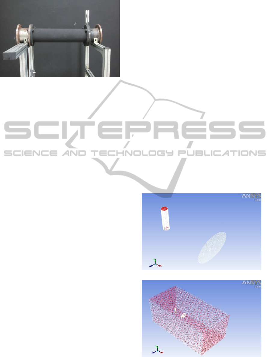
Figure 2: The pipe specimen.
4.2 Simulation Method
In regard to testing for wall-thinned defects inside
the pipe, thermal analysis can be figured out based
on the FEA that uses the numerical technique prior
to experiments. The FEA provides the data to predict
problems in thermal distribution of the pipe
specimen based on analysis of simulation results, to
configure the cooling device that can be applied to
an actual environment, and to investigate the optimal
test conditions.
4.2.1 Specimen Modelling and Boundary
Condition
In this study, the pipe specimen used for the
experiment was ASTM A106 Gr.B that was
frequently used for actual pipe of the NPP’s
secondary system, which was manufactured of
carbon steel. Therefore, pipe modelling for the FEA
was performed under the same conditions as the
ones for pipe specimen that was used to test cooling
devices. Modelling of the pipe specimen was
performed in the total length of 500mm, the
thickness of 7.5mm, and the external diameter of
113mm. Four defects in the two types were created
inside to ensure that they had the depth that was 50%
and 75% respectively of the thickness of the pipe
specimen. Moreover, as matte colour spray was
applied to the surface of the pipe specimen in order
to minimize the reflection of light, reflection
conditions were taken into consideration for the pipe
modelling, which aimed at ensuring that the effects
from emissivity were kept constant while the
reflection of light was minimized.
The basic boundary conditions for the FEA were
established as follows. In order to simplify analysis,
symmetric conditions were set to consider half of the
pipe model. A large amount of thermal state and
fluid conditions were entered for fluid that took each
solid or air as thermal fluid medium. In addition,
temperature (25℃) and humidity for the entire space
were kept constant, excluding those for the pipe
model and the cooling device model.
4.2.2 Cooling Method
This study used the cooling device based on the
principles of a fan. Therefore, in order to conduct the
FEA for the cooling device, the principles of a fan
were applied to cool the pipe model through the
forced convection that was occurred by pressure
difference between surfaces of the fan model and the
pipe model. In addition, as a way to describe a hot
pipe in the NPP that was in normal operation, water
was designed to flow inside the pipe model. Mass
flow rate of water was set at 1kg/sec. Figure 3 (a)
shows the diagrams of the pipe model and the fan
model. Figure 3 (b) shows the meshes that were
created to improve the accuracy of the analysis.
ANSYS FLUENT was used to perform the
simulation of the FEA for a cooling device. The
distance between the fan model and the pipe model
and the pressure difference in the fan model were
adjusted. For simulation conditions, the distance
between the pipe model and the fan model was
adjusted to 1m, 2m and 3m while the pressure
difference in the fan model was set at 100Pa and
(a) Diagrams of Pipe Model and Fan Model
(b) Creation of Mesh
Figure 3: Configuration of Modelled Fan and Pipe
Specimen.
DetectionofHotPipeDefectsusingIRThermography
231

150Pa. The temperature of water flowing inside the
pipe model was adjusted to 100Ԩ and 200Ԩ.
4.3 Simulation Results
The FEA was made based on the image at 30
seconds that showed defects the most clearly among
the results of simulation that was conducted for 60
seconds. Figure 4 shows the results of simulations
that were performed when the surface pressure
difference between the fan model and the pipe
model was 100Pa, the temperature of the pipe model
was 100℃ and 200℃, and the distance between the
pipe model and the fan model was adjusted to 1m,
2m and 3m. The deviation of temperature in the
defect part was observed to be conspicuous under all
of the test conditions regardless of distance between
the pipe model and the fan model. In addition,
Figure 5 shows the results of simulations that were
performed when the surface pressure difference
between the fan model and the pipe model was
150Pa, the temperature of the pipe model was 100℃
and 200℃, and the distance between the pipe model
and the fan model was adjusted to 1m, 2m and 3m.
The shape of defects was observed with the naked
eye while the defects looked clearer as the pressure
difference in the fan model increased regardless of
depth of defects. Moreover, as the distance between
the pipe model and the fan model was shorter such
as 1m and 2m, the defects became more distinct.
(a) 100Ԩ, 1m (b) 100Ԩ, 2m (c) 100Ԩ, 3m
(d) 200Ԩ, 1m (e) 200Ԩ, 2m (f) 200Ԩ, 3m
Figure 4: Pressure Difference of 100Pa in Fan Model.
(a) 100Ԩ, 1m (b) 100Ԩ, 2m (c) 100Ԩ, 3m
(d) 200℃, 1m (e) 200℃, 2m (f) 200℃, 3m
Figure 5: Pressure Difference of 150Pa in Fan Model.
Consequently, the FEA simulation could confirm the
cooling effects of the fan cooling device. The
optimal test conditions include the pressure
difference in the fan at 150Pa and the close distance
such as 1m and 2m between the pipe specimen and
the fan cooling device.
4.4 Experiment Method
The FEA that was conducted based on the numerical
technique prior to the experiment could confirm the
cooling effects of a cooling device. In this study, an
IR camera and a cooling device were configured
according to the test conditions that were established
based on the FEA results with a view to detect wall-
thinned defects inside the manufactured pipe
specimen.
The temperature of pipes should be kept high
since it is assumed that inspections are conducted for
wall-thinned defects inside pipes of the NPP that is
in normal operation. Therefore, the experiment for
this study was conducted when the temperature of
the pipe specimen was kept high. To this end, a
heating device in the pipe was manufactured before
it would be inserted to the inside of the pipe
specimen. The inner heating device was
manufactured to ensure that the support was close to
the inner wall of the pipe specimen and that the
support could be wrapped up with two heating tapes
that could heat up to 400℃. Figure 6 shows the inner
heating device that was used to implement a hot pipe.
In order to verify the heating performance of the
inner heating device, the device was installed inside
the pipe specimen before being heated up. Then, an
IR camera was used to measure temperature
distribution. The measurement results showed that
the surface temperature of the 4-inch pipe specimen
was kept at 142℃~150.35℃ depending on location
when the temperature of two heating tapes was set at
320℃ for each. Figure 7 shows the surface
temperature of the pipe specimen that was measured
by using the IR camera when the maximum surface
temperature of the pipe specimen was kept at 150℃.
According to the measurement results, the highest
temperature was observed in the center of the pipe
specimen while the temperature tended to decrease
as the distance from the center increased.
As shown in Figure 8, the authors configured the
experimental equipment for detection of wall-
thinned defects inside the pipe that included an IR
camera, a fan, a pipe specimen, heating tapes, a
heating tape controller, and a PC. The experiment
ICINCO2013-10thInternationalConferenceonInformaticsinControl,AutomationandRobotics
232
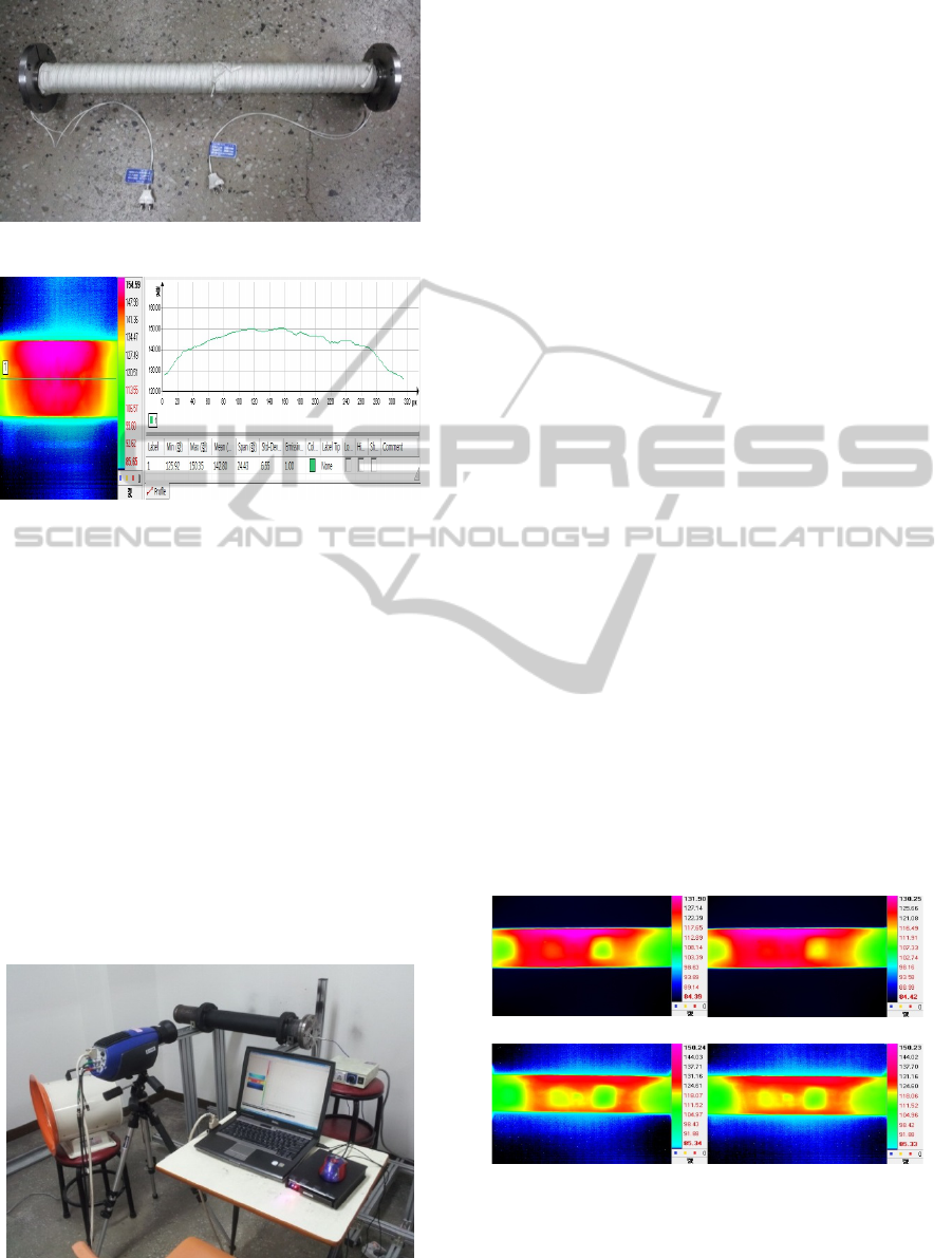
Figure 6: Inner Heating Device for a Pipe Specimen.
Figure 7: Temperature Distribution in an Inner Heating
Device.
was conducted in a closed space while the
temperature in the laboratory was kept constant at
25℃ with use of an air conditioner.
In order to describe the pipe of the NPP that was
in normal operation, the inner heating device was
used to maintain the temperature of the pipe
specimen at 150Ԩ while the experiments were
conducted with variables that included the distance
between the pipe specimen and the fan and the
number of fans. The distance between the pipe
specimen and the IR camera was fixed at 1m while
the distance between the pipe specimen and the fan
was adjusted to 1m and 2m. In addition, the number
of fans was adjusted to 1 and 2 while each
experiment was conducted for 120 seconds.
Figure 8: Experimental Equipment with Use of Cooling
Device.
4.5 Experiment Results
Cooling tests for detection of wall-thinned defects
inside the pipes of the NPPs that were in normal
operation were conducted as an heating device was
inserted to the inside of the pipe specimen at the
temperature of 150Ԩ, which aimed at implementing
high temperature. In addition, the cooling tests were
conducted as the number of fans was adjusted to 1
and 2 and the distance between the pipe specimen
and the fan was adjusted to 1m and 2m based on the
FEA results.
Figure 9 (a) and Figure 9 (b) show the
experiment results when one fan was used with the
distance between the pipe specimen and the fan
adjusted to 1m, 2m and 3m. According to the
experiment results, when the distance was 1m, the
cooling effect was confirmed to be at around 34Ԩ.
When the distance was 2m, the cooling effect was
confirmed to be at around 28Ԩ. The defects created
at the 75% depth inside the pipe specimen were
detected at the distance of 2m. The defects were
detected more clearly as the distance between the
pipe specimen and the fan became shorter. Figure 9
(c) and Figure 9 (d) show the experiment results
when two fans were used to cool the pipe specimen
in the distance of 1m and 2m. When the distance
was 1m, the cooling effect was confirmed to be at
around 32Ԩ. When the distance was 2m, the cooling
effect was confirmed to be at around 27Ԩ. In
addition, it was possible to detect the defects that
were artificially created not only with the 75% depth
but also with the 50% depth inside the pipe
specimen. The defects were detected more
conspicuously as the distance between the pipe
specimen and the cooling device became shorter.
(a) One Fan in 1m (b) One Fan in 2m
(c) Two Fans in 1m (d) Two Fans in 2m
Figure 9: Pressure Difference of 150Pa in Fan Model.
DetectionofHotPipeDefectsusingIRThermography
233

5 CONCLUSIONS
In this study, infrared thermography was used to
detect wall-thinned defects inside the pipe of the
NPPs that were in normal operation. The pipe model
and the pipe specimen that had the same physical
properties as those for the actual pipe of the NPP
were used for the FEA and experiment. Moreover,
the size of defects applied to the pipe specimen was
equal to that of defects applied to the pipe model for
the FEA.
According to the results of the FEA that was
conducted to examine the cooling effects of a
cooling device and the optimal test conditions, the
detection capability of defects was predicted to
increase as the distance between the pipe and the fan
decreased and the wind speed of fan increased. The
prediction was applied to the experiment.
Defects could be detected partially in the test that
was conducted by using the cooling device of a fan
based on the FEA results. Unlike the analysis results,
defects with the 75% depth of the pipe thickness
could be detected clearly when the distance between
the pipe specimen and the fan was 1m. In order to
detect wall-thinned defects in the NPP that is in
normal operation based on such results, the distance
between the pipe and the fan should be short such as
1m while the wind speed and air flow of the fan
should be high.
In conclusion, infrared thermography enabled
detecting wall-thinned defects inside the pipe while
it was expected to be very useful on the NPP site
compared to the existing non-destructive inspection.
Moreover, since the infrared thermography
facilitates performing the maintenance of facilities
of the NPPs that are in normal operation or the NPPs
that are in maintenance period, it is expected to
maximize the operation efficiency of NPP facilities
and minimize the energy loss and economic loss that
are attributable to the operation stop.
REFERENCES
Frank, M., Hans, R. and Helmut, S., 2001. Experience
with piping in German NPPs with Respect to Ageing-
Related Aspects, Nuclear Engineering and Design,
Vol. 207, No. 3, pp. 307-316.
G. Gaussorgurs, 1994. Infrared thermography Translated
by S. Chomet, Champmam & Hall.London, pp. 415-
452.
ICINCO2013-10thInternationalConferenceonInformaticsinControl,AutomationandRobotics
234
