
Control System with State Feedback and NN based Load Torque
Feedforward for PMSM with LC Filter Fed by 3-Level NPC Inverter
L. M. Grzesiak
1
and T. Tarczewski
2
1
Institute of Control and Industrial Electronics,Warsaw University of Technology, Koszykowa 75, Warsaw, Poland
2
Institute of Physics, Faculty of Physics, Astronomy and Informatics, Nicolaus Copernicus University,
Grudziadzka 5, Torun, Poland
Keywords: Artificial Neural Network, Load Torque Feedforward, State Feedback Controller, 3-Level Neutral Point
Clamped Inverter, LC Filter, Permanent Magnet Synchronous Motor, Disturbance Observer.
Abstract: This paper presents designing process of the control system with discrete state feedback and neural network
based load torque feedforward for permanent magnet synchronous motor fed by true sine wave 3-level
neutral point clamped inverter with an output LC filter. Our main objective is to reduce the effect of load
torque changes and to improve dynamic behaviour of the motor during load changing. The full state
feedback algorithm has been chosen to control the angular velocity of the motor and to provide true sine
wave of the input motor voltages. It was found that gains of the controller and feedforward path are non-
stationary and depends on the angular velocity. In such a case linearization and decoupling process of the
motor with LC filter is not needed. Simulation results (at the level of 3kW) illustrate the proposed approach.
1 INTRODUCTION
Artificial neural networks (ANN) have been playing
an important role in a motion control systems.
Thanks to the universal approximation property,
ANNs are successfully used for: friction modeling
and compensation (Huang and Tan, 2012),
deadzone function estimation and compensation
(Selmic and Lewis, 2000) as well as adaptive control
(Pajchrowski and Zawirski, 2012).
The control performance of permanent magnet
synchronous motor (PMSM) is influenced by an
external load. This performance can be improved
with the help of the feedforward compensation
(Iwasaki et al., 2012). Although, load torque is non-
measurable variable in a typical motion system, it
can be estimated with the help of the disturbance
observer (Mun-Soo et al., 2001). Proper feedforward
compensation requires suitable formula depends on
control algorithm used.
Electromagnetic torque ripple of PMSM can be
reduced when 3-level Neutral Point Clamped (NPC)
true sine wave inverter with an output LC filter is
used (Tarczewski and Grzesiak, 2012). Non-linear,
non-stationary model of such a system causes, that
the state feedback control is an attractive control
method (Pawlikowski and Grzesiak, 2007).
In this paper control system with discrete state
feedback controller for PMSM fed by true sine
3-level NPC inverter is presented. In order to reduce
the effect of load torque changes and to improve the
dynamic behaviour of PMSM during load variations,
NN based non-stationary feedforward load torque
path is introduced into control system.
A mathematical formula how to calculate an
appropriate non-stationary gain values for a load
torque feedforward path is depicted. Observed load
torque is used as an input signal for the feedforward
path. The discrete full state feedback controller with
an internal input models is designed in order to
control the angular velocity of the PMSM with
respect to zero d-axis component of the current
space vector and to provide true sine wave of the
input motor voltages.
2 MATHEMATICAL MODEL OF
AN ELECTROMECHANICAL
SYSTEM
Considered control system consists of: discrete state
feedback controller with neural network feedforward
path, 3-level NPC inverter with an output LC filter,
259
Grzesiak L. and Tarczewski T..
Control System with State Feedback and NN based Load Torque Feedforward for PMSM with LC Filter Fed by 3-Level NPC Inverter.
DOI: 10.5220/0004484002590267
In Proceedings of the 10th International Conference on Informatics in Control, Automation and Robotics (ICINCO-2013), pages 259-267
ISBN: 978-989-8565-70-9
Copyright
c
2013 SCITEPRESS (Science and Technology Publications, Lda.)

observer and PMSM. Schematic diagram of
proposed control system was shown in figure 1.
Figure 1: Proposed control system.
2.1 Model of PMSM
In order to create mathematical model of PMSM,
following assumptions are made (Pillay and
Krishnan, 1988), (Zawirski, 2005): eddy current and
hysteresis losses are negligible, saturation is
neglected, the back emf is sinusoidal, magnetic
symmetry occurs in the circuit. In an orthogonal d-q
coordinate system that rotates at electrical velocity
ω
k
of the rotor, the expression of the voltage and
flux equation takes the following form (Pillay and
Krishnan, 1988), (Zawirski, 2005):
qm
d
sdsCd
p
t
iRu
d
d
(1)
dm
q
sqsCq
p
t
iRu
d
d
(2)
fsdsd
iL
(3)
sqsq
iL
(4)
where: u
Cd
, u
Cq
, i
sd
, i
sq
, ψ
d
, ψ
q
are space vector
components of voltages, currents and fluxes in d and
q axis, R
s
is resistance of the stator, L
s
is inductance
of the stator, ψ
f
is permanent magnetic flux linkage,
p is the number of pole pairs, ω
m
is rotor angular
velocity.
Cross couplings between d and q axis as well as
the product of an angular velocity and fluxes causes,
that voltage equations (1)-(2) are non-linear.
For a PMSM with a surface mounted magnets,
the electromagnetic torque is proportional to the
quadrature current and it can be expressed as follows
(Pillay and Krishnan, 1988), (Zawirski, 2005):
sqtsqfe
iKipT
2
3
(5)
where K
t
is motor torque constant.
Finally, to complete mathematical model of the
PMSM, the following equation of mechanical
motion have been added (Pillay and Krishnan,
1988), (Zawirski, 2005):
lmme
m
m
TBT
Jt
1
d
d
(6)
where: J
m
is motor moment of inertia, T
l
is load
torque, B
m
is viscous friction.
2.2 Model of Reactance Filter
Similarly to model of PMSM presented above,
model of an output LC filter is described in an
orthogonal d-q coordinate system. The expression of
voltage and current equation takes the following
form (Pawlikowski and Grzesiak, 2007):
CdLqkf
Ld
fLdfid
uiL
t
i
LiRu
d
d
(7)
CqLdkf
Lq
fLqfiq
uiL
t
i
LiRu
d
d
(8)
Cqkf
Cd
fCd
uC
t
u
Ci
d
d
(9)
Cdkf
Cq
fCq
uC
t
u
Ci
d
d
(10)
sdCdLd
iii
(11)
sqCqLq
iii
(12)
where:
u
id
, u
iq
, i
Ld
, i
Lq
are space vector components
of filter input voltages and currents, i
Cd
, i
Cq
are space
vector components of currents in filter capacitance,
R
f
is filter resistance, L
f
is filter inductance, C
f
is
filter capacitance.
2.3 Model of Inverter
Static model of the 3-level NPC inverter can be used
if inverter operates in a linear range, the switching
frequency is much higher than the electrical time
constant of PMSM and if dead time of IGBTs can be
ignored. Model of the inverter can be described as
follows (Grzesiak and Tarczewski, 2013):
pq
pd
p
iq
id
u
u
K
u
u
(13)
where:
u
pd
, u
pq
are space vector components of
inverter control voltages, K
p
is gain coefficient of
inverter. Presented in (Grzesiak and Tarczewski,
2013) simulation as well as experimental test results
show, that described model of the inverter does not
introduce any significant error.
ICINCO2013-10thInternationalConferenceonInformaticsinControl,AutomationandRobotics
260

3 DISCRETE STATE FEEDBACK
CONTROLLER
Non-linear terms in equations (1)-(2) as well as in
equations (7)-(10) cause that the state feedback
control is an attractive approach to control described
in a previous section electromechanical system.
3.1 State-space Representation
of the System
In order to design state feedback controller, model of
electromechanical system (1)-(13) should be
rewritten in a form of the state equation:
d
t
k
EBuxA
x
)(
d
d
(14)
where:
,
aa
aaaa
aaa
aaa
aaa
aaa
aaa
k
98
7625
265
424
424
312
321
00000
000
0000
0000
0000
0000
0000
)(
A
,Td,
J
,
u
u
,
L
K
L
K
,ωiiuuii
l
m
pq
pd
f
p
f
p
msqsdCqCdLqLd
1
000000
000000
000000
][
T
T
T
E
uB
x
m
m
m
t
s
f
s
s
sf
f
km
f
f
J
B
a,
J
K
a,
L
p
a
,
L
R
a,
L
a,
C
a
,
L
a,pa,
L
R
a
987
654
321
11
1
3.2 An Internal Input Model
In the proposed control algorithm steady state error
of the angular velocity is caused by step variations
of the reference velocity and load torque. It could be
eliminated by introducing an internal model of the
reference input (Grzesiak and Tarczewski, 2013).
Control strategy with zero d-axis component of the
current space vector is the most popular in PMSM
(Zawirski, 2005). An internal model of the reference
direct current has been added to ensure control
strategy described above.
An augmented state equation, after introduction
the internal input model and assumption, that
external load torque
T
l
is omitted, takes the
following form:
iiiiki
i
t
rFuBxA
x
)(
d
d
(15)
where:
,
aa
aaaa
aaa
aaa
aaa
aaa
aaa
k
010000000
0000000
00000
000010000
000000
000000
000000
000000
000000
)(
98
7625
265
424
424
312
321
i
A
100000000
000100000
00000000
00000000
][
T
*
*
T
T
i
m
sd
i
f
p
f
p
i
msqisdCqCdLqLdi
,
i
,
L
K
L
K
,eωieiuuii
F
rB
x
New state variable e
i
introduced in an augmented
state equation (15) corresponds to the integral of the
direct current:
t
sdsdi
diite
0
*
)]()([)(
(16)
where
i
*
sd
is the reference value of the direct current.
Similarly, state variable
e
ω
corresponds to the
integral of the angular velocity error:
t
mm
dte
0
*
)]()([)(
(17)
where
ω
*
m
is the reference value of the angular
velocity.
ControlSystemwithStateFeedbackandNNbasedLoadTorqueFeedforwardforPMSMwithLCFilterFedby3-Level
NPCInverter
261

3.3 Non-stationary Discrete Controller
The control law for system described by an
augmented state equation (15) can be computed
from the following formula:
)()()()(
)()()()()(
tete
ttt
ωkeωikei
kxik
KK
xKxKu
(18)
where: K(
ω
k
), K
x
(ω
k
), K
ei
(ω
k
), K
eω
(ω
k
) are non-
stationary gain matrices of the state feedback
controller.
In order to design discrete state feedback
controller suitable to implement in a DSP system,
the control law presented above must be rewritten in
a discrete form:
)()()()(
)()()()()(
nene
nnn
ωkeωikei
kxk
KK
xKxKu
i
(19)
where n is an index of the discrete sampling time.
By using the backward Euler integration
algorithm, discrete form of the state variables e
i
and
e
ω
were obtained:
)]()([)1()(
*
niniTnene
sdsdsii
(20)
)]()([)1()(
*
nnTnene
mms
(21)
where T
s
is the sampling interval.
The discrete linear-quadratic optimization
method (Tewari, 2002) was used to calculate gain
coefficients of the state feedback controller at the
operating points defined by the actual value of the
angular velocity ω
k
[-942; 942] rad/s. The Matlab
Control System Toolbox has been used to calculate
appropriate matrices.
In order to compute non-stationary gain values of
the controller, the following penalty matrices has
been assigned:
])diag([
])diag([
987654321
21
iiiiiiiiii
iii
qqqqqqqqq
,rr
Q
R
(22)
where: r
i1
= r
i2
= 3×10
−1
, q
i1
= q
i2
= q
i3
= q
i4
= 1×10
−5
,
q
i5
= 5,7×10
1
, q
i6
= 1×10
7
, q
i7
= 7,6×10
−1
,
q
i8
= 1×10
−2
, q
i9
= 1,64×10
2
.
Values of the gain matrices depicted above were
selected manually in order to: provide zero steady
state angular velocity error for step angular velocity
reference change as well as load torque step
variations, achieve twice the rated current of PMSM
(i
sn
= 5,8 A) during the step change of the reference
angular velocity from 0 rad/s to 70π rad/s with the
rated load torque (T
ln
= 8,8 Nm). The assumptions
presented above determine the maximum dynamics
of the designed control system.
Matlab’s polyfit and polyval commands were
used to determine the mathematical functions that
approximate dependencies between the controller’s
gain and the angular velocity.
Based on the simulation test results it was found
that: coefficients k
d2
(ω
k
), k
q1
(ω
k
), k
q3
(ω
k
), k
q5
(ω
k
) and
k
q6
(ω
k
) have the negligible impact of the control
process and can be replaced by zeros; coefficients
k
d1
(ω
k
), k
d3
(ω
k
), k
d5
(ω
k
), k
d6
(ω
k
), k
q2
(ω
k
), k
q4
(ω
k
),
k
q7
(ω
k
), k
q8
(ω
k
) and k
q9
(ω
k
) can be replaced by
constant values (independent of the angular
velocity). Constant gain coefficients were computed
by using mean function implemented in the Matlab
environment. Coefficients k
d4
(ω
k
), k
d7
(ω
k
), k
d8
(ω
k
),
k
d9
(ω
k
) should be implemented as the following
linear functions:
kkd
k
-7
4
10,297)(
(23)
kkd
k
-6
8
10,287)(
(24)
kkd
k
-5
7
10,515)(
(25)
kkd
k
-4
9
10,816)(
(26)
Finally, gain coefficients of the discrete state
feedback controller computed for the system with
parameters given in table 1 and for penalty matrices
(22) are as follows:
,
0,053)(
0,31)(
00,62
0,004)(
00,0077
0,10
00,13
8
7
4
T
kd
kd
kd
k
k
k
k
x
K
(27)
5,71
)(
,
0
298,76
9 kd
kk
k
ωi
ee
KK
(28)
Table 1: The basic parameters of the system.
Parameter Value Unit
R
f
3
10
-2
Ω
L
f
2
10
-3
H
C
f
6
10
-6
F
R
s
1,05 Ω
L
s
9,5
10
-3
H
K
t
1,635 Nm/A
J
m
6,2
10
-4
kgm
2
B
m
1,4
10
-3
Nms/rad
K
p
291
p 3
ICINCO2013-10thInternationalConferenceonInformaticsinControl,AutomationandRobotics
262
4 FEEDFORWARD LOAD
TORQUE COMPENSATION
Dynamic properties of the discrete state feedback
controller can be improved by using the disturbance
signals (Tewari, 2002). In the designed control
system, load torque can be used for a feedforward
compensation.
4.1 Feedforward Computation
In order to introduce feedforward path, residual
model of state equation (14) should be considered
(Lee et al., 1994), (Pawlikowski and Grzesiak,
2007):
uBxA
x
~~
)(
d
~
d
k
t
(29)
where:
ssss
, uuuxxx
~
~
(30)
are deviations from the steady state.
It can be seen, that presented above residual
model is non-stationary due to the presence of
ω
k
in
the state matrix. It was assumed that disturbance
d
remains constant for deviations from steady state, so
it is not present in residual model (29).
The control law for the non-stationary residual
model can be formulated as follows:
ss
ss
kxkx
u
x
IKxKu ])([)(
(31)
where I is an identity matrix with an appropriate
dimension. The column vector from the right side of
the control law (31) can be computed from the
following form of the state equation in steady state:
d
k
ss
ss
EG
u
x
1
)(
(32)
where:
])([)( BAG
kk
(33)
After substituting of (32) into (31), the control law
can be rearranged as follows:
d
kkk
EGIKxKu
xx
1
)()()(
(34)
Denoting the second component of the equation (34)
as:
EGIKK
1
)(])([)(
kkxkd
(35)
one can write the control law with the feedforward
path:
d
kdkx
)()(
KxKu
(36)
Finally, the discrete form of the control law with an
internal input model of the reference signals and
with the feedforward path takes the following form:
)()()()(
)()()()()(
ndne
nenn
kdke
ikeikx
KK
KxKu
(37)
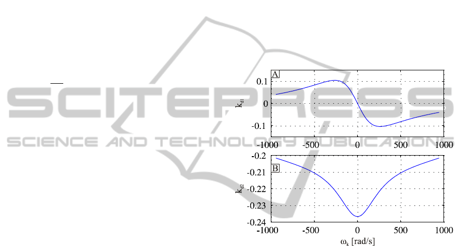
After evaluating equation (35), it was found that the
relationships between the angular velocity
ω
k
and
feedforward gain coefficients:
K
d
T
(ω
k
) = [k
d1
(ω
k
) k
d2
(ω
k
)] are nonlinear (figure 2).
Figure 2: Values of the feedforward coefficients.
4.2 Neural Network Approximation
Since artificial neural networks have an inherent
capability of learning and approximating nonlinear
functions (Huang and Tan, 2012), it is attractive to
apply them to approximate nonlinear dependencies
presented in figure 2.
It was found that feedforward coefficients can be
successfully approximated with the help of the
feedforward backpropagation artificial neural
network. For a neural network with 7 neurons in the
first layer and 2 neurons in the output layer,
satisfactory level of approximation (mean square
error less than 1×10
-7
) was achieved after 417
epochs. Schematic diagram of the designed and
trained in a Matlab environment neural network
approximator is presented in figure 3.
ControlSystemwithStateFeedbackandNNbasedLoadTorqueFeedforwardforPMSMwithLCFilterFedby3-Level
NPCInverter
263
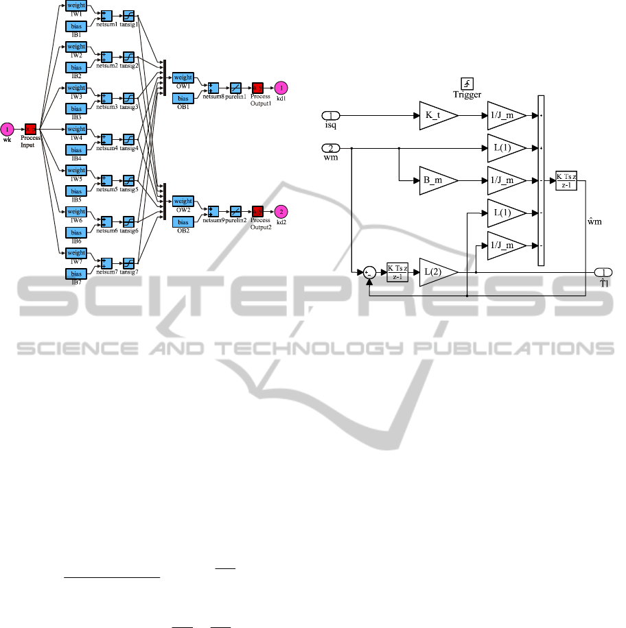
Figure 3: Neural network approximator.
5 LOAD TORQUE OBSERVER
In order to design the control system with a
feedforward load torque compensation, a non-
measured load torque should be estimated with the
help of the observer. The discrete state equation that
describes the dynamics of the system takes the
following form (Mun-Soo et al., 2001):
)()()(
nunn
ooooo
BxAx
(38)
)()(
nny
o oo
xC
(39)
where:
]01[),()(
,
00
1
,
)(
)(
)(
,
0
,
)1()(
)(
o
oo
o
oo
o
C
Ax
B
xx
x
ninu
JJ
B
nT
n
n
J
K
T
nn
n
sqo
mm
m
l
m
m
t
s
(40)
For system (38)-(40) the following equation of the
discrete load torque observer can be formulated
(Luenberger, 1971):
)](
ˆ
)([
)()(
ˆ
)(
ˆ
nny
nunn
o
o
oo
oooo
xCL
BxAx
(41)
where:
2
1
,
)(
ˆ
)(
ˆ
)(
ˆ
l
l
L
nT
n
n
l
m
o
x
(42)
An observable values are depicted in
o
x
ˆ
while L is
a gain matrix of the designed observer. A schematic
diagram of implemented in Simulink discrete load
torque observer is shown in figure 4.
Figure 4: Block diagram of the load torque observer.
The goal of the designed load torque observer is to
provide an estimate
o
x
ˆ
so that
oo
xx
ˆ
for
t
. Because system (41) is fully observable, we
can find L matrix so that the tracking error is
asymptotically stable. Therefore, the observer design
process is reduced to finding the gain matrix L so
that the roots of the system (41) characteristic
equation lie in the left half-plane. Gain matrix of the
load torque observer was determined with the help
of Matlab’s
place formula. For the pole locations:
io
33
2/1
101103
(43)
that guarantee the proper dynamics of the observer,
values of the gain matrix
L
are as follows:
3
2
3
1
102,6,106 ll
(44)
6 CONTROL SYSTEM
WITH DISCRETE STATE
FEEDBACK CONTROLLER
AND LOAD TORQUE
FEEDFORWARD
The proposed control system was tested in the
Matlab/Simulink environment with the help of the
Plecs blockset. The results obtained for control
system with neural network based load torque
feedforward path were compared with the results
achieved for the state feedback based control system
without feedforward.
ICINCO2013-10thInternationalConferenceonInformaticsinControl,AutomationandRobotics
264
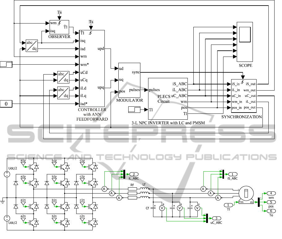
Figure 5: Schematic diagram of the designed control system.
Figure 6: Schematic diagram of the PMSM with 3-level NPC inverter and LC filter.
6.1 Model of the proposed Control
System
Schematic diagram of the designed control system
was presented in figure 5.
Described in previous sections discrete state
feedback controller as well as load torque observer
were implemented in triggered subsystems in order
to ensure proper generation of discrete control and
estimate signals respectively. The sampling interval
was set to
T
s
= 100 μs (the switching frequency is
equal to
f
s
= 10 kHz).
In order to realize measurements in a midpoint of
the PWM pulse length, triggered synchronization
block was used.
Shown in figure 6 model of PMSM with 3-level
NPC inverter as well as LC filter was implemented
in the Plecs software.
Carrier-based sinusoidal PWM with level shifted
triangular carriers modulation method was used to
control switches in the 3-level NPC inverter
(Rodriguez et al., 2010).
For the proper operation of the designed control
system the resonance frequency of the LC filter
(
f
r
= 1453 Hz) was set to be almost ten times higher
than the rated frequency of the motor (
f
m
= 150 Hz)
and almost seven times lower than the switching
frequency (Steinke, 1999).
6.2 Simulation Test Results
Simulation test results of the proposed control
system were presented in figure 7.
Depicted in figure 7.A the angular velocity step
responses of the control system show, that by using
state feedback controller with load torque
feedforward path, improvement of the dynamics
could be achieved during the transient caused by the
ControlSystemwithStateFeedbackandNNbasedLoadTorqueFeedforwardforPMSMwithLCFilterFedby3-Level
NPCInverter
265
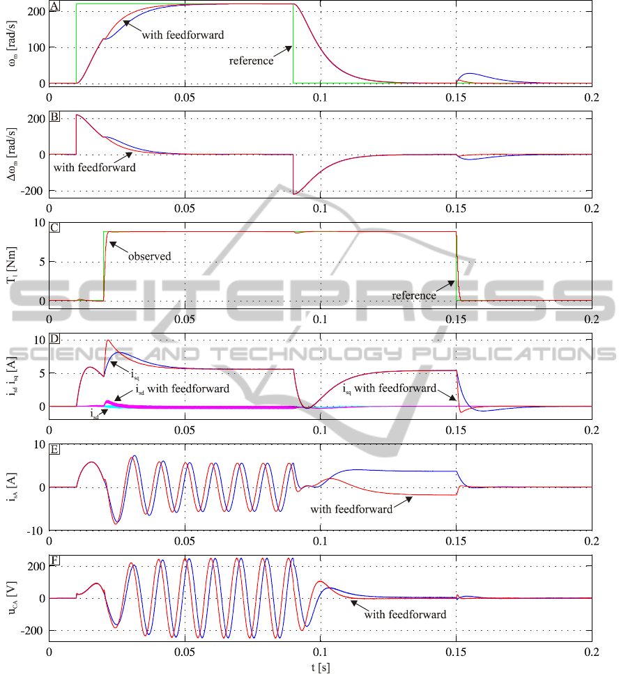
Figure 7: Simulation test results.
load torque step change. It can be seen, that the
angular velocity error caused by load torque step
changes at
t = 20 ms and at t = 150 ms is smaller,
when feedforward path is used. The use of the load
torque feedforward path minimise the dynamic error
by the transient.
The proper operation of the load torque observer
is presented in figure 7.C. An actual value of the
load torque is estimated with good dynamics and
without steady state error.
It can be seen from figure 7.D, that the
q-axis
component of the current space vector is responsible
for producing electromagnetic torque. PMSM
operates with control strategy based on zero
d-axis
component of the current space vector.
By using of the LC filter, sinusoidal waveform of
the input motor voltage can be obtained
(figure 7.E). In this case, electromagnetic torque
ripple reduction can be achieved.
ICINCO2013-10thInternationalConferenceonInformaticsinControl,AutomationandRobotics
266

7 CONCLUSIONS
This paper presents discrete full state feedback non-
stationary controller with neural network based non-
stationary load torque feedforward path. A
mathematical formula how to calculate an
appropriate non-stationary gain values for a
feedforward was presented.
Designed neural network approximator was
successfully implemented in a control system with
PMSM fed by 3-level NPC inverter with output LC
filter. The observed load torque has been used as an
input signal for the feedforward path. Proposed
feedforward path significantly improves dynamic
properties of the considered control system during
load torque changing.
Non-stationary discrete state feedback controller
was designed in order to control the angular velocity
of the PMSM and to provide control strategy based
on zero
d-axis component of the current space vector
as well as sinusoidal waveforms of the input motor
voltages.
The proposed control algorithm was successfully
tested in a Matlab environment. Experimental
verification of the designed control algorithm with
NN feedforward path is planned in the future.
ACKNOWLEDGEMENTS
Research work financed by The National Science
Centre (Poland) under Grant no
6636/B/T02/2011/40 (from 2011 to 2013).
REFERENCES
Huang, S., Tan, K. K., 2012. Intelligent Friction Modeling
and Compensation Using Neural Network
Approximations. IEEE Transactions on Industrial
Electronics, vol. 59, no. 8, pp. 3342-3349.
Iwasaki, M., Seki, K., Maeda, Y., 2012. High-Precision
Motion Control Techniques: A Promising Approach to
Improving Motion Performance. IEEE Industrial
Electronics Magazine, vol. 6, no. 1, pp. 32-40.
Lee, D.-C., Sul, S.-K., Park, M.-H., 1994. High
performance current regulator for a field-oriented
controlled induction motor drive. IEEE Transactions
on Industry Applications, vol. 30 no. 5, pp. 1247-57.
Luenberger, D., 1971, An introduction to observers. IEEE
Transactions on Automatic Control, vol. 16 no. 6,
pp. 596-602.
Mun-Soo, K., Song, D.-S., Lee, Y.-K., Won, T.-H., Park,
H.-W., Jung, Y.-I., Lee, M.H., Lee, H., 2001. A robust
control of permanent magnet synchronous motor using
load torque estimation. In ISIE 2001, International
Symposium on Industrial Electronics, vol. 2, pp. 1157-
1162.
Pajchrowski, T., Zawirski, K., 2012. Adaptive neural
speed controller for PMSM servodrive with variable
parameters. In EPE/PEMC 2012, 15th International
Power Electronics and Motion Control Conference,
pp. LS6b.3-1-LS6b.3-5.
Pawlikowski, A., Grzesiak, L., 2007. Vector-Controlled
Three-Phase Voltage Source Inverter Producing a
Sinusoidal Voltage for AC Motor Drives. In
EUROCON 2007, The International Conference on
"Computer as a Tool", pp. 1902-1909.
Pillay, P., Krishnan, R., 1988. Modeling of permanent
magnet motor drives. IEEE Transactions on Industrial
Electronics, vol. 35 no. 4, pp. 537-41.
Rodriguez, J., Bernet, S., Steimer, P.K., Lizama, I.E.,
2010. A survey on Neutral-Point-Clamped inverters.
IEEE Transactions on Industrial Electronics, vol. 57,
no. 7, pp. 2219-2230.
Selmic, R. R., Lewis, F.L., 2000. Deadzone compensation
in motion control systems using neural networks.
IEEE Transactions on Automatic Control, vol. 45,
no. 4, pp. 602-613.
Steinke, J. K., 1999. Use of an LC filter to achieve a
motor-friendly performance of the PWM voltage
source inverter. IEEE Transactions of Energy
Conversion, vol. 14, no. 3, pp. 649-654.
Grzesiak, L. M., Tarczewski T., 2013. PMSM servo-drive
control system with a state feedback and a load torque
feedforward compensation, COMPEL: The
International Journal for Computation and
Mathematics in Electrical and Electronic Engineering,
vol. 32 iss: 1, pp. 364-382.
Tarczewski, T., Grzesiak, L. M., 2012. State feedback
control of the PMSM servo-drive with sinusoidal
voltage source inverter. Power Electronics and Motion
In EPE/PEMC 2012, 15th International Power
Electronics and Motion Control Conference,
pp. DS2a.6-1-DS2a.6-6.
Tewari, A., 2002,
Modern Control Design. Wiley,
Chichester.
Zawirski, K., 2005. Control of permanent magnet
synchronous motor, Poznan University of Technology
Publishers.
ControlSystemwithStateFeedbackandNNbasedLoadTorqueFeedforwardforPMSMwithLCFilterFedby3-Level
NPCInverter
267
