
Improving 2D Reactive Navigators with Kinect
Javier Gonzalez-Jimenez, J. R. Ruiz-Sarmiento and Cipriano Galindo
System Engineering and Automation Dpt., University of Malaga, Malaga, Spain
Keywords: Kinect, Reactive Navigation, Obstacle Detection, Mobile Robot.
Abstract: Most successful mobile robots rely on 2D radial laser scanners for perceiving the environment. The use of
these sensors for reactive navigation has a serious limitation: the robot can only detect obstacles in the plane
scanned by the sensor, with the consequent risk of collision with objects out of this plane. The recent
commercialization of RGB-D cameras, like Kinect, opens new possibilities in this respect. In this paper we
address the matter of adding the 3D information provided by these cameras to a reactive navigator designed
to work with radial laser scanners. We experimentally analyze the suitability of Kinect to detect small
objects and propose a simple but effective method to combine readings from both type of sensors as well as
to overcome some of the drawbacks that Kinect presents. Experiments with a real robot and a particular
reactive algorithm have been conducted, proving a significant upgrade in performance.
1 INTRODUCTION
Most successful mobile robots rely on 2D radial
laser scanners for perceiving the environment and on
a hybrid navigation approach (Fiorini and Shiller,
1988), including a reactive algorithm to deal with
obstacle avoidance (Blanco et al., 2008). The usage
of 2D scanners for reactive navigation bears a
serious limitation: the robot can only detect
obstacles on the plane scanned by the sensor,
typically a plane parallel to the floor. Obviously, this
entails a collision risk with objects at a different
height or with salient parts. Such a limitation can
only be tackled by gathering 3D information of the
robot’s surrounding from a three-dimensional field-
of-view. Past solutions for obtaining 3D data
includes the so-called actuated laser range finders
(aLRF), which are expensive and not quick enough
for mobile robot navigation purposes (Holz et al.,
2008), (Marder-Eppstein et al., 2010). Nowadays,
this hurdle can be overcome by RGB-D cameras,
like Kinect (Kinect, www.xbox.com).
Kinect has been developed by Microsoft® as a
natural interface for videogames. Additionally, it
presents certain features that turn it into an attractive
device for mobile robotics:
It is a compact and lightweight sensor which
provides both RGB and range images.
It is fast, working at a frequency of 30 Hz.
The operation range is acceptable for indoor
applications: from 0.5 to 3.5m.
It is cheap: around 150€ nowadays.
With the aim of improving the reactive navigation
capabilities of a mobile robot, in this work we
address the problem of replacing (or enhancing) a
radial laser scanner which feeds a reactive navigator
with a Kinect sensor. It is important to remark that
our interest is not in the modification of the reactive
algorithm, but in adapting the Kinect depth image in
order to provide the navigation algorithm with a
virtual 2D scan, encapsulating the 3D world
information. For such a goal, two major drawbacks
need to be overcome. On the one hand, the depth
image of Kinect, which has a resolution of 640x480
pixels, needs to be effectively condensed in a 2D
scan format, losing as less meaningful information
as possible for the motion algorithm. On the other
hand, Kinect has a large blind zone, both in angle
(i.e. narrow field-of-view) and for short distances.
For a solution to these problems we propose a two-
steps postprocesing of the Kinect data:
i.The range image can be seen as the output of 480
radial scanners heading to different tilt angles. We
simplify that information by projecting the
perceived obstacles around the robot on a virtual
horizontal scanning plane.
ii.A short-term memory of sensed obstacles is
implemented such that unobserved
obstacles lying in the blind zone of the sensor are
incorporated into the virtual scan.
393
Gonzalez-Jimenez J., R. Ruiz-Sarmiento J. and Galindo C..
Improving 2D Reactive Navigators with Kinect.
DOI: 10.5220/0004485503930400
In Proceedings of the 10th International Conference on Informatics in Control, Automation and Robotics (ICINCO-2013), pages 393-400
ISBN: 978-989-8565-71-6
Copyright
c
2013 SCITEPRESS (Science and Technology Publications, Lda.)
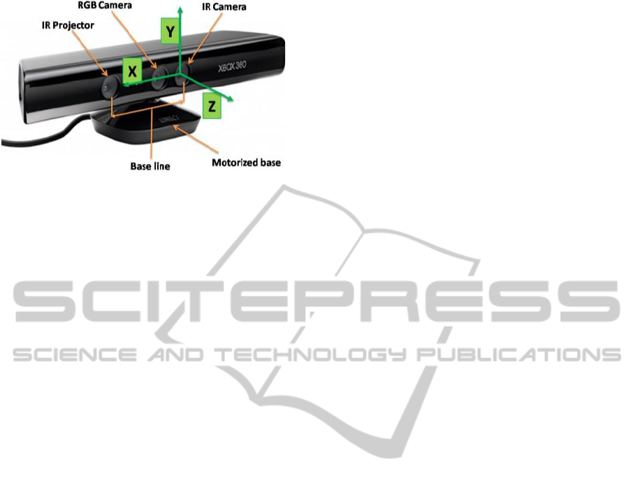
Figure 1: Kinect sensor and coordinate system (taken from
(Garcia and Zalevsky, 2008)).
Although there are some works that use Kinect as an
input sensor for reactive navigation (see for example
(Cunha et al., 2011), (Biswas and Veloso, 2011)), to
the best knowledge of the authors the commented
drawbacks have not been explicitly addressed.
In order to test the suitability of the proposed
approach, a set of experiments has been conducted
within cluttered scenarios. The experiments have
validated the improvement in performance of a
particular reactive navigator (Blanco et al., 2008),
though the solution presented here can be applied to
any other reactive algorithm that utilizes a 2D
representation of the space, i.e. only relying on 2D
laser scanners.
Next section gives a description of the Kinect
device. Section III presents the proposed solution for
the usage of Kinect as an additional input sensor for
any reactive navigation algorithm based on a 2D
obstacle representation. In section IV results from
the conducted experiments are presented and
discussed. Finally, some conclusions are outlined.
2 THE KINECT SENSOR
2.1 Description
The Kinect device (see figure 1) is equipped with an
RGB camera, a depth sensor, a matrix of
microphones, a motorized base which endows the
sensor with a tilt movement of 27º, and a 3-axis
accelerometer.
Focusing on the depth sensor, also called range
camera, it is composed of an infrared light projector
combined with a monochrome CMOS sensor. It has
a VGA resolution (640x480 pixels) with 11-bit
resolution depth, and a data refresh ratio of 30 Hz.
Its nominal field of view is 58º in the horizontal
plane and 45º in the vertical one. The operational
range reported by the manufacturer is from 1.2 m. to
3.5, though in our experiments we have tested that
the sensor is able to detect objects placed at 0.5 m.
(see section 2.3).
2.2 Working Principle of the Range
Camera
The range camera of Kinect consists of two devices:
an infrared (IR) light projector which casts a pattern
of points onto the scene and a standard CMOS
monochrome sensor (IR camera) (Freedman et al.,
2010). Both are aligned along the X axis, with
parallel optical axis separated a distance (baseline)
of 75mm (see figure 1). This configuration eases the
computation of the range image, which is performed
through the triangulation between the IR rays and
their corresponding dot projections onto the image.
The method to compute the correspondence between
rays and pixels relies on innovative technique called
Light Coding (Garcia and Zalevsky, 2008), patented
by PrimeSense (PrimeSense, www.primesense.com),
which entails a very particular factory calibration. In
this calibration, a set of images of the point pattern,
as projected on a planar surface at different known
distances, are stored in the sensor. These are the so-
called reference images.
Kinect works like a correlation-based stereo
system with an ideal configuration (i.e. identical
cameras, aligned axes separated along the X axis)
where the IR rays are “virtually” replaced by line-of-
sight of the points in the reference images. As in
stereo, depth at each image point is derived from its
disparity along the X axis, which is computed by
correlating a small window over the reference
image. Further information about this calculation
can be found in (Khoshelham, 2011).
Regarding the accuracy of this method, the
distance errors are lower than 2 cm. for close objects
(up to 2m.), linearly increasing until an average error
of 10 cm. at 4m.
2.3 Kinect Reliability for Detecting
Thin Obstacles
To assess how much reliable Kinect is to feed a
robot reactive navigation system, it is of interest to
analyze its capacity to detect surrounding obstacles,
particularly those that are hardly detectable by other
sensors, either because of their small size or because
of their position in the scene, e.g. the salient board of
a table, the legs of a chairs, coat stands, etc.
We have performed a number of experiments
where sticks of different thickness (1, 2, and 4 cm.)
were horizontally placed in front of the sensor, at a
ICINCO2013-10thInternationalConferenceonInformaticsinControl,AutomationandRobotics
394
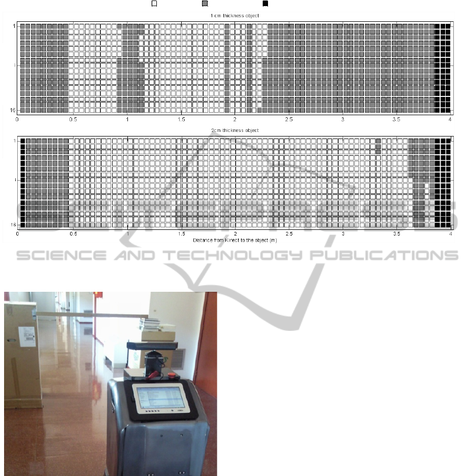
Figure 2: Results for the small obstacle detection experiment. The vertical axis represents the 16 central columns of the
range image. The horizontal axis is the distance, discretized into intervals of 5 cm, from Kinect to the stick horizontally
placed in front of the robot. Each cell encodes whether the stick was detected at any of the image rows considered.
Figure 3: Experiment setup to test the “visual acuity” of
Kinect for detecting small obstacle. In this particular case,
the obstacle is a horizontal stick with a thickness of 4 cm.
certain height, verifying whether they are detected at
different distances. The experiments were conducted
in a corridor with the Kinect sensor mounted on a
mobile robot (see figure 3). To extract the
meaningful data for this analysis we only focused on
a rectangular window of the range image, concretely
the 16 central columns of a small number of
consecutive image rows at the height where the stick
is expected to be. We must account for an interval of
rows since there is no guarantee that the stick is
observed in a single, fixed row during all the robot
run. Notice that, though the stick is roughly
horizontal, its projection on the range image may
cover different rows and also may change from one
position to another.
Starting at a distance of 4 meters from the
obstacle, the robot gradually moves towards it at
discrete increments, while recording range images as
well as the robot odometry at each position. This
experiment was repeated 5 times for each thickness
(1, 2, and 4 cm.).
Figure 2 displays the results of two of these robot
runs, for the 1 and 2cm. stick. It is interesting to see
how the 2cm.-thick stick was almost always
observed over the full operational interval (from 0.5
to 3.5 m.). The plot for the 4cm.-wide stick has been
omitted because it was always detected.
These results reveal the Kinect’s potential for
detecting small obstacles up to an acceptable
distance. Note how in the case of the obstacle of 1
cm its detection is not stable: though it starts to be
detected at 2.3 m, it later disappears because of the
discrete spatial sampling of the sensor.
Object not detectedObject detected
Legend
No measurements available
Central measures
Central measures
Improving2DReactiveNavigatorswithKinect
395
3 KINECT AS INPUT SENSOR
OF A 2D REACTIVE
NAVIGATOR
In general, the use of Kinect to feed a reactive
navigator based on a 2D space representation
presents two difficulties: i) the huge amount of data
it provides, and ii) the existence of a blind zone both
at short distance and because of the narrow
horizontal field-of-view (in comparison to laser
radial scanners). Our solution to overcome these
issues consists of a post-processing stage to
conveniently adapt the data to the specific needs of
the reactive navigator, which may also receive
sensorial information from other sources, e.g. a 2D
laser scanner (see figure 4).
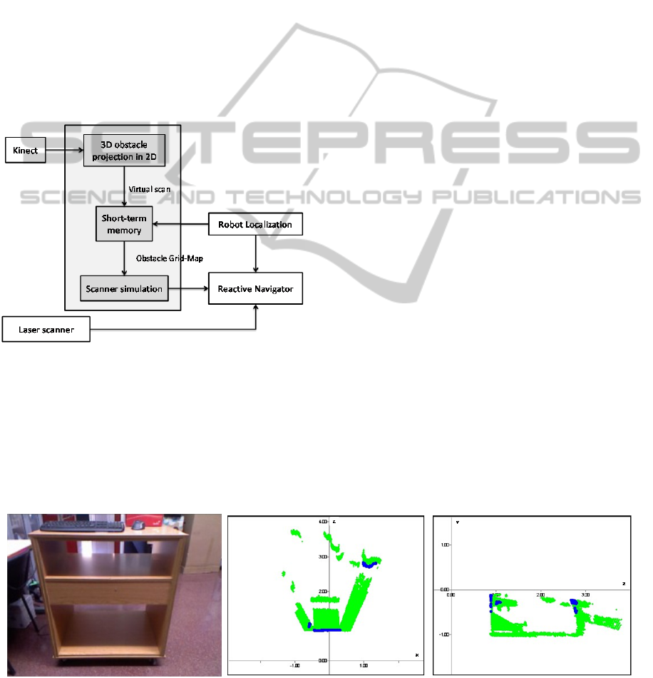
Figure 4: General diagram of the proposed system to
combine data from a laser scanner and a Kinect sensor to
feed a reactive navigator.
The first step of such a post-processing stage aims at
reducing the huge amount of data while keeping the
relevant 3D sensorial information about obstacles. A
second phase strives for coping with the problem of
the blind zone by creating a short-term memory
which temporally recalls the perceived obstacles
around the robot. This memory is then transformed
to a scan format suitable to be exploited by the
reactive navigator. Next, these processes are
described.
3.1 Projection of the Point Cloud to 2D
The Kinect sensor provides more than 300.000
measures per frame at 30Hz. This intense flow of
data provides the robot with very valuable
information about the surrounding but entails two
problems for a reactive navigator: First, it becomes a
significant computational burden that could hamper
the robot to concurrently execute other tasks, e.g.
robot localization, mapping, etc. Second, these data
cannot be directly exploited by conventional robot
reactive algorithms designed to be fed with 2D
scans, such as Virtual Force Field (Borenstein and
Koren, 1989), Nearness diagram (Minguez and
Montano, 2004), PTG-based navigator (Blanco et
al., 2008), etc.
Our approach to overcome these two problems
consists in condensing the 3D Kinect data into a 2D
scan by selecting the minimum measured distance
from each column of the range image. This is a
simple and efficient procedure whose results is a
virtual scan of 640 ranges (the number of columns in
the image) that captures the closest obstacle point
for all the different heights (image rows), as shown
Figure 5.
Please, notice that, by extracting a virtual scan
for different height intervals, this solution could
cope with robots with varying polygonal sections.
The solution implemented in this work, thereby, is a
particular case of this general approach.
3.2 Short Term Memory
A serious limitation of Kinect is its inability to
Figure 5: Left, image of the scene captured by the RGB camera. Middle, top view of the scene perceived by the range
camera. Right, lateral view of the same scene. The green points correspond to discarded measurements, and the blue ones
are those considered for the virtual scan.
ICINCO2013-10thInternationalConferenceonInformaticsinControl,AutomationandRobotics
396
detect close objects, both below its minimum
operational range and out of the field-of-view
(FOV). The minimum range depends on the surface
color and material, and is typically between 0.5 and1
m., while the horizontal and vertical FOV are 58 and
45 degrees, respectively. This blind zone becomes a
serious drawback for a reactive navigator, since
when the robot approaches an obstacle (both with
rotational or translational movements) it suddenly
disappears and the space becomes obstacle-free,
causing the robot to crash into it. To overcome this
problem we propose a short-term memory around
the robot location which maintains previous
measurements temporally. Such a memory has been
implemented through a grid, similarly to an
occupancy map (see figure 6), which is formalized
as follows.
3.2.1 Memory
A short-term memory M is defined as an n x m
matrix, which discretizes a certain bi-dimensional
area around the robot. Let M(i,j) represent the
probability of the cell c
i,j
to be occupied by an
obstacle, based on the observations, o
1
, …, o
k
, of the
robot, that is:
,1
( , ) ( ,..., )
ij k
Mij pc o o
(1)
For the calculation of such a probability it is
convenient to use the so-called log-odds (refer to
(Thrun, 2003) for further detail), which requires the
computation, for each c
i,j
at time t, of the expression:
,1
,
,1
( ,..., )
()log
1 ( ,..., )
ij k
t
ij
ij k
pc o o
lc
pc o o
(2)
The memory cells are initialized with the value:
,
0
,
,
()
()log
1()
ij
ij
ij
pc
lc
pc
(3)
where p(c
i,j
) has been set to 0.5.
Given l
t
it is possible to retrieve the probability
of each cell as:
,
,1
()
1
( ,..., ) 1
t
ij
ij k
lc
pc o o
e
(4)
and from that, we create an obstacle map by
considering that a cell c
i,j
is occupied if its
probability is above a given threshold. To feed the
reactive navigator, a scanner simulator converts this
obstacle grid map into a scan format.
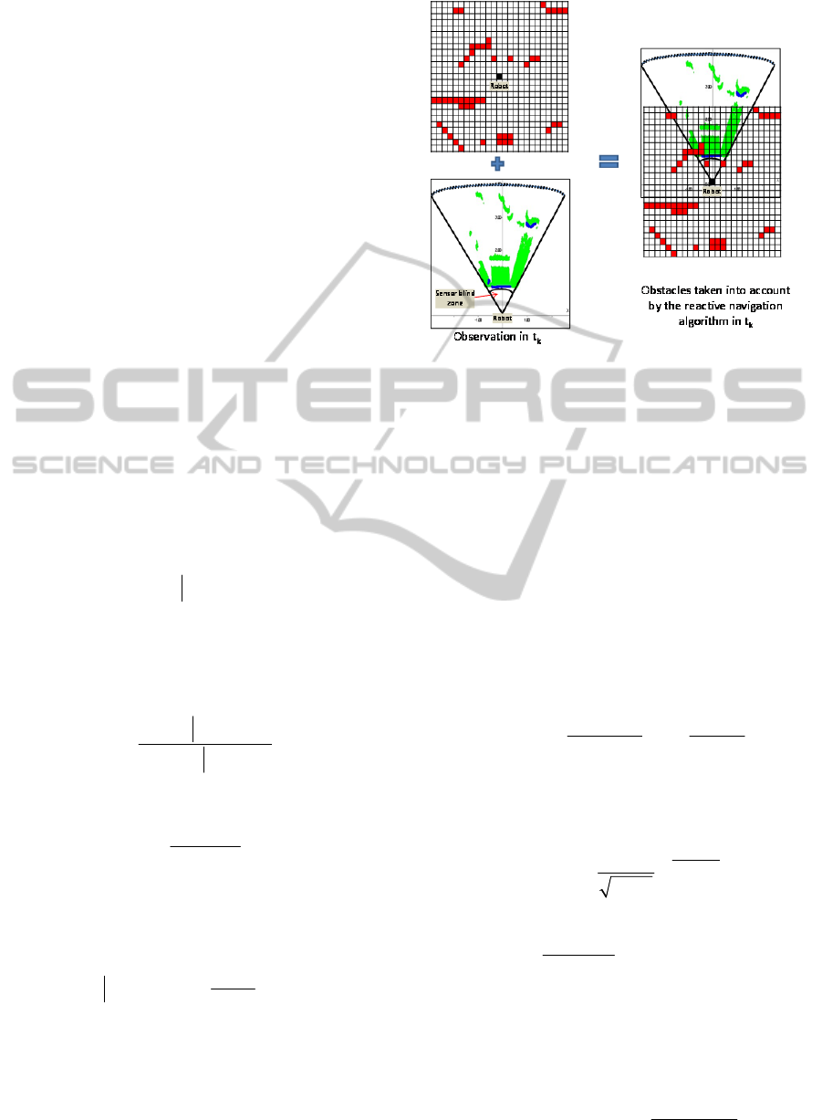
Figure 6: Short-term memory at time t
k
. The memory
stores a set of previous sensor measurements into a grid.
Right, the obstacles considered by the reactive navigator
are formed by the integration of points from the blind zone
(in red) and the current virtual scan (in blue), which is
obtained from the Kinect data (in green).
3.2.2 Memory Update
Let o
t
be a virtual scan observation derived from
Kinect at time t. Let c
k
be the cell where the k-th
measurement of the scan lies, given the current robot
pose. Using the Bayes rule and log-odds, the
updating of the value l
t
(c
i,j
) as a consequence of a
new scan o
t
is performed through the following
expression (see (Thrun, 2003)):
,,
1
,,
,,
,
(|) 1()
() ()log log
1(|) ()
ij k
ij t ij
tt
ij ij
ij t ij
cc
pc o pc
lc l c
pc o pc
(5)
where the a posteriori probability
,
(|)
ij t
pc o
is
calculated with the Bayes rule using the following
sensor model:
2
,
2
()
,
2
1
(| , 1)
2
tij
od
tij
po M c e
(6)
where d
i,,j
is the distance to the center of the cell c
i,j
.
The term
,
,
1()
log
()
ij
ij
pc
pc
is a constant which
depends on the selected value of the a priori
probability
,
()
ij
pc
. Therefore, considering
,
()0.5
ij
pc
, the calculation of the memory update
is simplified to:
,
1
,,
,
(|)
,( ) ( ) log
1(|)
ij t
tt
ij k i j i j
ij t
pc o
cclc lc
pc o
(7)
Improving2DReactiveNavigatorswithKinect
397
Notice that, according to this update mechanism a
cell requires persistent observations to change from
occupied to free, and viceversa. Also, note that non-
observed cells are not updated, i.e., they keep their
values.
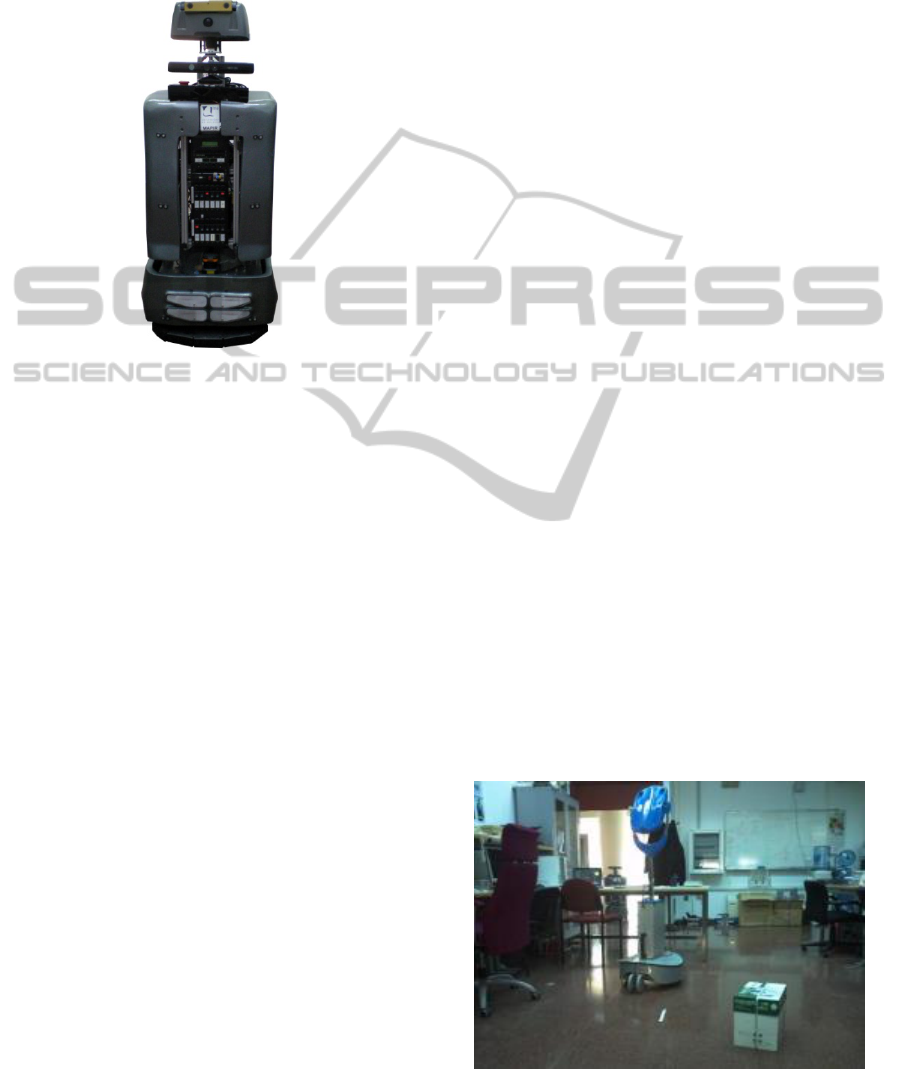
Figure 7: Mobile robot SANCHO, equipped with 2
Hokuyo laser scanners and a Kinect sensor for obstacle
avoidance.
4 IMPLEMENTATION
AND DISCUSSION
The proposed approach has been implemented in the
mobile robot SANCHO (Gonzalez et al, 2009) (see
figure 7. The size of the short-term memory was set
to 100 x 100 cells, for a 2 x 2m. area around the
robot, i.e., with a cell size of 2 cm.
SANCHO, built upon a commercial Pioneer
3DX base, is equipped with two Hokuyo laser
scanners (Hokuyo, www.hokuyo-aut.jp) placed at 30
cm. over the floor (scanning the front and the rear
of the robot) and a Kinect sensor in its front upper
part (see figure 7).
The reactive navigation system of SANCHO,
called PTG-based navigator, transforms the 2D local
obstacles in the 3D Configuration Space of the robot
into the so-called “Trajectory Parameter Spaces”
(TP-Spaces). A TP-Space is a 2D representation of
all the poses the robot could reach if it moved
according to a certain path model. Since several path
models are considered by the reactive system,
several TP-Spaces are built. The mathematical
transformation between the C-Space and the TP-
Spaces is done by “Parameterized Trajectory
Generators” or PTGs, each one representing a path
model (e.g. circular, turn&move-straight, etc.) that
fulfills certain geometrical and topological
properties. As a result of this transformation the
robot in the TP-space becomes a free-flying point
whose motion might be solved by any holonomic
obstacle avoidance, such as Virtual Force Field
(Borenstein and Koren, 1989) or Nearess Histogram
(Minguez and Montano, 2004). Please, refer to
(Blanco et al., 2008) for a more detailed explanation
of the PTG-based navigator. An interested feature of
the PTG-based navigator is that it can deal with
several sensors that provide surrounding information
simultaneously.
When using only the two radial laser scanners,
SANCHO is prone to crash with many unobserved
objects that it may encounter in a typical
environment, e.g. tables, chairs, boxes, plants, coat
stands, shelves, etc. After incorporated the Kinect
sensor this problem has been drastically reduced,
though not completely eliminated. Since a precise
quantification of the improvement level of the
proposed approach is not possible we have tried to
validate the method with two different tests. In the
first, we have repeated a number of robot local
navigations, i.e. go from A to B, with the two
sensing configurations (wiht and without Kinect)
and varying the obstacles along the path. Figure 8
shows one of these setups in our lab, with obstacles
at different heights, including a papers box, the base
of another robot, the board of a table, and a coat
stand with jackets. Some of the trajectories followed
by the robot are shown in figure 9. The red one
corresponds to the navigation performed using only
the radial laser scanners, which ends up with the
robot bumping into the cardboard box. On the
contrary, when using Kinect (the other three paths),
SANCHO manages to negotiate all the obstacles, so
reaching the goal successfully.
A second experiment has consisted of robot
SANCHO moving randomly for more than 20 hours
Figure 8: Scenario where some of the experiments were
conducted.
ICINCO2013-10thInternationalConferenceonInformaticsinControl,AutomationandRobotics
398
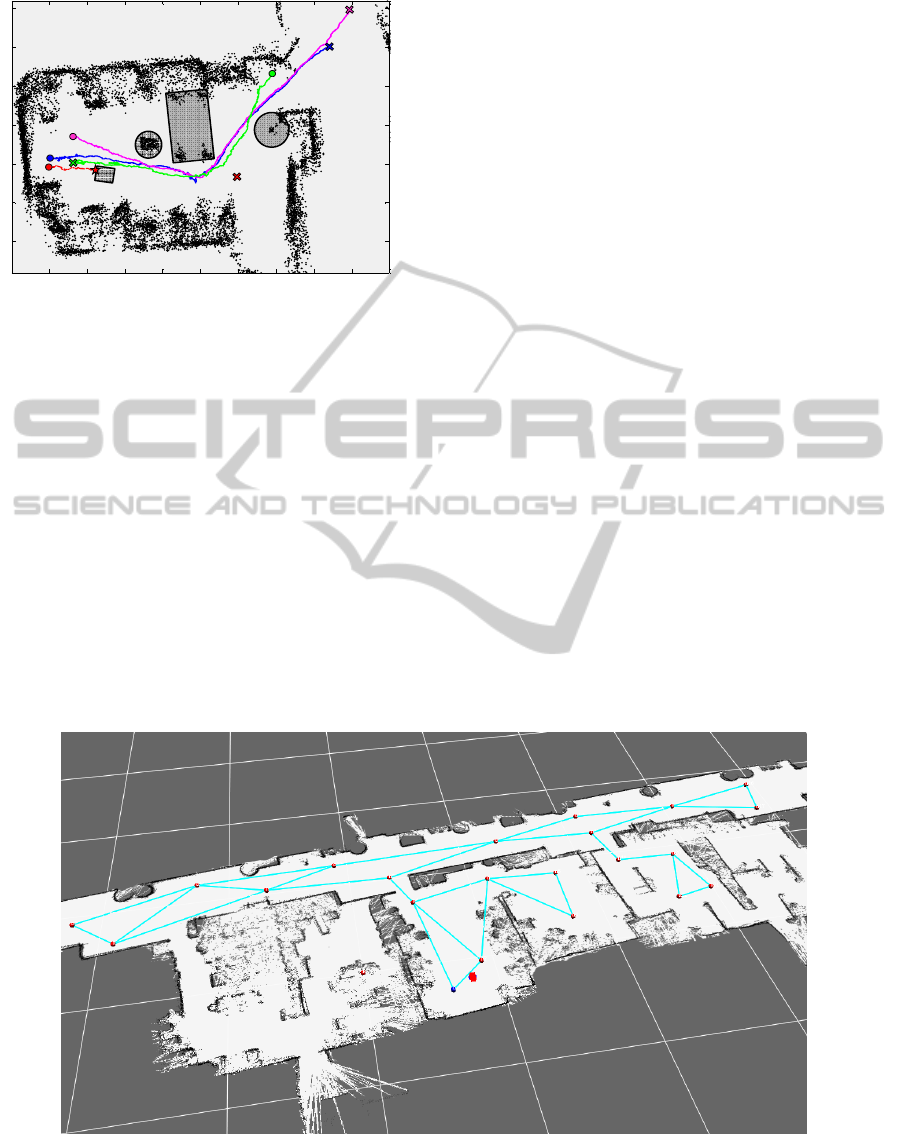
Figure 9: Paths followed by the robot during four different
navigations. The colored circles represent the initial
position of the robot, and the crosses correspond to the
target locations. Black points are obstacles detected by the
laser range finders. The rectangles and circles have been
added manually, and represent the obstacles undetected by
the laser scanners. Axis units are meters.
A second experiment has consisted of robot
SANCHO moving randomly for more than 20 hours
(in sessions of around 2 hours) in the environment
represented in the map of Figure 10. The reactive
navigation in this case was running as the lower part
of a hybrid navigational system with a topological
navigation on top (Fernández-Madrigal et al., 2004).
During all these sessions SANCHO suffered 5
collisions: three when passing doorways and 2 when
making rapid turns.
5 CONCLUSIONS
In this paper we have presented methods to
conveniently adapt the 3D information provided by a
Kinect device to work with a reactive navigator
designed to cope with radial laser scanners. It has
been proposed solutions for two of the major Kinect
drawbacks: the huge amount of data provided by the
sensor, more than 300.000 measures per frame at
30Hz, and its large blind zone due to both its narrow
field-of-view and the lower limit of its operational
range (from 0.5 to 1m., depending on the surface
characteristics).
We have experimentally demonstrated the Kinect
potential to detect small obstacles, a key aspect for
safety during a reactive navigation. Finally, a
number of tests have been conducted, validating the
suitability of the proposed methods.
ACKNOWLEDGEMENTS
This work has been supported by two projects:
“GiraffPlus”, funded by EU under contract FP7 -
ICT - #288173, and “TAROTH: New developments
toward a robot at home”, funded by the Spanish
Government and the “European Regional
Development Fund ERDF” under contract DPI2011-
25483.
Figure 10: Topological and metric maps used in the second experiment mapping 6 rooms connected by a large corridor. Red
nodes represent topological locations and blue lines the possible paths between them. Orders to the robot were to navigate
randomly between nodes during periods of 2 hours. The metric map was used for localization purposes.
-2 -1 0 1 2 3 4 5 6 7 8
-
2
-
1
0
1
2
3
4
Improving2DReactiveNavigatorswithKinect
399

REFERENCES
Biswas, J., Veloso, M., 2011. Depth Camera based
Localization and Navigation for Indoor Mobile
Robots. In RGB-D Workshop at RSS 2011.
Blanco, J. L., Gonzalez, J., Fernandez-Madrigal, J.A.,
2008. Extending Obstacle Avoidance Methods
through Multiple Parameter-Space Transformations.
In Autonomous Robots, vol. 24 (1).
Borenstein, J., Koren, Y., 1989. Real-time Obstacle
Avoidance for Fast Mobile Robots. In IEEE
Transactions on Systems, Man, and Cybernetics, vol.
19, no. 5.
Cunha, J., Pedrosa, E., Cruz, C., Neves, A., Lau, N., 2011.
Using a Depth Camera for Indoor Robot Localization
and Navigation. In RGB-D Workshop at RSS 2011.
Fernández-Madrigal, J. A., Galindo, C., González, J.,
2004. Assistive navigation of a robotic wheelchair
using a multihierarchical model of the environment. In
Integrated Computer-Aided Engineering vol.11, no. 4.
Fiorini, P., Shiller, Z., 1988. Motion Planning in Dynamic
Environments using Velocity Obstacles. In The
International Journal of Robotics Research, vol. 17,
no. 7.
Freedman, B., Shpunt, A., Machline, M., Arieli, Y., 2010.
Depth Mapping using Projected Patterns. Patent No.:
US 2010/0118123 A1.
Garcia, J., Zalevsky, Z., 2008. Range Mapping Using
Speckle Decorrelation. Patent No.: US 7,433,024 B2.
Gonzalez, J., Galindo, C., Blanco, J.L., Fernandez-
Madrigal, J.A., Arevalo, V., Moreno, F.A., 2009.
SANCHO, a Fair Host Robot. A Description. In IEEE
International Conference on Mechatronics (ICM),
Malaga, Spain.
Holz, D., Lörken, C., Surmann H., 2008. Continuous 3D
Sensing for Navigation and SLAM in Cluttered and
Dynamic Environments. In International Conference
on Information Fusion of the (FUSION). Cologne,
Germany.
Hokuyo: http://www.hokuyo-aut.jp/
Kinect: http://www.xbox.com/en-US/kinect.
Khoshelham, K., 2011. Accuracy analysis of kinect depth
data. In ISPRS Workshop Laser Scanning, Calgary,
Canada.
Marder-Eppstein, E., Berger, E., Foote, T., Gerkey, B.,
Konolige, K., 2010. The Office Marathon: Robust
navigation in an indoor office environment. In IEEE
International Conference on Robotics and Automation
(ICRA).
Minguez, J., Montano, L., 2004. Nearness Diagram (ND)
Navigation: Collision Avoidance in Troublesome
Scenarios. In IEEE Transactions on Robotics and
Automation, vol.20, no.1.
PrimeSense: http://www.primesense.com.
Thrun, S., 2003. Learning occupancy Grid Maps with
Forward Sensor models. Autonomous Robots, n. 15.
ICINCO2013-10thInternationalConferenceonInformaticsinControl,AutomationandRobotics
400
