
Intelligent Control of a Prosthetic Ankle Joint
Anh Mai and Sesh Commuri
School of Electrical and Computer Engineering, University of Oklahoma, Norman, Oklahoma, U.S.A.
Keywords: Intelligent Control, Prosthetic Foot, Optimization.
Abstract: The ability to control the prosthetic ankle joints of below-knee amputees is a challenging problem due to the
lack of adequate mathematical models, the variations in the gait in response to the environment, sensor
noise, and unknown intent of users. Artificial ankle joints are required to exhibit variable stiffness based on
the gait and aid in locomotion as well as stability of the individual. It is desirable for control strategies for
such ankle joints to adapt in real-time to any variations in the gait, have robust performance, and optimize
specified performance indices relating to efficiency of the gait. In this paper, we investigate the potential of
Direct Neural Dynamic Programming (DNDP) method for learning the gait in real-time and in generating
control torque for the ankle joint. The residual limb is first represented by a link-segment model and the
kinematic patterns for the model are derived from human gait data. Then augmented training rules are
proposed to implement the DNDP-based control to generate torque which drives the prosthetic ankle joint
along the designed kinematic patterns. Numerical results show that the DNDP controller is able to maintain
stable gait with robust tracking and reduced performance cost in spite of measurement/actuator noises and
variations in walking speed.
1 INTRODUCTION
Current ankle/foot prostheses are primarily passive
devices whose performance cannot be adapted or
optimized to meet the requirements of different
users. Further, such devices cannot provide the
rigidity, as well as the flexibility and power similar
to that of a human foot. The adverse consequences
of wearing less functioning prosthetic feet include
asymmetric gait, increased metabolic consumption,
limited blood flow, instability, and pain. In the long-
term, the amputees, especially ones with diabetes,
might have to undergo hip replacement procedure
and use wheel-chair on a daily basis.
The lack of an active prosthetic joint that can
dynamically adapt to changing terrain and gait needs
is a limiting factor in attaining adequate comfort and
mobility in below-knee amputees. Powered ankle
prostheses can adapt to some extent, but the rigidity
and power required during the gait are usually
varying depending on the activity pursued by the
individual. Such unknown, varying requirement
cannot be addressed through standard control
techniques. One of the key steps in the development
of these active prosthetic feet is the generation of
adaptive torque profiles to drive the ankle joint in
response to variations in the human locomotion. The
design should also provide necessary energy return
to significantly reduce the metabolic energy
consumption during locomotion (Versluys et al.,
2009). In an effort to achieve these goals, bionic feet
such as Proprio Foot (Össur), BiOM (iWalk, 2012),
SPARKy (Hitt et al., 2009), PPAMs (Versluys et al.,
2008) have been equipped with active components
that can modify the dynamic characteristics of the
prosthetic ankle joints. It is noted that the ankle
joints currently available are typically controlled
using classical control techniques. Once the
controller is tuned, its parameters are usually fixed
irrespective of any changes in gait. Adaptive control
strategies can account for changes in gait. However,
such adaptive strategies have to overcome the
challenges due to lack of information on gait and
interaction between the foot and the ground as well
as the interaction between the prosthetic socket and
the residual limb. In the absence of such
information, optimization of the performance of the
controller becomes a very challenging task and
requires the use of new design strategies such as
learning-based control.
Mathematical models and experimental data can
be effectively combined to generate forward
17
Mai A. and Commuri S..
Intelligent Control of a Prosthetic Ankle Joint.
DOI: 10.5220/0004485600170025
In Proceedings of the 10th International Conference on Informatics in Control, Automation and Robotics (ICINCO-2013), pages 17-25
ISBN: 978-989-8565-70-9
Copyright
c
2013 SCITEPRESS (Science and Technology Publications, Lda.)

simulation of both normal and pathological gaits
(Millard et al., 2008; Peasgood et al., 2007; Thelen
and Anderson, 2006).
Figure 1 shows the diagram of the control-based
approach which concentrates on generating suitable
control signals to drive the model dynamics along
desired trajectories obtained from the analysis of
human gait (Xiang et al., 2010). In this framework,
different methods of generating the joint torque can
be analytically evaluated and the overall
performance can be improved by feedback
modification. Similarly, simulation frameworks
which combine mathematical gait model and
experimental data can be used to study the effect of
prosthesis on kinematic behaviours and other aspects
of amputee locomotion (Pejhan et al., 2008; Brugger
and Schemiedmayer, 2003). Such simulation enables
a quick evaluation of the performance of the
prosthetic device under different operating
conditions and extend the understanding of the
prosthetic ankle-foot systems (Hansen, 2005).
However, due to the complex interaction between
the gait and the ground and the unknown intent of
the user, it is not easy to guarantee efficient gait or
robustness in performance. Therefore, a suitable
control strategy that permits online adaptation to
variations in gait while guaranteeing robust
performance and improved efficiency has to be
developed.
Figure 1: Control-based approach to the modelling and
control of human gait.
In this paper, the use of Direct Neural Dynamic
Programming-based control (Si and Wang, 2001) of
an active prosthetic ankle joint is evaluated. DNDP
has been shown to be suitable for control of complex
nonlinear systems with unknown dynamics and
disturbances (Lu et al., 2008; Enns and Si, 2003).
Furthermore, this approach also tries to minimize the
long-term cost function in the sense of Bellman‘s
principle of optimality (dynamic programming).
With these properties, DNDP appears to be a good
candidate for a challenging task such as control of a
prosthetic ankle. In order to apply this control
technique, this paper addresses issues such as gait
dynamics formulation, desired behaviours of the
ankle joint during gait, control strategies, and long-
term gait-related performance indices. In addition,
augmented training rules are proposed to provide
robustness against the foot-ground interaction
disturbance. This is the first attempt in applying such
a real-time adaptation scheme in learning the gait
parameters and adjusting the control output to
improve the gait and eliminate the asymmetry in gait
between the amputated and the intact sides of the
individual while enabling the individual to have a
more active lifestyle. This will have enormous
impact on the quality of life as well as the long-term
health of people with below-knee amputation.
The rest of this paper is organized as follows.
Section 2 describes the system models which include
the dynamics of the gait and ground-foot interaction.
Section 3 and 4 gives detailed information on
kinematic pattern generation and control structures,
respectively. Simulation setup with result
discussions are presented in Section 5 and the
conclusions of the investigation are presented in
Section 6.
2 DYNAMICAL MODELS
2.1 Gait Model
The dynamic model in the sagittal plane of the
residual limb of a unilateral below-knee amputee is
considered in this study. This link-segment model
includes 3 revolute joints: the hip joint connecting
the biological thigh with the upper part of the human
body; the knee joint connecting the biological thigh
with the residual limb/artificial shank, and the
prosthetic ankle joint connecting the artificial shank
with the prosthetic foot. The action of the human
muscles and ligaments that control the hip and knee
joints are represented by the torques at those
biological joints. At the prosthetic ankle joint, an
externally powered actuator generates a torque to
manipulate the angular position of the ankle.
ICINCO2013-10thInternationalConferenceonInformaticsinControl,AutomationandRobotics
18

The kinematic and dynamic relationship of the link-
segment model in Figure
2 is obtained using the
Euler-Lagrange formulation (Amirouche, 1992)
following assumptions similar to those in Section
5.0.1 and Section 8.0.1 of (Winter, 2009). The
interaction between the residual limb and the socket
to which the prosthetic foot is connected is ignored
and the residual-biological-artificial shank is
considered rigid. The equations that govern the
dynamics of the overall human-prosthetic system
can be expressed as follows:
,
H
GRF
M
VGFaDF
(1)
where
123
T
are joint angles (rad),
123
T
are joint angular velocities
(rad/s), and
123
T
are joint angular
accelerations (rad/s
2
);
T
HHH
axy
are the hip
acceleration (m/s
2
),
123
T
are
components of joint torques (Nm), and
Figure 2: Link-segment representation of the residual limb
with a prosthetic ankle joint.
T
GRF X Z
F
FF
are horizontal and vertical
components of the ground reaction force (N). The
nonlinear terms in (1) include the inertia matrix
M
, the Coriolis and Centripetal term
,V
,
the gravity term
G
, the coefficient matrix
F
representing the translation of the hip, and the
coefficient matrix
.
D
that represents the effect of
the ground reaction force on the dynamic of each
joint. Among these components, the ground reaction
forces play a very important role and will be
described in the subsequent section.
2.2 Ground Reaction Force
According to Winter (Winter, 2009), there are three
forces acting on the link-segment model of the
human gait: gravitational force, ground reaction
force, and muscle and ligament forces. In the
depicted gait model, the gravitational force is
represented by the nonlinear term
G
whereas the
force generated by the muscles and ligaments are
replaced by the torque applied at the biological hip
and knee joints. The ground reaction forces are
generated during the gait as the result of interaction
between the foot and the ground. Such reaction
forces are then transferred up to the ankle, knee, and
hip joints with the effect of altering the joint angular
positions. Because the interaction between the foot
and the ground is very complicated, it is very hard, if
not impossible to exactly measure the ground
reaction force without using carefully designed gait
lab and force transducers (Winter, 2009). On the
other hand, the ground reaction force (GRF) cannot
be ignored during the simulation of the human gait
(Wojtyra, 2003; Peasgood et al., 2007). Therefore,
the following widely used model is selected to
represent the ground reaction force for the
experimental simulations used in this study
(Peasgood et al., 2007; Millard et al., 2008).
max max
,0,0, ,
e
Z
PEN PEN
F
kz Stepy d c z
(2)
sgn
XZ COP
FF x
(3)
In this GRF model,
Z
F
and
X
F
are vertical and
horizontal force components (N);
,
P
EN PEN
zz
are the
penetration (m) and penetration rate (m/s);
,ke
are
spring coefficient (N/m) and spring exponent;
max
c is
the maximal damping coefficient (N/(m/s));
max
d is
the maximal damping penetration (mm);
is the
friction coefficient; and
COP
x
is the horizontal
velocity of the contact point with respect to the
ground (m/s). Detailed descriptions of the parameters
of this model can be found in (Peasgood et al., 2007).
The use of this ground reaction force model is
more realistic than the rigid contact approach
because it can simulate the viscous-elastic behaviour
of the foot-ground interaction (Bruneau and
IntelligentControlofaProstheticAnkleJoint
19
Ouezdou, 1997). The penetration of the foot into the
ground is modified from (Marhefka and Orin, 1999).
Because the ground reaction force can neither be
measured exactly nor be ignored, the ground
reaction force is treated as external disturbance to
the gait dynamics during the simulation of the
control strategy.
3 KINEMATIC PATTERN
GENERATION
In order to study the effectiveness of the DNDP-
based control strategy, the behaviour of the overall
human-prosthetic system under different gait
conditions has to be investigated. The different gaits
are represented by kinematic patterns of angular
positions, velocities, and accelerations of each of the
joints. These quantities are obtained from the gait
lab database (Winter, 1991) from real human
subjects and are widely used in simulation of human
gait. From the gait lab database, the analytical forms
of the desired joint trajectories in time domain are
generated to allow multi-step simulation of the
model (Millard et al., 2008).
The desired joint trajectories of the hip, knee,
and ankle joints, and the vertical Cartesian trajectory
of the hip joint are approximated by five-term
Fourier series as in equation below. The horizontal
Cartesian trajectory of the hip joint is approximated
by the sum of a first order polynomial (linear) and
five-term Fourier series as in equation below. Given
these analytical form trajectories, the required first
and second order derivatives can be calculated
without introducing any discontinuities in the model
during simulation.
4 CONTROL STRUCTURE
Figure 3 shows the structure of the controller used in
this study. The control structure can be divided into
the control for the biological joints (hip and knee
joints), and control for the prosthetic ankle joint.
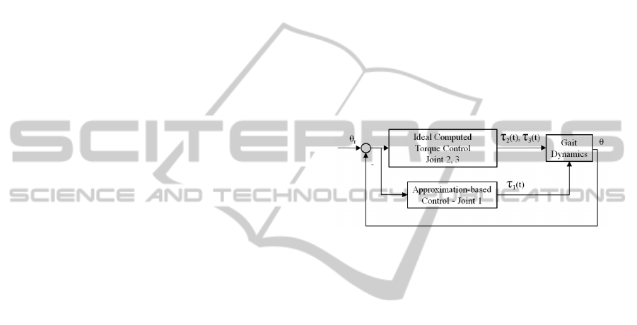
4.1 Control of the Hip and Knee Joints
For the biological hip and knee joints, it is assumed
that below-knee amputees are able to adjust their
muscle activities to generate enough torques to
manipulate these joints and maintain normal gait
despite possible control efforts at the prosthetic
ankle joint. For that reason, ideal computed torque
control is applied at the hip and knee joints. These
ideal torques are computed assuming that the (noisy)
joint angles, angular velocities, and angular
accelerations, as well as the nonlinear terms in (1)
are known. Such control inputs have the same
structure as the ideal computed torque control for
robot manipulators (Lewis et al., 1999).
Equations (8) and (9) describe the ideal
computed torque control applied at the biological hip
and knee joints during simulation of the model, in
which
iiri
e
and
iiri
e
are tracking
errors of each joint,
ir
is a desired angular
acceleration of each joint,
0, 0
Di Pi
KKare
design parameters.
Figure 3: Control structure with ideal computed torque
control at hip and knee joints, and approximation-based
control at the prosthetic ankle joint.
4.2 Control of the Ankle Joint
The angular position of the prosthetic ankle joint can
be controlled by an external actuator. In this model,
the dynamics of the actuator are ignored and only
the torque produced at the prosthetic joint is
considered. In contrast to the ideal joint controllers
used for the biological hip and knee joints, the
actuator at the prosthetic ankle joint is assumed to
have access to only the actual ankle angle and
angular velocity. Such quantities could be measured
by using a rotational encoder and gyroscope
mounted on the prosthetic foot. Therefore, the torque
produced by an external actuator could be a function
of the ankle angle, the ankle angular velocity, and
the tracking error between these quantities and their
desired kinematic patterns as follows:
1 1111
,,,
f
ee
(4)
where
11
andee
are tracking errors of the ankle angle
and ankle angular velocities as defined above.
The filtered tracking error is used as in (Lewis et
al., 1999):
1111
re e
(5)
ICINCO2013-10thInternationalConferenceonInformaticsinControl,AutomationandRobotics
20

5
321 0
1
,,, cos sin
rrrHr i i
k
t t t z t a a kwt b kwt
(6)
5
000
1
cos sin
Hr i i
k
x
tktmc c kwtd kwt
(7)
2 21 1 11 11 22 2 22 22 23 3 33 33
21 1 22 2 23 3 2 21 22 21 22
rD P rD P rD P
HH X Z
M
Ke Ke M K e Ke M Ke Ke
VV V GFxFzDFDF
(8)
3 31 1 11 11 32 2 22 22 33 3 33 33
31 1 32 2 33 3 3 31 32 31 32
rD P rD P rD P
HH X Z
M
Ke Ke M K e Ke M Ke Ke
VV V GFxFzDFDF
(9)
in which
1
0
is the design parameter.
With the introduction of the filtered tracking
error, the dynamics of the ankle joint
11 1 12 2 13 3 11 1 12 2 13 3
1 11 12 1 11 12HH X Z
MM MVVV
GFx Fz DF DF
(10)
can be written in term of the filtered tracking error
as follows:
11 1 11 1 1 1
Mr Vr f x
(11)
with the nonlinear term
1
f
x
is given as:
111111122222
13 3 3 3 3 11 1 1 1
12 2 2 2 2 13 3 3 3 3
111 12 11 12
rr
rr
rr
HH X Z
fx M e M r e
MreV e
VreVre
GFx Fz DF DF
(12
)
This nonlinear term, especially the contribution of
the acceleration of the hip joint (
11 12
H
H
F
xFz
) and
the moments generated by the ground reaction force
(
11 12
X
Z
DF DF), is unknown and difficult to
compute. The nonlinearity of this function is further
increased in multi-step simulation due to the fact
that the ground reaction forces only affect the gait
dynamics during the stance phases when the residual
limb is contacting the ground. However, these forces
are not present during the swing duration. To
overcome these difficulties, this nonlinear function
will be approximated in the DNDP-based
framework.
Given the approximation of the nonlinear term
1
f
x
, the approximation-based control signal will
be selected as follows:
11 11
ˆ
V
f
xKr
(13)
with
1
ˆ
f
x
is an approximation of
1
f
x
and
11V
K
r is
a Proportional-Derivative (PD) control term, and
1
r
is the filtered tracking error in (5).
4.2.1 DNDP-based Control Structure
The DNDP-based control structure comprises of two
neural networks: critic network and action network.
The critic network is responsible to generate an
approximate of the long-term cost function which
satisfies the Bellman’s principle of optimality. The
action network is responsible for generating a
control signal which leads to the optimization of the
approximated long-term cost (or output of the critic
network). Figure 4 presents the two-network
configuration of the DNDP-based control. The next
section will provide detailed information about
elements in Figure 4.
Figure 4: DNDP-based control of the prosthetic ankle
joint.
4.2.2 Detailed Implementation
The critic network approximates the discounted
long-term cost which is represented as the weighted
sum of the short-term (instantaneous) cost as
follows:
IntelligentControlofaProstheticAnkleJoint
21

2
12 3
11
Lt St St St
St Lt
(14)
with
is the discount factor.
Because the critic network is responsible for
calculation of the quantity
Jt
as an approximation
of the long-term cost function
Lt
, the
backpropagation error is defined as:
1
C
CURRENT
TARGET
OUTCOME
et Jt St Jt
(15)
where
St
is the instantaneous cost at time
t
(short
term cost).
Inputs to the critic network are:
1111 1
ˆ
T
CA
xee fx
(16)
and the critic network output is the approximation of
the long-term cost function defined in equation (14):
11
ˆˆ
ˆ
ˆˆ
ˆ
1, , ,1
CC
TT
CC CC
LN
TT
CCCC
ij
JW Vx
Wi Vijxj
(17)
with
C
L is the number of nodes in the hidden layer,
and
5
C
N is the number of inputs to the critic
network.
Weights of the critic network are trained as
follows:
2
ˆˆ
ˆ
CCCCCCCC
WFe kFeW
(18)
2
ˆˆ ˆ
ˆ
T
CCCCCCCCCC
VGexW kGeV
(19)
in which
is the discount factor, ,,
CCC
F
Gkare
design parameters, and
ˆ
C
is the Jacobian matrix
defined as:
ˆ
ˆ
ˆ
ˆ
T
CCC
C
T
CC
Vx
Vx
In this design, the action network approximates
the unknown nonlinear function
1
f
x
. In general,
the action network is responsible for generating a
control which results in the optimization of the long-
term cost function, i.e. the output of the critic
network. Therefore, the backpropagation error of the
action network is given as follows:
AC
CURRENT
TARGET
OUTCOME
et U t Jt
(20)
where
C
Ut
is an ultimate control goal, or the
target for the long-term cost approximate
J
t
.
Inputs to the action network are:
1111
T
A
xee
(21)
and structure of the action network is as follows:
1
11
ˆ
ˆˆ
ˆ
ˆˆ
ˆ
1, , ,1
AA
TT
AA AA
LN
TT
AAAA
ij
fW Vx
Wi Vijxj
(22)
in which
A
L is the number of nodes in the hidden
layer, and
4
A
N
is the number of inputs to the
action network.
Weights of the action network are trained as
follows:
1
2
ˆˆˆˆ
ˆˆ ˆ
ˆ
T
AAAACACCAAAA
AA A A
WFeV WFVxr
kF e W
(23)
2
ˆˆˆˆ ˆ
ˆˆ
T
AAAACACCAAAAAA
VGexV WW kGeV
(24)
in which
ˆ
CA
V
is obtained from
ˆ
C
V to map from
1
ˆ
A
f
x
to the hidden node output, ,,
A
AA
F
Gkare
design parameters, and
ˆ
A
is the Jacobian matrix
defined as:
ˆ
ˆ
ˆ
ˆ
T
A
AA
A
T
AA
Vx
Vx
Compared to the weight updating rules in (Si and
Wang, 2001), it is noted that the last terms in (18),
(19), (23), and (24) provide robustness against the
disturbances generated by the ground reaction forces
which affect the gait dynamics during stance phase of
the gait cycle. Finally, the DNDP-based control is
given as in (13).
4.2.3 Selection of the Short-term
(Instantaneous) Performance Index
(Cost) and the Ultimate Control Goal
The short-term (or instantaneous) cost at each time
step is calculated as follows:
ICINCO2013-10thInternationalConferenceonInformaticsinControl,AutomationandRobotics
22
2
2
11 11
11
11
22
rr
MM
tt tt
St
(25)
where
11
,tt
,
11
,
rr
tt
and
11
,
MM
are actual, desired, and maximal values of the ankle
joint angular position and velocity. This selection
relates to the gait efficiency in the way that if the
prosthetic ankle joint can perform as closed as
possible to the biological ankle, then the hip and
knee joints will not have to modify their behaviours.
As the result, the overall human-prosthetic system
can provide normal gait.
The ultimate control goal is selected as
0
C
Ut
which implies the maximization of the
long-term cost function which is the weighted sum
of the short-term cost.
5 NUMERICAL STUDY
In this section, the performance of the DNDP-based
control is evaluated through simulation of the
developed link-segment model with the presence of
measurement/actuator noises and variations in
walking speed.
5.1 Simulation Setup
Kinematic data collected from human subjects
during walking with different cadences (natural, fast,
slow) in the gait lab (Winter, 1991) is converted to
represent the kinematic patterns for the human-
prosthetic dynamic model in corresponding gaits
with normal, fast, and slow walking speed. For
multi-step simulation of the gait dynamic (1), the
kinematic patterns are approximated by using
equations (6) and (7).
Design parameters for the ideal computed torque
controls at the hip and knee joints are
10
P
K
and
5
D
K . At the ankle joint, the DNDP-based
control is generated by an action network with 4
nodes at the input layer, 8 nodes in the hidden layer,
and 1 node in the output layer. The critic network
has 5 nodes at the input layer, 10 nodes at the hidden
layer, and 1 node at the output layer. Both networks
use sigmoid activation functions and are fully
connected with randomly initialized weights in the
range
1,1
. Other design parameters include the
discount factor
.95
and PD control with
1
5
V
K
and
1
10
. The unknown nonlinear function
1
f
x
is approximated by (22). The critic network
and action network weights are updated using (18)-
(19) and (23)-(24), respectively. Equation (25) is
used to calculate the short-term cost at each time
step.
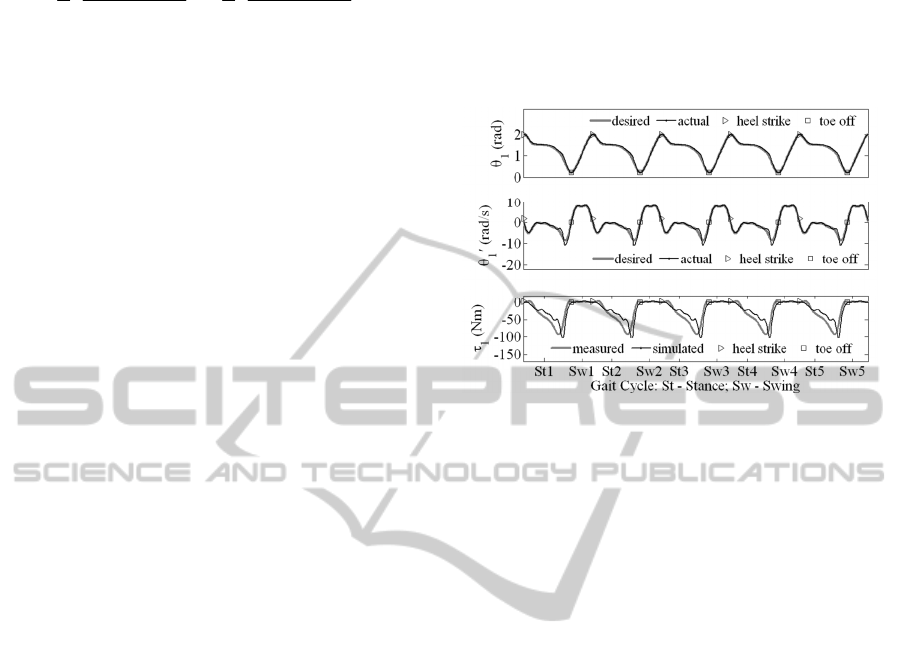
Figure 5: Tracking performance of the DNDP-based
control during normal speed under ideal conditions.
5.2 Ideal Condition
In this ideal condition, the model is simulated during
a gait including 20 steps of normal speed without
any measurement and actuator noises. The tracking
performance of the ankle joint and DNDP-based
torque action for 5 steps are shown in Figure 5. It is
observed that both the ankle position and angular
velocity can follow their desired trajectories with
small errors. More interestingly, the DNDP-based
ankle torque generated during simulation of the
model is very similar to the biological ankle torque
measured from human subjects during gait lab
testing (Winter, 1991).
5.3 Effect of Measurement
and Actuator Noises
Uniformly distributed measurement noises are added
to the ankle position and angular velocity. Torque
output generated for the ankle joint is also added
with uniformly distributed actuator noise as follows:
1
1
1
11 1
11 1
11 1
(26)
where
1
,
1
, and
1
are in the range
2% ,2%
(or
5% ,5%
). The model is simulated with 20
IntelligentControlofaProstheticAnkleJoint
23

steps of normal walking speed and increasing
measurement and/or actuator noises (see
Table 1).
Table 1: Long-term cost during 20 steps of normal
walking speed and increasing measurement/actuator
noises.
Noise PD FLNN DNDP
2% measurement noise 0.715 0.239 0.075
5% measurement noise 3.96 2.003 0.118
5% measurement noise
and 2% actuator noise
3.961 2.079 0.120
5% measurement noise
and 5% actuator noise
3.966 2.336 0.130
PD – Proportional-Derivative control
FLNN –Feedback Linearization Neural Network control
For the comparison purpose, the model is
simulated with other types of control at the ankle
joint, including Proportional-Derivative control (PD)
and direct Feedback Linearization-based multilayer
Neural Network control (FLNN). Ideal computed
torque controls are still used at the hip and knee
joints given the assumption on the human ability in
generating normal gait. The average long-term cost
function as calculated by (14) is reported in Table 1.
It can be seen that as the measurement/actuator
noises increase, the DNDP-based control
outperforms other control methods by producing
robust tracking performance with lower long-term
cost.
5.4 Effect of Variations in Walking
Speed
Similar setups to Section 5.3 are repeated here to
evaluate the performance of the DNDP-based
control in the presence of variations in walking
speed. The model is simulated with 5%
measurement noise, 5% actuator noise, and 4
different walking setups (see
Table 2).
Table 2: Long-term cost with 5% measurement noise, 5%
actuator noise, and combinations of different walking
speeds.
Number of steps PD FLNN DNDP
10 normal + 10 fast
2.140 0.567 0.100
10 normal + 10 slow
3.910 1.915 0.106
10 normal + 5 fast + 5 slow
2.233 0.461 0.082
10 normal + 5 slow + 5 fast
2.206 0.490 0.084
Again, despite the variations in walking speed,
the DNDP-based control is still able to provide
lower long-term performance cost compared to other
control strategies.
6 CONCLUSIONS
The performance of a model-free Direct Neural
Dynamic Programming-based controller for a
prosthetic ankle joint was investigated in this paper.
Issues such as gait dynamics formulation, desired
ankle joint behaviours, control strategies, and long-
term gait-related efficiency were addressed in order
to implement the DNDP-based control approach. We
augmented the original training rules with additional
terms to provide robustness against the disturbance
generated by the ground reaction force. Results of
the simulation study indicate that the DNDP-based
control is stable, robust to measurement/actuator
noises and variations in walking speeds, and
improves the overall performance of the prosthetic
ankle. It is also observed that the generated ankle
torque is similar to the torque measured from
biological ankle during gait testing. The results of
this study serve as a starting point for the
development of intelligent ankle prosthesis. The
authors are currently pursuing research on adaptive
determination of gait using biofeedback signals
measured from below-knee amputees and
implementation of the DNDP-based control strategy
on actual prosthetic ankle joint.
REFERENCES
Amirouche, F. M. L. 1992. Computational Methods in
Multibody Dynamics, Prentice Hall.
Brugger, P. & Schemiedmayer, H.-B. 2003. Simulating
prosthetic gait - lessons to learn. Proceedings in
Applied Mathematics and Mechanics, 3, 64-67.
Bruneau, O. & Ouezdou, F. B. 1997. Compliant contact of
walking robot feet. 3rd ECPD International
Conference on Advanced Robotics. Bremen, Germany.
Enns, R. & Si, J. 2003. Helicopter trimming and tracking
control using direct neural dynamic programming.
IEEE Transactions on Neural Networks, 14, 929-939.
Hansen, A. H. 2005. Scientific methods to determine
functional performance of prosthetic ankle-foot
systems. Journal of Prosthetics and Orthotics, 17, 23-
29.
Hitt, J., Sugar, T., Holgate, M., Bellman, R. & Hollander,
K. 2009. Robotic transtibial prosthesis with
biomechanical energy regeneration. International
Journal of Industrial Robot, 36, 441-447.
iWalk. 2012. Bionic Technology with Powered Plantar
Flexion [Online]. Available: http://
www.iwalkpro.com/Prosthetists.html [Accessed Aug.
28th 2012].
Lewis, F. L., Jagannathan, S. & Yesilderek, A. 1999.
Neural network control of robot manipulators and
nonlinear systems, London, UK, Taylor & Francis.
ICINCO2013-10thInternationalConferenceonInformaticsinControl,AutomationandRobotics
24

Lu, C., Si, J. & Xie, X. 2008. Direct heuristic dynamic
programming for damping oscillations in a large
power system. IEEE Transactions on Systems, Man,
and Cybernetics - Part B: Cybernetics, 38, 1008-1013.
Marhefka, D. W. & Orin, D. E. 1999. A compliant contact
model with nonlinear damping for simulation of
robotic systems. IEEE Transactions on Systems, Man,
and Cybernetics - Part A: Systems and Humans, 29,
566-572.
Millard, M., McPhee, J. & Kubica, E. 2008. Multi-step
forward dynamic gait simulation. Computational
Methods in Applied Sciences, 12, 25-43.
Össur. Proprio Foot [Online]. Available: http://
www.ossur.com/?PageID=12704 [Accessed Nov. 5th
2012].
Peasgood, M., Kubica, E. & McPhee, J. 2007.
Stabilization of a dynamic walking gait simulation.
ASME Journal of Computational and Nonlinear
Dynamics, 2, 65-72.
Pejhan, S., Farahmand, F. & Parnianpour, M. 2008.
Design optimization of an above-knee prosthesis based
on the kinematics of gait. 30th Annual International
IEEE EMBS Conference. Vancouver, Bristish
Columbia, Canada.
Si, J. & Wang, Y.-T. 2001. On-line learning control by
assocication and reinforcement. IEEE Transactions on
Neural Networks, 12, 264-276.
Thelen, D. G. & Anderson, F. C. 2006. Using computed
muscle control to generate forward dynamic
simulations of human walking from experiment data.
Journal of Biomechanics, 39, 1107-1115.
Versluys, R., Beyl, P., Damme, M. V., Desomer, A., Ham,
R. V. & Lefeber, D. 2009. Prosthetic feet: state-of-the-
art review and the important of mimicking human
ankle-foot biomechanics. Disability and
Rehabilitation: Assistive Technology, 4, 65-75.
Versluys, R., Desomer, A., Lenaerts, G., Damme, M. V.,
Beyl, P., Perre, G. V. d., Peeraer, L. & Lefeber, D.
2008. A pneumatically powered below-knee
prosthesis: design specifications and first experiments
with an amputee. 2nd Biennial IEEE/RAS-EMBS
International Conference on Biomedical Robotics and
Biomechanics. Scottsdale, AZ, USA.
Winter, D. A. 1991. The biomechanics and motor control
of human gait: normal, elderly and pathological,
Waterloo, Ontario, Canada, University of Waterloo
Press.
Winter, D. A. 2009. Biomechanics and motor control of
human movement, Hoboken, N. J., Wiley.
Wojtyra, M. 2003. Multibody simulation model of human
walking. Mechanics Based Design of Stuctures and
Machines,
31, 357-379.
Xiang, Y., Arora, J. S. & Abdel-Malek, K. 2010. Physics-
based modeling and simulation of human walking: a
review of optimization-based and other approaches.
Medical and Bioengineering Application, 42, 1-23.
IntelligentControlofaProstheticAnkleJoint
25
