
Web-based Metaprogrammable Frontend for Molecular
Dynamics Simulations
Gergely Varga
1
, Sara Toth
1
, Christopher R. Iacovella
2
, Janos Sallai
1
, Peter Volgyesi
1
, Akos Ledeczi
1
,
Gabor Karsai
1
and Peter T. Cummings
2
1
Institute for Software Integrated Systems, Vanderbilt University, Nashville, TN, U.S.A.
2
Department of Chemical and Biomolecular Engineering, Vanderbilt University, Nashville, TN, U.S.A.
Keywords: Design, Experimentation, Metaprogramming, Web-based Development, Software Synthesis, Scientific
Computing, Molecular Dynamics Simulation.
Abstract: Molecular dynamics simulators are indispensable tools in the arsenal of chemical engineers and material
scientists. However, they are often difficult to use and require programming skills as well as deep
knowledge of both the given scientific domain and the simulation software itself. In this paper, we describe
a metaprogramming approach where simulator experts can create a library of simulation components and
templates of frequently used simulations. Domain experts, in turn, can build and customize their own
simulations and the required input for the various supported simulators is automatically synthesized. The
web-based environment also supports setting up a suite of simulation jobs, for example, to carry out
automated parameter optimization, via a visual programming environment. The entire simulation setup –
including the various parameters, the version of tools utilized and the results – is stored in a database to
support searching and browsing of existing simulation outputs and facilitating the reproducibility of
scientific results.
1 INTRODUCTION
Molecular dynamics (MD) simulations play a very
important role in chemical engineering and material
science. For example, they are used extensively to
predict and explain the properties and formation of a
wide variety of complex phases composed of
grafted- or tethered-nanoparticles (TNP).
Unfortunately, MD simulators are often hard to set
up and there is a steep learning curve to acquire the
knowledge needed to design non-trivial simulations.
Scientists use a variety of simulators because each
has its own strengths and weaknesses
(functionalities provided, efficiency, targeting CPUs
and/or GPUs, etc). However, the decision which
environment to use while creating/setting up a
simulation is one of the first steps of the design
process and it is often difficult and error-prone to
switch between them.
Typical simulations, for example, those of TNPs,
can be broken down into a few key stages. First,
simulations configurations must be initialized,
including defining the basic building block geometry
and topology as well as defining the starting
conditions (e.g., from an energy minimized state
arranged on a lattice). While these initial
configurations tend to contain the same basic
information regardless of the simulation software
being used, each simulator tends to have a unique
and incompatible file format. Thus the initialization
typically takes place outside of the simulator, often
in a "one-off" code developed by the researcher.
With a configuration data file generated, a
simulation equilibration stage is typically
undertaken. Here, the configuration data file is used
as a starting condition, and the system is run at a
given thermodynamic statepoint in order to reach
steady state. Just as each simulator typically requires
its own unique file format even though the data is
essentially the same, each simulator will have its
own syntax and structure for defining a simulation
progression. For example, LAMMPS (Plimpton,
1995) and HOOMD-Blue (Anderson et al., 2008),
two common molecular dynamics simulation
packages, do not use the same scripting language to
171
Varga G., Toth S., R. Iacovella C., Sallai J., Volgyesi P., Ledeczi A., Karsai G. and T. Cummings P..
Web-based Metaprogrammable Frontend for Molecular Dynamics Simulations.
DOI: 10.5220/0004486401710178
In Proceedings of the 3rd International Conference on Simulation and Modeling Methodologies, Technologies and Applications (SIMULTECH-2013),
pages 171-178
ISBN: 978-989-8565-69-3
Copyright
c
2013 SCITEPRESS (Science and Technology Publications, Lda.)

handle the definition of key simulation routines, e.g.,
defining particle interactions, thermostats, etc.
Furthermore, as most simulation codes are still
actively being developed, internal components of the
codes may change, also requiring syntax changes as
new versions are released. However, in most cases,
the basic data, simulation progression and
parameters are the same regardless of the simulator
being used.
Finally, the simulation output is used as input to
analysis routines, which, like initialization software,
are independent of the simulator used to generate
them. Essential to this stage is that there is a clear
understanding of what the data represents. For
example, if a system configuration file is generated,
it is important to understand what each particle
"type" represents and how is it connected/related to
other particles in the system.
These stages are repeated over and over again,
often at different thermodynamic statepoints or for
slight modifications to the building block design and
topology. Each loop, and indeed often times each
stage, is completed as a totally separate, independent
process, typically coordinated by an individual or
team of researchers. This certainly creates issues
with human error and makes it challenging to
encapsulate the entire workflow and toolchain used
to generate the given results (such information is not
generally well-preserved in this process). This
ultimately makes it difficult to archive results and
workflows as well as to apply optimization
algorithms or other guided assembly routines which
might ultimately enable a priori design of materials.
The problems associated with the current state of
the art can be summarized as follows:
The input data and script format of the various MD
simulators are different. They can also change over
time. Scientists need to learn multiple languages to
be able to create useful simulations. Running
essentially the same simulation on a different
simulator requires significant effort.
Research groups tend to create their own tools to
prepare simulations and/or to process the result or
to automate multiple simulation runs. These tools
typically remain undocumented and hence, are
hard to use and are not useful for the scientific
community as a whole.
Raw simulation data are only meaningful in the
context of the tools that were used to obtain them.
Furthermore, simulation results can be hard to
reproduce and verify by third parties without
knowing the full procedure and tools used to
generate those results. Over time this contextual
information can get lost even within the group as
people leave, new software versions are introduced
and computers are replaced.
1.1 Approach
Our goal is to provide a tool that allows for
capturing, generalizing and structuring the
knowledge that has been gained by users who
mastered the design process of MD simulations and
make it widely available to others to create and run
their own simulations in an easy to learn
environment.
To this end, we have created a web-based
metaprogramming environment for MD simulations.
Simulator functionalities, from elementary steps to
more complex operations, are captured in a
hierarchical manner by "super users" or
"metaprogrammers." These are the people who are
experts in one or more MD simulators (LAMMPS,
HOOMD-Blue, etc.) and scientific domains (e.g.
grafting, tribology, rigid body experiments, etc.).
Essentially, they create building blocks and even
entire simulation workflows by abstracting out the
general concepts and capturing the tool specific
details in code fragments. Simulator-specific
software synthesizers are then used to assemble the
required input data files and scripts for a desired
simulation run.
Ordinary users who are experts in their own
field, but may have no deep knowledge of the
various simulators and do not wish to write their
own software to initialize MD simulations, can build
one from the predefined blocks or adopt one of the
ready-made simulations, modify the default
parameter values as they see fit, and run the
simulations using one of the supported tools.
This solution has the advantage to opening up
MD simulation to a much wider audience by using
higher abstraction levels and not requiring
programming skills while still being future proof. To
support a new simulator or a new version of an
existing simulator, only the software synthesizer
needs to be extended. While this may not be a trivial
effort, it still is negligible compared to the
alternative of manually porting the countless
existing simulations to the new tool.
The rest of the paper is organized as follows.
First, we summarize related work. Then we describe
our metaprogramming approach followed by the
section on software synthesis. Finally, we present
the prototype system architecture.
SIMULTECH2013-3rdInternationalConferenceonSimulationandModelingMethodologies,Technologiesand
Applications
172

2 RELATED WORK
Within the MD simulation domain, the approach
most closely related to our work is the Nanohub
(Nanohub, 2013). The Nanohub has been developed
as a place for computational nanotechnology
research, education, and collaboration, however
most of primarily resources have an educational
focus. Nevertheless, it provides a web-based
interface for a variety of simulation softwares.
However, the interface is somewhat unusual. Each
simulator has its own front-end and Nanohub serves
them up via a java-based VNC (screen sharing)
client. The complexity of the variety of simulators
is addressed through simplified user interfaces: the
user is only presented with a limited subset of
options to help guide the simulations. Most of the
modules have a consistent look and feel, so the
learning curve is reasonable. Visualization and
plotting tools are often built into the GUIs. Jobs are
submitted to clusters and the results copied back to
the nanohub space. Unfortunately, Nanohub has its
set of limitations. The VNC-based user interface is
not very responsive. User-level customization is not
supported. The user can only change the parameters
that Nanohub includes in its simplified interface.
There is no interaction supported between various
tools: the output of one simulator cannot be trivially
fed to the input of another. Similarly, the primary
mode of operation is interactive, since most tools
have been developed with education in mind, and
thus submitting a large set of jobs is not easily
accomplished.
The Atomic Simulation Environment (ASE)
(Atomic Simulation Enviroment, 2013) is a Python-
based tool that can connect to many different
simulation codes as "calculators" you plug into the
environment. It has thus far been primarily being
developed for quantum mechanical calculations and
is not well suited for most MD simulations. The
power of ASE lies in its ability to bring in many
different codes and tools that can be linked together
in a common interface. The fact it is Python makes
it potentially easy to expand and interface with other
math toolkits, plotting and visualization libraries,
etc. However, using ASE involves developing
Python code and has a steep learning curve for those
with limited or no programming experience. For
example, since each "calculator" may in fact be very
different, the functions required to use a given
calculator are often unique, so tool integration with
ASE is not seamless at all.
MDAPI (MDAPI, 2013) is similar to ASE,
however developed for biophysical simulation,
where the interface and computational engines are
separated. However, similar to ASE, a steep
learning curve is required and it no longer appears to
be actively developed.
Etomica (Etomica, 2013) is a molecular
simulation code written in Java, enabling it to be
easily used and distributed via the web. While it
does not allow end users to directly create custom
simulations via the web, nevertheless, the user can
run a variety of prewritten modules with custom
parameter settings, similar to Nanohub. Etomica has
defined a molecular simulation API, enabling
simulations to be constructed from "generic" pieces,
however, the API contains many specifications that
are related to Java and interactive frontend
development, rather than generic simulation
elements.
In contrast to these existing efforts, our approach
has the goal to provide an extensible, fully
customizable, web-based environment where
simulator experts can build a library of simulation
components, define how these components are
mapped to (potentially multiple) simulation
platforms, create full simulation templates that can
be customized and run by domain experts without
the need to write computer programs. There are a
number of reports on systems with similar objectives
in the literature outside the MD simulation domain --
e.g. the SAFE framework for automating network
simulations (Perrone et al., 2012), or WorMS
(Rybacki et al., 2011), a workflow framework for
modelling and simulation in general -- the most
important distinguishing characteristic of our
approach is that it does not define a language in
which simulations are defined. Instead, it provides a
means for the domain expert to create such
languages. These languages will then be available
for the end users for building MD simulations in a
simplified manner.
3 METAPROGRAMMING
APPROACH
Typically, simulations consist of the same
elementary building blocks regardless of the MD
simulator used. These building blocks represent
Basic Operations, such as reading or writing a data
file, resizing the box, setting up integrators or
evolving the system for a number of time steps.
Their syntax is tool-specific, but semantically they
are equivalent.
An important design approach of our
metaprogrammable tool is that basic operations are
Web-basedMetaprogrammableFrontendforMolecularDynamicsSimulations
173
not hard-coded into the system, but are specified by
the domain experts. A basic operation has an
identifier, a textual description, zero or more
parameters with predefined default values, and a set
of code templates for each supported simulator
target. The textual description provides information
for the simulator designer on what functionality the
basic operation implements. Its semantics are
captured in the code templates, which describe what
code snippets will be generated from the basic
operation and its parameters for a particular MD
simulator target environment. (By target
environment we mean a particular version of a
particular simulator, e.g. LAMMPS Q3, HOOMD-
Blue 0.10.1.) A particular basic operation can have
code generation templates defined for multiple MD
simulators. It is the responsibility of the
metaprogrammer to assure that the basic operation is
mapped to the same conceptual functionality in all
supported target environments.
For each target environment, the
metaprogrammer must define, through code
templates, how the basic operation is mapped to
simulator code. We observed a common pattern
across several simulators, namely that a conceptual
operation often does not correspond to one
contiguous section of code. This is because
commonly simulators require an initialization before
the operation is carried out, and a finalization that
releases resources and does the cleanup after that.
Therefore, we chose to represent a basic operation
with three logically related code snippets (init, code
and finalize). This three-part code representation will
come very handy on a higher logical level of our
modeling hierarchy, and is easy to understand by
metaprogrammers, who are experts in MD
simulations, but not in programming language
design.
Multiple parameters can be defined for a basic
operation with name, type, default value,
environment and visibility properties. Parameter
values can be set or overridden at higher levels of
the design hierarchy when we are using basic
operations as building blocks. The visibility attribute
may be used to mark a particular parameter value as
private, which means that it cannot be altered later.
A basic operation, therefore, is a prototype object
with well-defined structure (parameters) and
semantics (code templates). To allow for describing
MD simulations at higher levels of abstraction, basic
operations can be cloned and grouped together to
form Simulation Steps. A simulation step may
override parameter values of the basic operations it
contains, and may restrict their visibility to prevent
them from being modified by the simulator
designers at an even higher level.
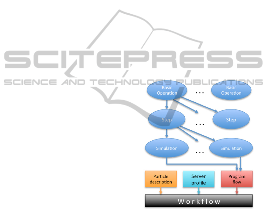
The third, (top) level of the hierarchy groups
simulations steps together in a well-defined order to
form a Simulation Specification, representing an
entire simulation. Parameter values that are public in
the simulation steps can still be altered by the users
prior to running the simulation. This hierarchical
structure is illustrated in Figure 1.
We generate simulator scripts from the
simulation specification as follows. As the
simulation contains simulation steps and steps
contain basic operations, the simulation
specifications have a tree structure. Parameter types
and default values are defined in the leaves, i.e. the
basic operations, and may be overridden at the
higher levels of the hierarchy. When traversing the
tree in the first pass, the code generator propagates
the overridden parameter values down to the leaves.
Once the parameter values have been computed, the
code generator starts to generate the simulator script.
Figure 1: Hierarchical representation of simulations.
For every simulation step, the code generator first
generates the initialization code of the step by
substituting the parameter values into the
initialization code templates of the basic operations
in the order they are contained. This is followed by
generating the body of the simulation step in the
same way, from the respective body code templates
of the basic operations. Finally, the finalization part
of the simulation step is generated, traversing the
contained basic operations in the reverse order. Each
simulation step is turned into a contiguous block of
SIMULTECH2013-3rdInternationalConferenceonSimulationandModelingMethodologies,Technologiesand
Applications
174
code, which are concatenated to form the complete
simulator script, maintaining the ordering of the
steps within the simulation specification. This code
generation scheme guarantees that a) allocated
resources can be used by other operations within the
same simulation step, that b) resources are properly
freed when not needed any more.
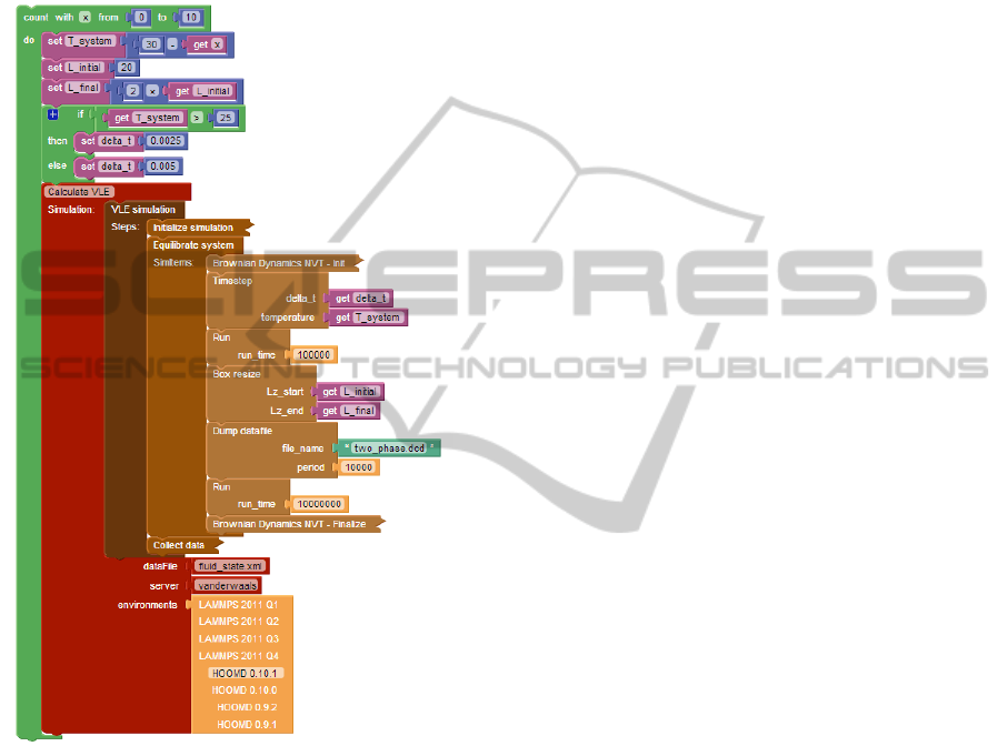
Figure 2: Program logic representation in a workflow.
3.2 Server Profiles
To run a simulation we need to set up specific
simulators on local servers or use remote systems.
To achieve this, we maintain a list of server profiles
where we can store configuration settings (e.g.
credentials to access the job manager (e.g. PBS),
number of cores used, etc.) that can be used for
running simulations.
3.3 Workflows
A workflow is the top level entity that connects
simulation logic with particle data and server
profiles. The user can load simulations into a
workflow, define custom parameters, and set up a
program flow that controls simulation execution.
This is supported through a visual programming
approach built on top of Blockly (Blockly, 2013).
An example workflow is shown in Figure 2. The
green blocks represent the program logic. In the
example in the figure, it iterates 11 times and sets
various variables. The maroon block represents one
simulation run using a specific simulation called
"VLE simulation" and a data file, server and
simulator specified as parameters. VLE simulation
consists of three simulation steps: Initialize
simulation, Equilibrate system and Collect data. The
Equilibrate system step shows how simulation steps
are further broken down into basic operations, like
running the simulation for a given number of steps,
or dumping the current state into a data file.
Individual parameters of basic operations may be
viewed or edited directly from the workflow, as
specified by the visibility rules of their containers
(basic operations or simulation steps).
3.4 Particle Description
One of the main ingredients of simulation inputs is
the data that includes the structure of particles,
connections and constraints between them, a
description of the simulation box and physical
properties of the particles that are present in the
system (e.g. position, velocity, electrical charge,
etc). To model the particles, we provide a web-based
visual editor that shows a list of atoms that are
contained by a nanoparticle with all necessary
properties, and also the connections and constraints
that are present between the atoms. With such a
visualizer, particle designers are less likely to make
mistakes with either particles or bonds. For setting
up data input files, we need to define a box that will
contain all our particles and set up a rule how our
small particle building block will be replicated
throughout the whole box. The information captured
via the web-based interface is used to generate the
actual data files for the various supported simulators.
4 SOFTWARE SYNTHESIS
Once the simulation has been designed, it is the
workflow specification that aggregates all the
required information: 1) the prototype of the
particles used in the simulation and the description
of how it will be replicated throughout the
simulation box, 2) the specification of the simulation
with the hierarchy of simulation steps and their basic
Web-basedMetaprogrammableFrontendforMolecularDynamicsSimulations
175
operations included, 3) the visual program
describing how the simulation needs to be repeatedly
run with all parameter values specified by the user
including the selected simulation engine and finally,
4) the necessary information about the target server.
The orchestration engine is an extensible
interpreter that executes the Blockly code. It can
process a) control flow blocks (conditional
branching, loops, function definitions and calls), b)
arithmetic and c) logic operator blocks, d) list and e)
string handling blocks, as well as f) variable
assignment and evaluation blocks. All other block
types are handled by external interpreter plugins. An
example of such an extrinsic block is the simulation
instance block, drawn in maroon in Figure 2.
When the orchestration engine encounters an
extrinsic block, it locates the interpreter plugin
registered for that particular block type, and invokes
it with the following parameters:
the relevant part of the abstract syntax tree,
including the extrinsic block itself and all of its
descendants,
the actual variable assignments as a key-value
map, and
the current stack frame.
The interpreter plugin may freely read, write and
define variables, and optionally, it may place a
return value on the stack, all of which are then
available for the orchestration engine after the plugin
completes.
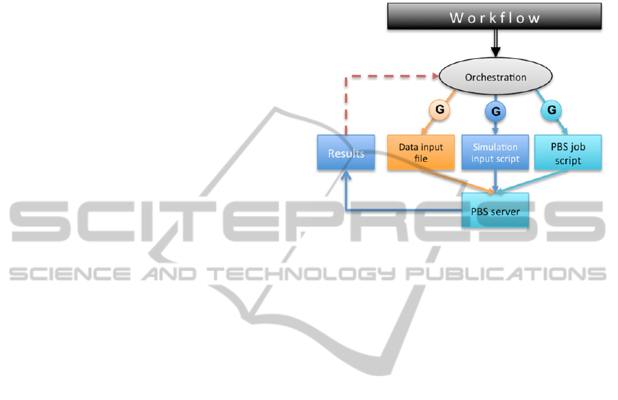
Let us look at a particular example. When the
orchestration engine encounters the simulation
instance block (drawn in maroon in Figure 2), the
simulation instance interpreter plugin is invoked. It
translates the series of simulation steps to simulator
scripts for the HOOMD 0.10.1 simulator target. The
parameter values delta_t, temperature, Lz_start and
Lz_end are taken from the actual values of delta_t,
T_system, L_initial and L_final in the variable
assignment map, respectively. The plugin then
generates the PBS scripts specific to the
vanderwaals server profile, and submits the job to
the server. The plugin periodically polls the job
status from the server. After the job is completed, it
collects the result data set and returns control back to
the orchestration engine.
While the simulation instance block has no
return value, many other extrinsic block types do
have one. In particular, blocks that describe data
analysis (e.g. the ratio of molecules in liquid and
vapor states) place their return value on the stack
before they exit. The orchestration engine may
assign this return value to variables, according to the
Blockly code describing the control flow. Such
variables can then be used in conditional branching,
allowing the workflow programmers to implement
algorithms that take into consideration the simulator
outcomes.
Figure 3: Synthesis and orchestration.
Once workflow execution is initiated, the system
provides real-time feedback on the status of the
entire process: system synthesis, file upload, job
status provided by the PBS scheduler (queued,
running, finished, etc). Once the results are
available, they are shown on the web interface.
Figure 3 illustrates the process.
As the entire process is automated, it frees the
users from going through this complicated and error-
prone process manually where they would need to
interact with multiple tools, set up server
connections, upload/download multiple files, place
them in the right path, set up simulator
configurations, and maintain simulator-generated
result files. In addition, the system provides a well-
structured and searchable backend for simulation
setups and results. This enables searching for
existing results potentially saving significant time
and CPU cycles. Also, the repeatability of
simulations is ensured because all setup information
down to the versions of tools used are saved along
with the end results.
5 SYSTEM ARCHITECTURE
From technical point of view we had to make several
decisions to create a useful and easy-to-use
application. In the very beginning, we decided to use
web-based technologies for the following reasons: as
we mentioned before, toolsets that are used by
chemical engineers are custom-made, hard to setup
SIMULTECH2013-3rdInternationalConferenceonSimulationandModelingMethodologies,Technologiesand
Applications
176
and organizing results of simulations are not solved
yet. A desktop-based solution would have multiple
downsides such as the fact that all users have to
setup all the tools they need to use for a simulation,
which is not easy because these common-used tools
are not always platform-independent, need custom
dependencies (as they need to be compiled on the
target machine). On the other hand, users have to
have access to their workstations always to be able
to work. Having a web-based solution, necessary
tools have to be installed and maintained (version
refresh, etc) only on the hosting servers.
A web-based solution also provides a higher
level of usability: most of the tools are command-
line tools and have a long learning curve to get
familiar with them, while on the web we can provide
an intuitive interface that is easy-to-use for users
who do not have any knowledge about certain tools.
The second design decision involves the
technology choices for easy data retrieval and
manipulation, while having a structured backend
system for archiving. A natural choice is to use a
database. An object database fits naturally with the
hierarchical representation of the simulations
utilized in our approach. Also, storing and retrieving
JSON-like documents/objects are supported by
NOSQL databases quite well.
Another key decision is the type of web-server to
utilize. As most of the server-side tools the system
needs to integrate are UNIX-based, a Microsoft-
based solution (i.e., Internet Information Server -
IIS) seemed suboptimal. Node.js, a relatively new
technology provides good performance and is very
flexible with interacting external tools. Its
programming language is Javascript which is also
used on the client-side as a de-facto standard for
web-based interactive user interface design. This
choice also saves development time as it enables
sharing code between server- and client-side.
Node.js relies on reusable packages called node
modules that provide certain functionalities or
custom APIs for external tools and also help
structure the application.
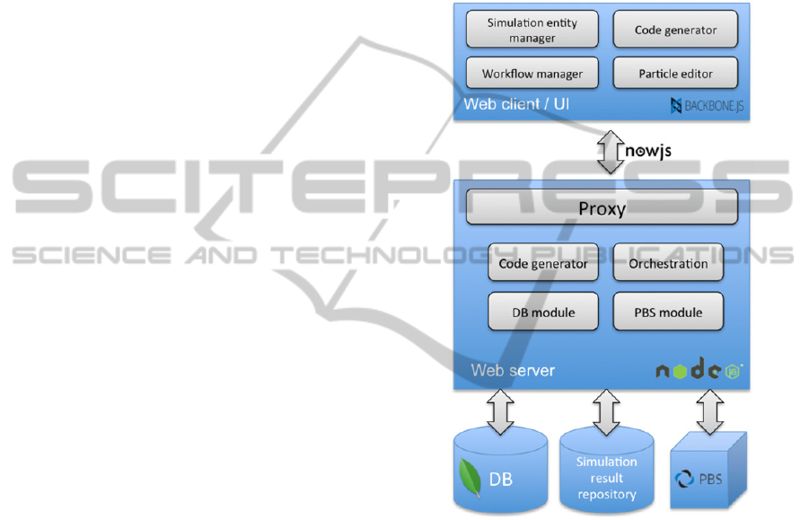
Figure 4 shows the prototype system
architecture. On the client side the application runs
in the browser and downloads/ synchronizes data
from the server. The widely used library,
Backbone.js that follows the Model-View-Controller
pattern, and require.js that provides a convenient
way to modularize and structure the source code are
utilized. The web-client has separate modules for
simulation design, workflow creation and particle
definition. A copy of the server-side code generator
is also included here for debugging and educational
purposes. Super users who develop simulation
components can immediately get feedback on what
the simulation script corresponding to their current
design will look like. This helps them debug their
design and also assists in finding bugs in the code
generator itself. Regular users can also utilize this
service to see the how their simulation designs
decisions will manifest themselves in the generated
code.
Figure 4: System architecture.
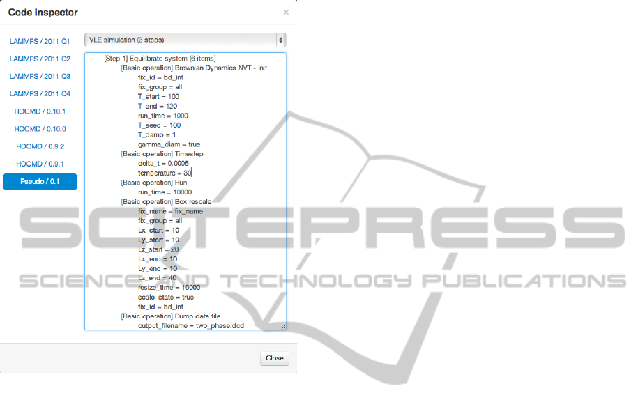
A handy tool helping both of these activities is the
ability of the code generator to output pseudo code
in the web client. This pseudo code is easy for
human readers to comprehend. It shows the structure
of the code that corresponds to the modeled system
without the complexity of the specific syntax of the
various target tools. Figure 5 shows the pseudo code
generated for a portion of the workflow depicted in
Figure 2.
On the server side multiple node.js instances are
included: a proxy that routes requests to the proper
instance to serve different data or files. The
Orchestration module includes the execution engine
that is responsible for interacting with local and
remote workers (e.g., PBS servers, Simulation result
repositories, etc.). The server-side architecture is
inherently scalable. To separate certain parts or
Web-basedMetaprogrammableFrontendforMolecularDynamicsSimulations
177
functionalities (e.g. switching to a stand-alone
database server, creating a second file server for raw
simulation output files, etc.) only the configuration
settings need to be modified.
Figure 5: Example generated pseudo code.
A custom node module interacts with PBS: it uses
ssh and scp to run commands and to
upload/download files, monitors queued/running
jobs and interacts automatically when certain job
status changes happen. As we use node.js on the
server-side, a natural transition from the
conventional one-way communication method
(RESTful interface) to a two-way communication
method (through WebSockets) proved very useful:
users can be notified about any job status (or data)
changes without refreshing a page or polling the
server. This makes the user interface interactive, and
easy-to-use and provides up-to-date information
while eliminating most common errors when users
interact with the domain-specific toolchain.
6 CONCLUSIONS
The technology described in this paper has the
potential to revolutionize how molecular dynamics
simulations are carried out by the scientific
community. The framework makes it possible to
capture the deep knowledge of the few individuals
who are intimately familiar with the various
simulation tools frequently used in the domain and
make it available at a much higher level of
abstraction for the wider community through a user-
friendly, intuitive web interface. We envision that a
rich library of simulation modules and templates will
be developed. In addition, the results of MD
simulations will also be archived and made available
in a fully searchable form. The results will be tightly
coupled with the exact simulation setup that was
used to create it. This will make it easy for people to
find existing results, recreate them if necessary or
build upon them in their own research. Today such a
collaborative infrastructure simply does not exist.
ACKNOWLEDGEMENTS
The research presented in this paper was supported
by the National Science Foundation grants NSF
CBET-1028374 and NSF OCI-1047828.
REFERENCES
Blockly, 2013. http://code.google.com/p/blockly/
Nanohub, 2013. http://www.nanohub.org/
MDAPI, 2013. http://www.ks.uiuc.edu/Development/
MDTools/mdapi
Atomic Simulation Environment, 2013. https://wiki.
fysik.dtu.dk/ase/
Etomica, 2013. http://etomica.org/
Plimpton, S. J., 1995. Fast Parallel Algorithms for Short-
Range Molecular Dynamics. In J Comp Phys, 117, 1-19.
HOOMD-Blue web page, 2013. http://codeblue.umich.
edu/hoomd-blue/
Anderson, J.A., Lorenz, C.D., Travesset, A., May 2008.
General purpose molecular dynamics simulations fully
implemented on graphics processing units. In Journal
of Computational Physics, 227(10): 5342-5359,
10.1016/j.jcp.2008.01.047
Perrone, L. F., Main, C. S., and Ward, B. C., 2012. Safe:
simulation automation framework for experiments. In
Proceedings of the Winter Simulation Conference, ser.
WSC '12.
Rybacki, S., Himmelspach, J. , Haack, F., and
Uhrmacher, A. M., 2011. WorMS -- a framework to
support workflows in M&S. In Proceedings of the
Winter Simulation Conference, ser. WSC '11.
SIMULTECH2013-3rdInternationalConferenceonSimulationandModelingMethodologies,Technologiesand
Applications
178
