
Effects of Wall Roughness, Impeller Blades and Diffuser Vanes
on the Performances of a First Stage Centrifugal Pump
Nicolas La Roche-Carrier, Guyh Dituba Ngoma and Walid Ghie
University of Quebec in Abitibi-Témiscamingue, School of Engineering 445,
Boulevard de l’Université, Rouyn-Noranda, Quebec, J9X 5E4, Canada
Keywords: Centrifugal Pump, Multistage, Impeller, Diffuser, Computational Fluid Dynamics (CFD), Modeling and
Simulation.
Abstract: In this study, the first stage of a multistage centrifugal pump was numerically investigated to improve its
design. The continuity and Navier-Stokes equations with the k- turbulence model and standard wall
functions were used. The effects of the wall roughness height, impeller blade height and diffuser vane
height, and the number of diffuser vanes on the performances of the first pump stage were analyzed. The
results achieved demonstrate that the selected parameters affect the pump stage head, brake horsepower and
efficiency in a strong yet different manner. To validate the approach developed, the results of the numerical
simulations were compared with the experimental results.
1 INTRODUCTION
Multistage centrifugal pumps are widely used in
industrial and mining enterprises. One of the most
important components of a multistage centrifugal
pump is the impeller (Peng, 2008). For a more
performing multistage pump, its design parameters
must be determined accurately. Given the three-
dimensional and turbulent liquid flow in a multistage
centrifugal pump, it is very important to be aware of
the liquid flow’s behavior when flowing through a
pump stage accounting for the wall roughness. This
can be achieved by taking all stage components into
consideration in the planning, design and
optimization phases in design and off-design
conditions.
Many experimental and numerical studies have
been conducted on the liquid flow through a
multistage centrifugal pump. A three-dimensional
turbulent flow through an entire stage of a
multistage centrifugal pump was numerically
simulated using a CFD code (Huang et al., 2006),
including flows in a rotating impeller and stationary
diffuser. It was found that the reverse flows existed
near the impeller outlet, resulting in the flow field
being asymmetric and unstable. Moreover, the
impacts of the return vane profile on the
performances of the multistage centrifugal pump
were experimentally investigated to optimize the
stationary components in the multistage centrifugal
pump (Miyano et al., 2008). It was found, among
other things, that the return vane, whose trailing
edge was set at the outer wall radius of the
downstream annular channel and discharged the
swirl-less flow, had a positive impact on pump
performances, while the effects of the diffuser vane
on the performances of the multistage centrifugal
pump were experimentally investigated (Kawashima
et al., 2008), accounting for the interactions among
the diffuser vane, return vane and next stage
impeller. The relevance in matching the diffuser
vane and return vane properly to improve the pump
efficiency of the multistage centrifugal pump was
shown. In addition, the multistage pump problems in
conjunction with the axial thrust were
experimentally examined (Gantar et al., 2002), the
Laser Doppler Anemometry (LDA) was used to
determine the fluid rotation in the impeller side
chamber and its impact on the impeller hydraulic
axial thrust for different leakage flow regimes.
Deepened analysis of previous studies clearly
demonstrated that the research results obtained are
specific to the design parameters and configuration
of the rotating and stationary components in
multistage centrifugal pumps, and thus cannot
always be generalized. Therefore, in this study, to
improve the design and performances of multistage
361
La Roche-Carrier N., Dituba Ngoma G. and Ghie W..
Effects of Wall Roughness, Impeller Blades and Diffuser Vanes on the Performances of a First Stage Centrifugal Pump .
DOI: 10.5220/0004486903610368
In Proceedings of the 3rd International Conference on Simulation and Modeling Methodologies, Technologies and Applications (SIMULTECH-2013),
pages 361-368
ISBN: 978-989-8565-69-3
Copyright
c
2013 SCITEPRESS (Science and Technology Publications, Lda.)
centrifugal pumps, accounting for the particularities
of the geometry and configuration of the impeller
and diffuser with return vanes, a numerical
investigation was conducted using the ANSYS-CFX
code (Ansys inc., 2011) based on the finite volume
method and Rhie Chow algorithm for the pressure-
velocity coupling. This was done to gain further
insight into the characteristics of the three-
dimensional turbulent liquid flow through a stage of
a multistage centrifugal pump while also considering
various flow conditions, the height of the wall
roughness, the heights of the impeller blade and
diffuser vane, and the number of diffuser vanes.
Moreover, the pump stage head, brake horsepower
and efficiency were represented as a function of the
flow rate in order to identify the values of selected
design parameters that might enhance pump stage
performances with respect to their value ranges.
2 GOVERNING EQUATIONS
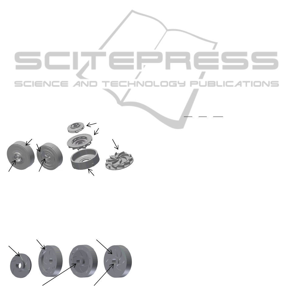
Fig. 1 shows the model of the first stage of a
multistage centrifugal pump considered in this study.
It consists of an impeller, diffuser with return vanes
and casting.
a) Pump stage b) Stage components
Figure 1: Model of a centrifugal pump stage.
To run the numerical simulations, the used domain
fluids of the impeller and diffuser with return vanes
are shown in Fig. 2.
Suction side (inlet) Discharge side (outlet)
Figure 2: Domain fluids of impeller, diffuser and pump
stage.
In the centrifugal pump stage’s governing equations
for liquid flow, the following assumptions were
made: (i) a steady state, three-dimensional and
turbulence flow using the k- model was assumed;
(ii) it was an incompressible liquid; (iii) it was a
Newtonian liquid; and (iv) the liquid’s
thermophysical properties were constant with the
temperature (density, viscosity, etc.).
To account for these assumptions, the theoretical
analysis of the liquid flow in the impeller passages,
diffuser vane passages and diffuser return vane
passages was based on the continuity and
Navier-Stokes equations (Tropea et al., 2007). For
the three-dimensional liquid flow through these
components of a centrifugal pump stage as shown in
Fig. 2, the continuity equations are expressed by:
0V.
vel
,
(1)
where
z,y,xw,z,y,xv,z,y,xuVV
velvel
is the
liquid flow velocity vector.
Using the coordinate system, Eq. 1 can be rewritten
as:
0
z
w
y
v
x
u
(2)
and the Navier–Stokes equations are given by:
B p
))V(V.()VV.(
T
velveleffvelvel
(3)
where p is the pressure, is the density,
eff
is the
effective viscosity accounting for turbulence, is a
tensor product and B is the source term, which is
equal to zero for the flow in the stationary
components like the diffuser.
For flows in an impeller rotating at a constant speed
, the source term can be written as follows:
rxxVx2B
vel
(4)
where
r
is the location vector,
vel
Vx2
is the
centripetal acceleration and
rxx
is the Coriolis
acceleration.
Using the coordinate system, Eq. 3 can be rewritten
as:
Inlet
Back stage side
Outlet
Return vanes
Blades
Vanes
Impeller
Diffuser with
Return vanes
Casing
SIMULTECH2013-3rdInternationalConferenceonSimulationandModelingMethodologies,Technologiesand
Applications
362

22
22
2
2
22
22
2
2
eff
x
eff
uu u uu
uvw
xy z xy
up
B
xz
vv v vv
uvw
xy z xy
v
z
22
22
2
2
y
eff
z
p
B
y
ww w ww
uvw
xy z xy
wp
B
zz
(5)
where
.0B and u2rB ,v2rB
zzy
2
zyzx
2
zx
Furthermore,
eff
is defined as
teff
, where
is the dynamic viscosity and
t
is the turbulence
viscosity, it
is linked to turbulence kinetic energy k
and dissipation ε via the relationship:
12
t
kC
where C
is a constant.
The values for k and stem directly from the
differential transport equations for turbulence kinetic
energy and turbulence dissipation rates:
k
k
t
vel
p]k).[()kV.(
(6)
)CpC(
k
]).[()V.(
2k1
t
vel
(7)
where C
1
, C
2
and
are constants. p
k
is the
turbulence production due to viscous and buoyancy
forces, which is modeled using:
)kV.3(V.
3
2
p )VV.(Vp
veltvel
kb
T
velvelveltk
(8)
.gp
t
kb
(9)
where p
kb
can be neglected for the k- turbulence
model.
Additionally, for the flow modeling near the wall,
the logarithmic wall function is used to model the
viscous sub-layer (Tropea et al., 2007).
To solve equations 2 and 5 numerically while
accounting for the boundary conditions and
turbulence model k-, the ANSYS-CFX code. In the
cases examined involving the pump stage, the
boundary conditions were formulated as follows: the
static pressure provided was given at the stage inlet,
while the flow rate provided was specified at the
stage outlet. The frozen rotor condition was used for
the impeller-diffuser interface. A no-slip condition
was set for the flow at the wall boundaries.
The pump stage head is determined as follows:
g
pp
H
tito
(10)
where p
ti
is the total pressure at the pump stage inlet
and p
to
the total pressure at the pump stage outlet as
shown in Fig. 2. They are expressed as:
2
vel
iti
i
V
2
pp
and
2
vel
oto
o
V
2
pp
(11)
Moreover, the hydraulic power of the pump stage is
given by
QgHP
h
, where Q is the flow rate and H
is the pump stage head.
In addition, the brake horsepower of the pump stage
is expressed as P
s
= C, where is the angular
velocity and C is the impeller torque.
From the hydraulic power and the brake horsepower,
the efficiency of the pump stage can be written as
s
h
P
P
. It can also be formulated in terms of the
hydraulic efficiency (
h
), the volumetric efficiencies
(
v
), and mechanical efficiency (
m
) as =
h
v
m
.
3 RESULTS AND DISCUSSION
Water at 25 °C was used as the working liquid for all
simulation runs in this study. The main reference
data used for the impeller were 195 mm for the inner
diameter, 406 mm for the outer diameter, 6 for the
number of blades and 1750 rpm for the rotating
speed. For the diffuser, the main reference data were
407.016 mm for the inner diameter, 571.5 mm for
the outer diameter, 11 for the number of vanes and 8
for the number of return vanes. The numerical
simulation results presented in this work were
obtained with the highest accuracy by conducting
mesh-independent solution tests in each case study
using different numbers of mesh elements.
3.1 Impact of Wall Roughness Height
To analyze the impact of the wall roughness height
of the impeller, diffuser and casting on the pump
stage performances, two wall roughness heights (0
mm, and 2 mm) were chosen, while the other
EffectsofWallRoughness,ImpellerBladesandDiffuserVanesonthePerformancesofaFirstStageCentrifugalPump
363
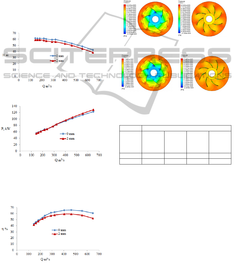
parameters were kept constant. Fig. 3 shows the
head as a function of the flow rate, where it is
observed that the head is not affected by the value of
the wall roughness height at 0 mm. On the contrary,
it decreases when the wall roughness height
increases further. This is explained by the fact that
the friction loss rises with significantly increasing
wall roughness height. In other words, the wall
roughness increases the flow resistance in turbulent
flow. As shown in Fig. 4, the brake horsepower rises
with increasing wall roughness height for large flow
rates due to the increase in the friction loss with
increasing wall roughness height for large flow
rates. Thus, the requested pump torque increases.
Figure 3: Pump stage head versus flow rate.
Figure 4: Brake horsepower versus flow rate.
In addition, Fig. 5 shows the efficiency as a function
of the flow rate, where it is observed that the
efficiency decreases with increasing wall roughness
height due to the increase in friction loss.
Figure 5: Efficiency versus flow rate.
Moreover, Fig. 6 shows the corresponding static
pressure contour for Q = 464 m
3
/h, which
demonstrates the distribution of static pressure in the
impeller and diffuser with return vanes. Also, Tab. 1
presents the pressure differences in the impeller,
diffuser and diffuser return vane passages obtained
for the wall roughness heights of 0 mm and 2 mm.
There, the decrease in total pressure difference with
increasing wall roughness height is shown.
Diffuser return vane passages
a) 0 mm and ∆p = 519683 Pa
Diffuser return vane passages
b) 2 mm and ∆p = 486555 Pa
Figure 6: Static pressure contour.
Table 1: Distribution of pressure difference.
Pressure difference ∆p Pa
Wall
rough.
height
mm
Impeller Diffuser Diffuser
return
vane
passages
∆p
total
0 512751 108942 -102010 519683
2 486786 79951 -80182 486555
3.2 Impact of the Height of Impeller
Blades and Diffuser Vanes
To investigate the impact of the height of impeller
blades and diffuser vanes on the pump stage
performances, the values of 16 mm, 23 mm and 29
mm were selected for the impeller blade height and
diffuser vane height, while keeping the other
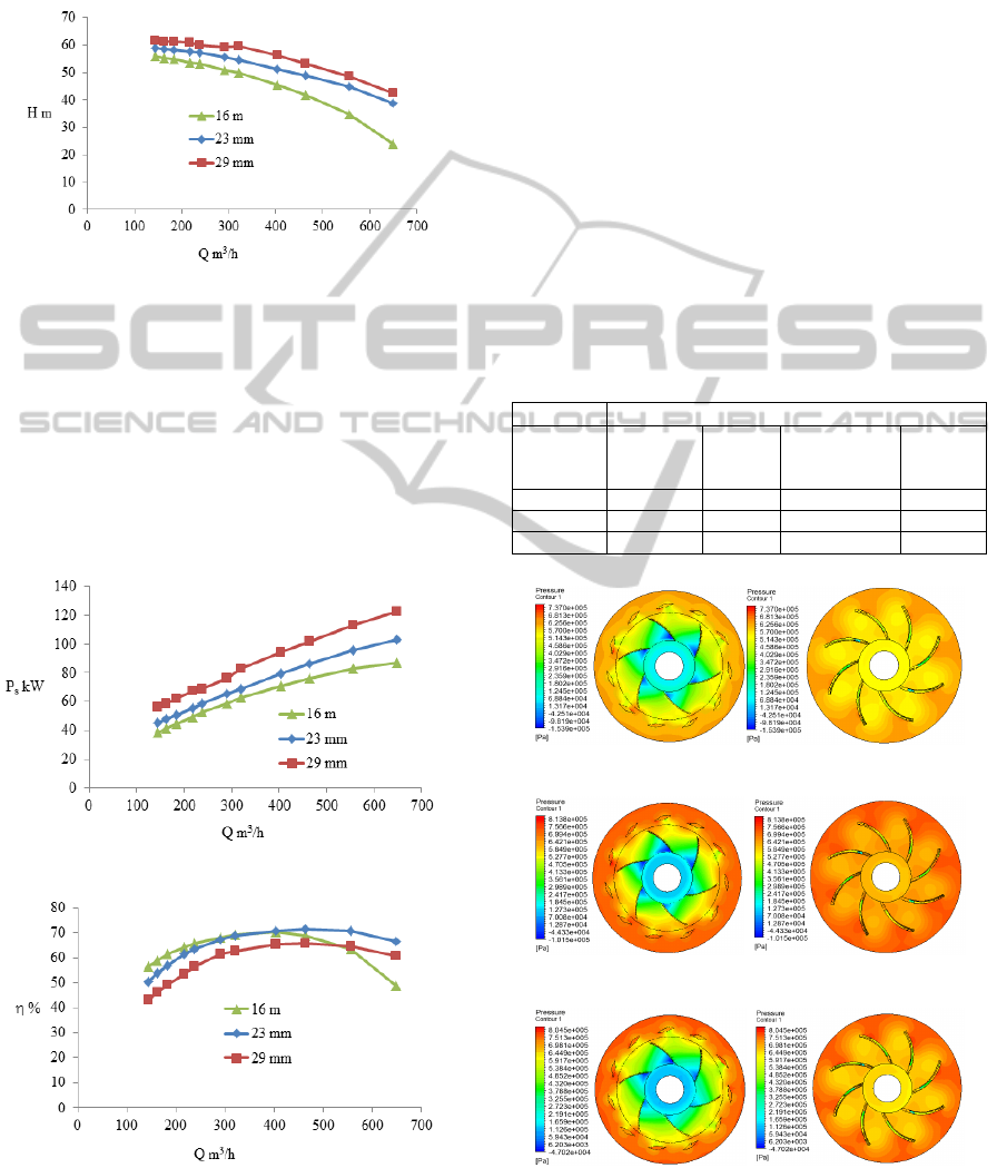
parameters constant. Fig. 7 shows that the pump
stage head decreases with increasing flow rate due to
decreasing liquid pressure. In addition, the pump
stage head increases with increasing blade height
and vane height. This is explained by the fact that
when the flow rate is kept constant, the increased
blade height leads to the decreasing meridional
velocity, which increases the pump stage head since
SIMULTECH2013-3rdInternationalConferenceonSimulationandModelingMethodologies,Technologiesand
Applications
364
the outlet tangential velocity and outlet blade angle
remain constant. In other words, the liquid pressure
drops in the impeller and the diffuser decreases as a
function of the increase in the blade height and vane
height.
Figure 7: Pump stage head versus flow rate.
Furthermore, the curves expressing the pump stage
brake horsepower as a function of the flow rate are
shown in Fig. 8, illustrating that the brake
horsepower increases with increasing flow rate. This
is explained by the additional decrease in liquid
pressure relative to the flow rate. Also, the brake
horsepower increases relative to the impeller blade
height due to the requested increase in pump shaft
torque relative to the increased blade height.
Figure 8: Brake horsepower versus flow rate.
Figure 9: Efficiency versus flow rate.
In addition, Fig. 9 shows that the efficiency for the
blade height and vane height of 16 mm decreases
rapidly to the right of the BEP. The efficiency of the
blade height and vane height of 23 mm is highest at
large flow rates, whereas the efficiency of the blade
height and vane height of 29 mm is lowest at flow
rates ranging between 150 m
3
/h and 550 m
3
/h.
Figs. 10 and 11 represent the corresponding
contours for static pressure and liquid flow velocity
vectors for Q = 464 m
3
/h. Fig. 10 clearly shows that
the static pressure increases with increasing blade
height and vane height. This is due mainly to the
decrease in liquid flow velocity at the impeller outlet
as depicted in Fig. 11, where the average liquid flow
velocities at the impeller outlet decrease from 18.43
for 16 mm to 15.67 m/s for 29 mm. Also, the
recirculation phenomenon is observed in the diffuser
return vane passages. Furthermore, the distribution
of pressure difference (∆p = p
o
- p
i
) in the stage
components is presented in Tab. 2.
Table 2: Distribution of the pressure difference.
Pressure difference ∆p Pa
Blade or
vane height
mm
Impeller Diffuser
Diffuser return
vane passages
∆p
total
16 424908 74626 -91742 407792
23 485468 92713 -98754 479427
29 512751 108942 -102010 519683
Diffuser return vane passages
a) Height = 16 mm and ∆p = 407792 Pa
Diffuser return vane passages
b) Height = 23 mm and ∆p = 479427 Pa
Diffuser return vane passages
c) Height = 29 mm and ∆p = 519683 Pa
Figure 10: Static pressure contour.
EffectsofWallRoughness,ImpellerBladesandDiffuserVanesonthePerformancesofaFirstStageCentrifugalPump
365
Diffuser return vane passages
a) Height
= 16 mm
Diffuser return vane passages
b) Height
= 23 mm
Diffuser return vane passages
c) Height
= 29 mm
Figure 11: Liquid flow velocity vector.
3.3 Impact of the Number of Diffuser
Vanes
To examine the impact that the number of diffuser
vanes has on the pump stage head, brake horsepower
and efficiency, three diffuser models (with 7, 8 and
12 vanes, and 8 return vanes) were selected
considering an impeller with 5 blades, while other
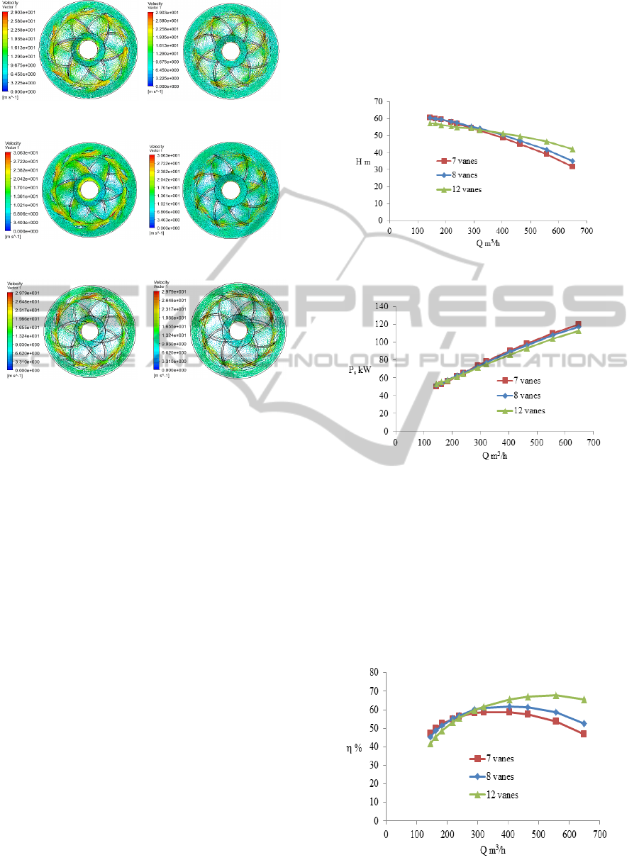
parameters were kept constant. Fig. 12 shows the
head as a function of the flow rate, where it is
observed that the head obtained with diffusers with 7
and 8 vanes is almost the same for a flow rate
smaller than 320 m
3
/h, whereas the head with the
diffuser with 12 vanes is smallest. For large flow
rates, the head with the diffuser with 12 vanes is the
highest. This is due to a rise in static pressure
through the reduction in flow velocity in a diffuser.
The flow guidance and friction effect depend on the
number of diffuser vanes, and the flow rate. When
the number of diffuser vanes increases, the diffuser
vane passages become narrower. This leads to better
fluid guidance. In other words, flow loss decreases
as the number of diffuser vanes increases. Friction
loss increases with an increasing number of diffuser
vanes. Furthermore, flow guidance, friction loss and
static pressure conversion are affected by the flow
rate. Thus, there is an antagonistic impact between
the diffusion impact and the friction loss in the range
of the flow rate considered. As depicted in Fig. 13,
brake horsepower variation due to the number of
diffuser blades is also small, even if the lowest brake
horsepower is reached with 12 diffuser blades.
Figure 12: Pump stage head versus flow rate.
Figure 13: Brake horsepower versus flow rate.
In addition, Fig. 14 shows that for low and high flow
rates, the efficiency of 12 diffuser vanes is highest
whereas the efficiency for 7 and 8 diffuser vanes is
nearly the same for a flow rate smaller than 320
m
3
/h. This figure also indicates that the efficiency is
lowest for 7 diffuser vanes for a flow rate higher
than 320 m
3
/h. Moreover, the BEP moves towards
large flow rates and rises as the number of diffuser
vanes increases.
Figure 14: Efficiency versus flow rate.
SIMULTECH2013-3rdInternationalConferenceonSimulationandModelingMethodologies,Technologiesand
Applications
366
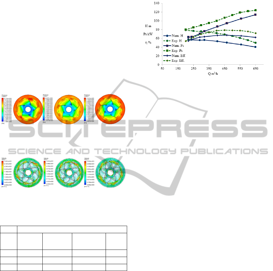
Furthermore, Figs. 15 and 16 show the
corresponding static pressure contour and liquid
flow velocity vector for Q = 403 m
3
/s, respectively,
illustrating that for these figures, there is a
correlation between increased static pressure
difference and decreased liquid flow velocity at the
diffuser outlet, with an increased diffuser vane
number. The average liquid flow velocity values at
the diffuser outlet of 13.94 m/s, 13.14 m/s and 11
m/s were found for 7, 8 and 12 vanes respectively,
as shown in Fig. 16. Also, Tab. 3 indicates the
pressure difference in the impeller, diffuser and
diffuser return vane passages.
a) 7 vanes b) 8 vanes c) 12 vanes
∆P = 482224 Pa ∆P = 498668 Pa ∆P = 500843 Pa
Figure 15: Static pressure contour.
a) 7 vanes b) 8 vanes c) 12 vanes
Figure 16: Vectors of liquid flow velocity.
Table 3: Distribution of pressure difference.
Pressure difference ∆p Pa
Vane Impeller Diffuser
Diffuser
return vane
passages
∆p
total
7 5 10556 70817 -89149 482224
8 496559 87279 -85170 498668
12 476198 103252 -78607 500843
3.4 Model Comparison
To validate the model developed for the first pump
stage, the numerical simulation results were
compared with the experimental results (Technosub
inc.), as shown in Fig. 17, where it is observed that
all the numerical curves for the head, brake
horsepower and efficiency follow the trend of the
experimental curves; however, additional
parameters, which affect the gap between the
numerical results and experimental results are being
more thoroughly investigated in the experimental
and numerical sides to increasingly enhance the
approach developed for the first pump stage.
Figure 17: Comparison between the numerical and
experimental results.
4 CONCLUSIONS
In this work, a liquid flow in the first stage of a
multistage centrifugal pump was numerically
examined. A model of a first pump stage was
developed to analyze the impacts of the wall
roughness height; the height of the impeller blades
and diffuser vanes, and the number of diffuser vanes
on the pump stage performances. The results
achieved reveal, among other things, that higher wall
roughness heights of the impeller and diffuser
negatively affect the pump stage head, brake
horsepower and efficiency; the pump stage head and
brake horsepower increase as the height of the
impeller blades and diffuser vanes increases.
Moreover, the pump stage head and efficiency rise
for large flow rates with increasing numbers of
diffuser vanes, whereas the brake horsepower hardly
varies at all regardless of the number of diffuser
vanes. In all, the numerical curves obtained for the
head, brake horsepower and efficiency well follow
the trend of the experimental results.
NOMENCLATURE
B source term (Nm
-3
)
C torque (Nm)
g acceleration of gravity (ms
-2
)
H head (m)
P power (W)
p pressure (Nm
-2
)
p
turbulence production due to viscous and
buoyancy forces
Q flow rate (m
3
s
-1
)
r radial coordinate (m)
V velocity (ms
-1
)
u flow velocity in x direction (ms
-1
)
EffectsofWallRoughness,ImpellerBladesandDiffuserVanesonthePerformancesofaFirstStageCentrifugalPump
367

v flow velocity in y direction (ms
-1
)
w flow velocity in z direction (ms
-1
)
x x-coordinate (m)
y y-coordinate (m)
z z-coordinate (m)
Greek symbols
difference
turbulence dissipation (m
2
s
-3
),
efficiency
turbulence kinetic energy (kg m
-2
s
-2
)
fluid density (kg m
-3
)
dynamic viscosity (Pa s)
eff
effective viscosity (Pa s)
t
turbulence viscosity (Pa s)
Ω angular velocity (rad s
-1
)
Subscripts
1 inlet
2 outlet
h hydraulic
i inlet
m mechanical
o outlet
s shaft
t total
v volumetric
vel velocity
ACKNOWLEDGEMENTS
The authors are grateful to the Foundation of
University of Quebec in Abitibi-Temiscamingue
(FUQAT) and the company Technosub inc.
REFERENCES
Peng W., 2008. Fundamentals of turbomachinery.
Hoboken, New Jersey, John Wiley and Sons
.
Huang S., Islam M.F., Liu P., 2006. Numerical simulation
of 3 D turbulent flow through an entire stage in a
multistage centrifugal pump.
International Journal of
Computational Fluid Dynamics,
Vol. 20, Issue 5,
Pages 309-314.
Miyano M., Kanemoto T., Kawashima D., Wada A., Hara
T., Sakoda K., 2008. Return Vane Installed in
Multistage Centrifugal Pump.
International Journal of
Fluid Machinery and Systems
Vol. 1, No. 1.
Kawashima D., Kanemoto T., Sakoda K., Wada A., Hara
T., 2008. Matching Diffuser Vane with Return Vane
Installed in Multistage Centrifugal Pump.
International Journal of Fluid Machinery and
Systems
, Vol. 1, No. 1.
Gantar M., Florjancic D., and Sirok B., 2002. Hydraulic
Axial Thrust in Multistage Pumps - Origins and
Solutions.
Journal Fluids Engineering, Vol. 124, Issue
2, 336-341.
Ansys inc., 2011.
ANSYS-CFX (CFX Introduction, CFX
Reference Guide, CFX Tutorials, CFX-Pre User's
Guide, CFX-Solver Manager User's Guide, CFX-
Solver Modeling Guide, CFX-Solver Theory Guide)
,
release 14.0, USA.
Tropea C., Yarin A. L., Foss J. F., 2007.
Handbook of
experimental fluid mechanics
. Springer-Verlag, Berlin,
Heidelberg.
Technosub Inc., www.technosub.net.
SIMULTECH2013-3rdInternationalConferenceonSimulationandModelingMethodologies,Technologiesand
Applications
368
