
Efficient Coupled PHY and MAC use of Physical Bursts by
ARQ-Enabled Connections in IEEE 802.16e/WiMAX Networks
Oran Sharon
1
, Amit Liron
2
and Yaron Alpert
3
1
Department of Computer Science, Netanya Academic College, 1 University St., Netanya 42365, Israel
2
Department of Computer Science, Haifa University, Israel
3
LANTIQ, Ra’anana, Israel
Keywords:
WiMAX, Bursts, FEC Blocks, Data Blocks, Goodput.
Abstract:
In this paper we address an aspect of the mutual influence between the PHY layer budding blocks (FEC
Blocks) and the MAC level allocations in the Uplink and Downlink of IEEE 802.16e/WiMAX networks. In
these networks it is possible to transmit MAC level frames, denoted MAC PDUs, such that a PDU contains an
integral number of fixed size Data Blocks. PDUs are transmitted over PHY Bursts, which are divided into FEC
Blocks. We suggest an algorithm that computes the best way to define PDUs in a Burst in order to maximize
the Burst Goodput. We also give guidelines on how to choose the best Modulation/Coding Scheme (MCS) to
use in the Burst, given the SNR of the channel.
1 INTRODUCTION
Broadband Wireless Access (BWA) networks consti-
tute one of the greatest challenges for the telecom-
munication industry in the near future. These net-
works fulfill the need for range, capacity, mo-
bility and QoS support from wireless networks.
IEEE 802.16e (IEEE, 2005), also known as
WiMAX(Worldwide Interoperability for Microwave
Access) is the industry name for the standards being
developed for broadband access.
IEEE 802.16e is a cell based, Point-to-MultiPoint
(PMP) technology, providing high throughput in
Wireless Metropolitan Area networks (WMANs).
The IEEE 802.16e standard reference model includes
the Physical and Medium Access Control (MAC) lay-
ers of the OSI protocol stack. Multiple physical layers
are supported, operating in the 2 to 66 GHz frequency
spectrum and supporting single and multi-carrier air
interfaces, each suited to a particular environment.
For IEEE 802.16e to be able to fulfill the promise
for high speed service, it must efficiently support ad-
vanced Modulation and Coding schemes (MCSs) and
progressive scheduling and allocation techniques.
In this study we focus on the influence between
the PHY layer budding blocks (FEC Blocks) and
the length/location of the MAC layer frames de-
noted as MAC PDUs, in the Uplink and Downlink of
IEEE 802.16e systems, assuming that Data Blocks are
transmitted in the PDUs, as will be explained later.
1.1 The IEEE 802.16e/WiMAX
Network Structure
IEEE 802.16e/WiMAX is a standard for a Broadband
Wireless Access (BWA) network (IEEE, 2005) which
enables home and business subscribers high speed
wireless access to the Internet and to Public Switched
Telephone Networks (PSTNs). The system is com-
posed of a Base Station (BS) and subscribers, de-
noted as Mobile Stations (MSs), in a cellular architec-
ture. The transmissions in a cell are usually Point-to-
Multipoint, where the BS transmits to the subscribers
on a Downlink channel and the subscribers transmit
to the BS on an Uplink channel.
A common PHY layer used in IEEE 802.16e
is Orthogonal Frequency Division Multiple Access
(OFDMA) in which transmissions are carried in
transmission frames (IEEE, 2005). Every frame is a
matrix in which one dimension is a sub-channel (band
of frequencies) and the other dimension is time. A
cell in the matrix is denoted as a slot. The number of
data bits that can be transmitted in a slot is a function
of the Modulation and Coding scheme (MCS) that is
used in the slot.
A Burst in a frame is a subset of consecutive slots
sharing the same MCS, which is designated to a sub-
191
Sharon O., Liron A. and Alpert Y..
Efficient Coupled PHY and MAC use of Physical Bursts by ARQ-Enabled Connections in IEEE 802.16e/WiMAX Networks.
DOI: 10.5220/0004490201910198
In Proceedings of the 10th International Conference on Signal Processing and Multimedia Applications and 10th International Conference on Wireless
Information Networks and Systems (WINSYS-2013), pages 191-198
ISBN: 978-989-8565-74-7
Copyright
c
2013 SCITEPRESS (Science and Technology Publications, Lda.)

set of MSs for their transmissions. In the most com-
mon case a Burst is designated to a single MS, and this
is the case that we consider in this paper. In this paper
we assume that the Convolutional Turbo Code (CTC)
is used as the coding scheme, and in this case a Burst
also maps Forward Error Correction (FEC) Blocks to
the slots. In this paper knowing the details behind the
FEC technology is unnecessary so we will not elabo-
rate on this subject. The only property needed is that
all the data bits in a FEC Block have some probability
p to arrive successfully at the receiver.
1.2 Transmissions in IEEE 802.16e
Systems
The BS and the MSs transmit Protocol Data Units
(PDU) within Bursts. The MAC layer of IEEE
802.16e is connection oriented and PDUs, which are
the MAC level frames, thus belong to MAC connec-
tions (IEEE, 2005). Within PDUs the BS and the
MSs transmit their application packets that are de-
noted Service Data Units (SDU). An SDU can be an
IP packet, ATM cells, etc. The PDUs are used to
map SDUs into the MAC connections, to protect the
SDUs from transmission errors, to enable encryption
of the SDUs, etc. Each PDU has a fixed header, de-
noted Generic MAC Header (GMH). This header is
mainly used to associate a PDU to a MAC connec-
tion. Optionally, a PDU also has a CRC field. Any of
the other aforementioned functions performed on the
PDU payload requires an additional subheader. All
the (sub)headers within a PDU are considered to be
PDU overhead.
Let p be the probability that all the bits of a FEC
Block, after decoding, arrive correctly at the receiver.
This probability is a function of several parameters
such as the Coding rate, the number of decoding
iterations in the case of Turbo codes (Huang, 1997),
the Signal-to-Noise Ratio (SNR) of the channel and
the length, in bits, of the FEC Block (Huang, 1997). p
is bigger for longer FEC Blocks. In this paper, based
on (Alpert et al., 2013), we assume that all the FEC
Blocks are of the same size and that p is similar for
all the FEC Blocks of a transmission frame, i.e. there
is no correlation dependency between the success
probabilities of FEC Blocks of the same size in a
transmission frame.
The probability Q that a PDU arrives correctly at
the receiver is the probability that all its bits arrive
correctly. This is also the probability that all the FEC
Blocks that contain a part of the PDU arrive correctly.
1
Thus, in view of the above assumption on p, if a PDU
is transmitted within X FEC Blocks, holds Q = p
X
.
In this paper we concentrate on one type of MAC
connections, ARQ-enabled connections. In such con-
nections the SDUs are divided into Blocks, denoted
Data Blocks, of the same size. This size is defined at
the time when a connection is established. In the case
where the length of an SDU is not an integral number
of the Data Block size, the last Data Block of the SDU
is shorter, but it is not padded.
The purpose of the division into Data Blocks is to
enable the transmitter to know whether the SDUs it
transmits arrive successfully at the receiver. This is
accomplished by ARQ Feed-backs that are transmit-
ted back from the receiver to the transmitter. The re-
ceiver notifies the transmitter about every Data Block
whether it arrived successfully or not. In the case
where a Data Block is not received successfully, it
is retransmitted by the transmitter. The only correct-
ness check that a receiver is performing is in the PDU
level. Thus, the receiver considers all the Data Blocks
in a PDU as either arriving correctly or not.
In this paper we focus on the following question:
Given the Signal-to-Noise Ratio (SNR) of the chan-
nel, a Burst and a MCS, which determines the size
and number of FEC Blocks in the Burst, and the suc-
cess probability of a FEC Block, what is the most ef-
ficient way to transmit PDUs in the Burst so that the
Burst Goodput is maximized. We then suggest an-
other performance criteria which counts the number
of Data Blocks that are transmitted successfully in a
Burst. Finally, we give guidelines on how to choose
the MCS to use in the Burst according to the two per-
formance criteria. All that is described in Section 2.
As far as we know, the problem considered in this pa-
per has not been investigated before.
There are many papers that deal with the effi-
ciency of WiMAX networks. Due to space limits we
only include in the References section the papers that
we use directly in the current paper.
1
This is actually an approximation. It can happen that the bits
of a FEC Block that are contained in a PDU arrive correctly, and
thus also the PDU, while other bits of the FEC Block arrive dam-
aged. However, we use this approximation following the WiMAX
radio performance testing (WiMAX, 2008). In this testing it was
found that the bursty nature of errors in the air IF, and the operation
of the interleaver in CTC codes, tend to disperse the bit errors ( after
decoding ) over the FEC Block, so that there is usually more than a
single error, and the errors would be distant from one another. The
result is that all the PDUs, with bits in a FEC block, would most
likely suffer.
WINSYS2013-InternationalConferenceonWirelessInformationNetworksandSystems
192

2 MAXIMIZING THE BURST’S
GOODPUT
2.1 Problem Description
We are given an SNR, a Burst of S slots, an infinite
set of Data Blocks of length B bits each and the num-
ber of PDU overhead bits. The problem that we want
to solve is as follows: Given a Modulation/Coding
Scheme (MCS), how to divide the Burst into PDUs
such that the Burst Goodput is maximized. The given
MCS determines the number and the length of the
FEC Blocks in the Burst, and their success probabil-
ity.
2.2 Definition of the Burst’s Goodput
We are given:
1. A Burst of L FEC Blocks
2. Every FEC Block contains F bits
3. Every FEC Block has probability p to arrive suc-
cessfully at the receiver
4. An infinite number of Data Blocks. Each has a
length of B bits.
5. Every PDU has O overhead bits. We as-
sume that O < F since according to the IEEE
802.16e/WiMAX standard (IEEE, 2005) the to-
tal length of the overhead fields in a PDU is most
likely to be smaller than one FEC Block.
We want to transmit as many Data Blocks as pos-
sible in the Burst such that the Burst Goodput (B-
Goodput) is maximized. The B-Goodput is defined
as follows: Let D be the number of Data bits that
are transmitted successfully in the Burst. Then, B-
Goodput=
D
L·F
. D is computed as follows: Assume
that a PDU is defined over k FEC Blocks. Then, the
success probability of the PDU is p
k
and every Data
Block in the PDU contributes B · p
k
bits to D. D is the
summation of the contributions of all the Data Blocks
in the Burst.
2.3 Characteristics of the Optimal
Location of PDUs
Since Data Blocks are transmitted in PDUs, we need
to decide on how many PDUs shall be allocated in the
Burst, their length and their location. We call these
decisions the division of the Burst into PDUs.
In principle a PDU can start at any bit position
within a FEC Block. We design a dynamic program-
ing algorithm that checks all these possibilities within
a FEC Block. However, for the case where 2B−1 < F
we show that a PDU can begin only at the first B bits
of a FEC Block, or at the last B − 1 bits of a FEC
Block and thus the algorithm does not need to go over
all the bit positions in a FEC Block.
Consider a Burst of L FEC Blocks as shown in
Figure 1. We number the FEC Blocks in the Burst
from right to left, such that the right most FEC Block
is FEC Block 1 and the left most FEC Block is FEC
Block L.
In view of the above, we divide the discussion into
two cases, 2B − 1 < F and 2B − 1 ≥ F.
2.3.1 The Case 2B − 1 < F
Theorem 1. There is an optimal division of the Burst
in which the first PDU begins at the beginning of the
left most FEC Block (left edge of the Burst in Figure 1)
and every other PDU either begins immediately after
the previous one ( back to back ) or at the beginning of
the next FEC Block following the end of the previous
PDU (towards the right edge of the Burst).
Proof. Consider an optimal division S of the Burst. If
S fulfills the Theorem then we are done. Otherwise,
we show how to change S so that the new optimal di-
vision fulfills the Theorem. Notice that in general, if
we move a PDU in the Burst towards the left edge of
the Burst, then as long as the beginning of the PDU
does not cross a FEC Block boundary, we either do
not change the number of FEC Blocks over which the
PDU is defined, or we decrement this number by one.
If the PDU crosses a FEC Block boundary, then if it
returns to the same position within a FEC Block as
its original position, then the number of FEC Blocks
over which it is defined is not changed. Therefore, if
the first PDU in S is not allocated from the left edge
of a Burst, one can move it to this location without
increasing the B-Goodput. We now consider the sec-
ond PDU in S, from the left, and move it an integral
number of F bits until it reaches a point where there
is at most one FEC Block boundary between its start
position and the end of the first PDU. Now, the second
PDU can be moved to reach the end of the first PDU,
if it does not cross the boundary of a FEC Block, or
otherwise to the beginning of the FEC Block immedi-
ately following the first PDU. By following this pro-
cess for every PDU, one can generate a division that
fulfills the Theorem.
From now on we consider only divisions that fulfill
Theorem 1. We also denote the first (B-1) bits in a
FEC Block as the Starting edge of the FEC Block,
and the last B bits as the Ending edge.
EfficientCoupledPHYandMACuseofPhysicalBurstsbyARQ-EnabledConnectionsinIEEE802.16e/WiMAX
Networks
193

Theorem 2. In an optimal division of a Burst, every
PDU ends either within the Starting edge or within
the Ending edge of a FEC Block.
Proof. Consider an optimal division of the Burst. If
all the PDUs end within the above edges of a FEC
Block then we are done. Otherwise, let the k
th
PDU
from the left of the Burst, denoted PDU
k
, to be the
first PDU from the left that ends at a bit of a FEC
Block which is outside the above edges. If PDU
k+1
begins at the next FEC Block boundary, or in the case
that PDU
k
is the last PDU in the Burst, one can add
at least one Data Block to the Burst, at the end of
PDU
k
, without changing the success probabilities of
the existing PDUs, thus increasing the B-Goodput and
contradicting the optimality of the given division.
Therefore, assume that PDU
k+1
begins imme-
diately after PDU
k
. If the success probability of
PDU
k+1
is larger than that of PDU
k
then one can
move one Data Block from PDU
k
to PDU
k+1
, thus
increasing the B-Goodput, contradicting the optimal-
ity of the given division. If the success probability of
PDU
k
is larger than that of PDU
k+1
then again one
can move one Data Block from PDU
k+1
to PDU
k
.
The success probability of PDU
k
is not changed. The
success probability of PDU
k+1
can only increase (we
shorten PDU
k+1
), and again the overall B-Goodput in-
creases, contradicting the optimality of the given di-
vision.
It turns out that the success probabilities of PDU
k
and PDU
k+1
must be equal. One can now move Data
Blocks from PDU
k
to PDU
k+1
until one of the follow-
ing occurs: there are Data Blocks left in PDU
k
but the
movement of one more Data Block will cause the be-
ginning of PDU
k+1
to cross a FEC Block boundary,
or there are no Data Blocks left in PDU
k
. In the first
case PDU
k
ends within the Starting edge of a FEC
Block. In the second case we can omit PDU
k
from
the division and move PDU
k+1
to begin at either the
beginning of a FEC Block or after PDU
k−1
.
Repeating the above process ends with a division
as claimed in the Theory.
2.4 An Algorithm to Compute the
B-Goodput
Theorems 1 and 2 establish the theoretic basis for
a dynamic programming algorithm to find the op-
timal division of a Burst. We denote this algo-
rithm by Division-Find. Algorithm Division-Find
builds a table T of L rows, as the number of FEC
Blocks in the Burst. The first row of T refers to
FEC Block 1 of the Burst and so on. Row num-
ber k shows the optimal use of FEC Blocks 1 to
k of the Burst, as it is explained in the following.
Every row has (2B − 1) entries, corresponding to
the places within a FEC Block where a PDU can
start, following Theorem 2. These entries of row k
are numbered T [k, 1],T [k,2], ...,T [k, B],T [k,F − (B −
2)],...,T [k, F].
The entries in T contain an average number of
successfully transmitted data bits, and not Goodputs.
The Goodput can be received by dividing the value in
an entry by the Burst size. The entries are computed
as follows. In row 1 we fill entries T [1, 1], ...,T [1,B]
only. Entry T[1, j],1 ≤ j ≤ B is computed assuming
that a PDU begins at bit number j in the FEC Block
and it contains as many Data Blocks as possible. Say
for entry T [1, j] one can allocate a PDU of X FEC
Blocks, starting from bit number j in the FEC Block.
Then T [1, j] = X · B · p.
We now move to row k,2 ≤ k ≤ L − 1. In each
of these rows we first compute entries T [k, F − (B −
2)],...,T [k, F] and then entries T [k,1],...,T [k , B]. We
first handle row 2 and consider entries T [2, j ], F −
(B − 2) ≤ j ≤ F. We want to find how the section
of the Burst, starting from bit j of the second FEC
Block, and ending at the end of the Burst, is most ef-
ficiently used, i.e. how one shall divide this section
into PDUs such that the maximal average number of
data bits are transmitted successfully. One needs to
consider 3 cases, derived from Theorems 1 and 2, as
shown in Figure 2, and choose the maximum among
the 3. Notice that not all the cases in Figure 2 always
exist. This depends on the relation between O + B to
F, e.g. if O + B is larger than 2B − 1 in case B in
Figure 2 then this case actually does not exist. Also
notice that in cases B and C one uses entries from row
1.
We now move to entries T [2,1],..., T [2, B]. Con-
sider entry T [2, j] in this set. We assume that a PDU
begins at bit j of the FEC Block and consider all the
possibilities to allocate PDUs at the section of the
Burst that begins at bit j of the second FEC Block
and that ends at the end of the Burst. We have 3 cases,
as shown in Figure 3, again derived from Theorems 1
and 2. The value of T [2, j] is the maximum among all
the cases. Notice that in case C we use an entry in row
2 that was already computed, and in case B we use an
entry in row 1. Again, not all the 3 cases always exist.
Concerning row L notice that at most two en-
tries need to be computed. From Theorem 1 entry
T [L,1] must be computed. Also, let X ≥ 1 be the
largest integer such that O +X · B +1 ≤ F. Then entry
T [L,O + X · B + 1], if exists, must also be computed.
As in the previous rows entry T [L,O + X · B + 1] is
computed before entry T [L, 1] and notice that entry
T [L,1] is the result of the algorithm that we are look-
ing for.
WINSYS2013-InternationalConferenceonWirelessInformationNetworksandSystems
194
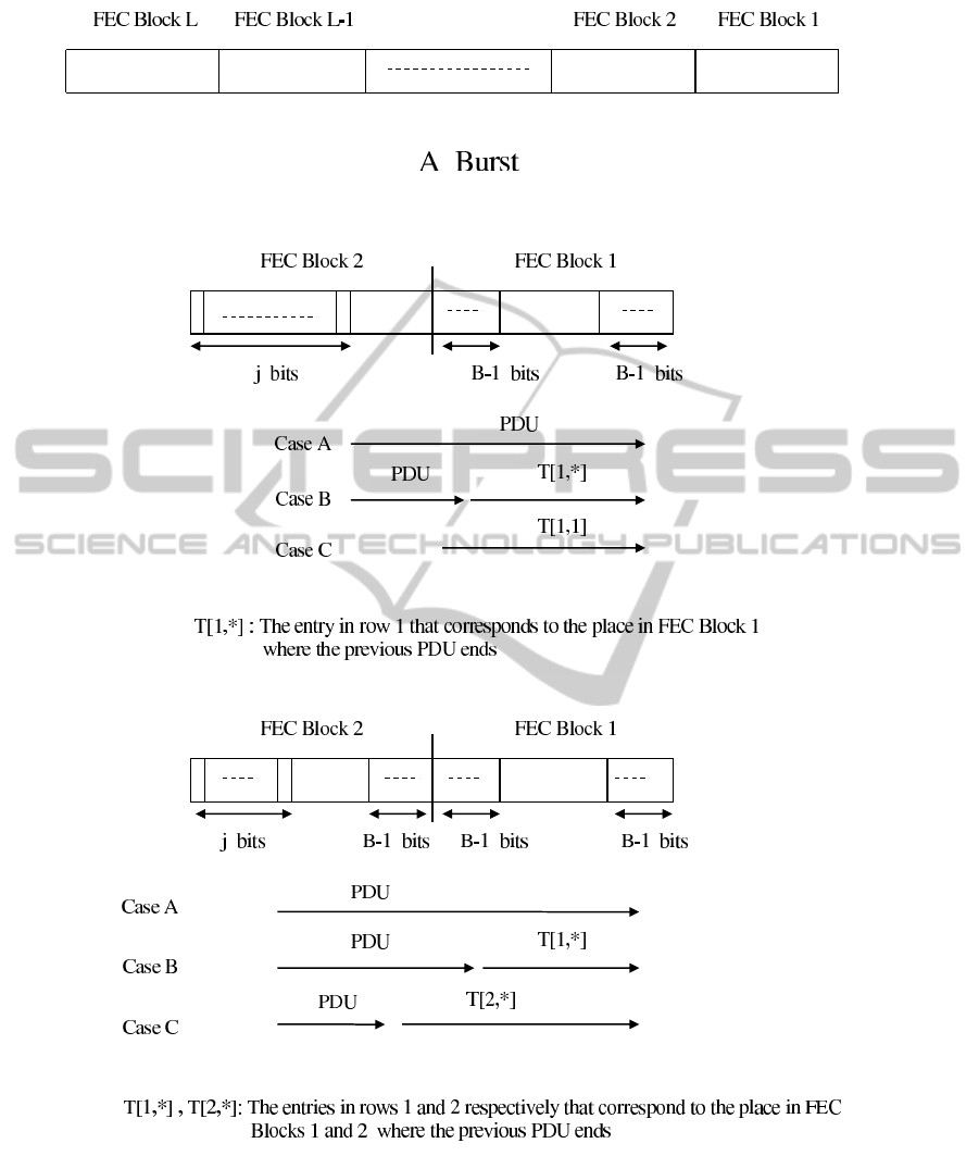
Figure 1: Numbering the FEC Blocks in a Burst.
Figure 2: Computing entry T [2, j],F − (B − 2) ≤ j ≤ F in the table of algorithm Division-Find.
Figure 3: Compuing entry T [2, j],1 ≤ j ≤ B in the table of algorithm Division-Find.
EfficientCoupledPHYandMACuseofPhysicalBurstsbyARQ-EnabledConnectionsinIEEE802.16e/WiMAX
Networks
195

Lemma 1. The value of every entry in row k of T ,
2 ≤ k ≤ L − 1, is computed in O(k)
Proof. Consider an entry T [k, j],F − (B−2) ≤ j ≤ F.
In order to compute this entry one needs to consider
two possibilities. The first one corresponds to the case
that the next PDU begins at the start of FEC Block
number k − 1. This case has the value T [1,k − 1]. The
other possibility corresponds to the case where a PDU
begins at bit j of FEC Block k. This PDU can end,
according to Theorem 2, at 2(k − 1) different Starting
and Ending edges. Thus, we need to choose the max-
imum among 2(k − 1) + 1 = 2k − 1 cases, where each
case is computed in O(1), possibly using entries from
previous rows.
Considering an entry T [k, j],1 ≤ j ≤ B, the argu-
ments are similar to the case above.
Theorem 3. The time complexity of Division-Find is
O(L
2
B).
Proof. First consider the computation of the entries
in row k, 2 ≤ k ≤ L − 1. In such a row there are 2B − 1
entries and each one is computed in O(k)(Lemma 1).
Thus, row k is computed in O(B · k). Summing over
all the rows k we get that their entries are computed
in O(L
2
B). In row 1 we compute only B entries, each
in O(1), and in row L we compute entries T (L,1) and
T [1,O + X · B] (see above) in O(L). The Theorem fol-
lows.
2.4.1 The Case 2B − 1 ≥ F
Notice that if 2B − 1 ≥ F then a PDU can end at every
position within a FEC Block. Therefore, algorithm
Division-Find is changed to contain only F entries in
any row, and its time complexity is O(L
2
F).
Remark 1. It is sometimes possible to receive the
same optimal B-Goodput in a Burst in different divi-
sions, such that the divisions contain different num-
ber of Data Blocks. For example, for L = 2 FEC
Blocks, F = 480 bits, B = 45 bits, O = 45 bits and
p = 0.9 there are two divisions that yield the maxi-
mum B-Goodput. In one division there is one PDU
with 20 Data Blocks and in another division there
are 2 PDUs, each being defined over a separate FEC
Block, with 9 Data Blocks each. Our algorithm is im-
plemented to choose the division with the largest num-
ber of Data Blocks.
2.5 Modulation/Coding Scheme (MCS)
Selection
IEEE 802.16e/WiMAX enables the use of the fol-
lowing Modulation/Coding schemes (MCSs) (IEEE,
2005): QPSK-1/2, QPSK-3/4, 16QAM-1/2, 16QAM-
3/4, 64QAM-1/2, 64QAM-2/3, 64QAM-3/4 and
64QAM-5/6. 64QAM-1/2 is practically not used
and so we will not consider this scheme any fur-
ther (Alpert et al., 2010).
Recall that when a Burst is defined, actually it uses
slots in the Physical layer. In any MCS the set of
slots in a Burst is divided into groups such that any
group is a FEC Block. In every MCS it is possible to
define groups of slots of different sizes, resulting in
FEC Blocks of different sizes. Here we only consider
the largest FEC Blocks that are possible in the MCSs.
We denote by j the number of slots, in every MCS,
needed to define the largest FEC Block. We show the
value of j for every MCS in Table 1, together with
F, the number of bits that the largest FEC Block con-
tains. We also show the success probability p of the
largest FEC Block in every MCS and in several values
of the SNR (Signal-to-Noise-Ratio). An entry with ∗
stands for N/A, which means that the success prob-
ability of a FEC Block in the considered MCS and
SNR is 0 . These probabilities are taken from (Jum,
2010). The input from (Jum, 2010) contains graphs
that address, for every MCS allowed in WiMAX, and
for many realistic SNR values, the success probabil-
ity for all possible length FEC Blocks in the consid-
ered MCS. We see from Table 1 that for low SNRs
(bad channels) only few MCSs are applicable, while
in high SNRs all the MCSs are applicable.
We also see that there is a trade-off in using the set
of slots of a Burst. On one hand it is possible to decide
on a reliable MCS to be used in the Burst. However,
the number of FEC Blocks, and so the number of bits
in the Burst, is low. On the other hand, a less reli-
able MCS results in more FEC Blocks and bits in the
Burst, but with a smaller success probability of the
FEC Blocks.
2.6 Performance Results
One criteria to decide on the best MCS is the B-
Goodput. In Table 2 we show the B-Goodput for ev-
ery MCS in every SNR value between 2 to 12 dB, for
the case of S = 900 slots, B = 128 bits and O = 104
bits. B = 128 bits is the smallest Data Block size
that is possible in IEEE 802.16e (IEEE, 2005). With
O = 104 bits we assume that a PDU contains the
GMH and the CRC fields of 6 and 4 bytes respec-
tively as overhead, and one Fragmentation SubHeader
(FSH) of 3 bytes, which is used when a PDU contains
Data Blocks (IEEE, 2005). The results in Table 2 are
received by using algorithm Division-Find. Accord-
ing to the B-Goodput criteria QPSK-1/2 can be cho-
sen as the best MCS to use in every SNR. However,
WINSYS2013-InternationalConferenceonWirelessInformationNetworksandSystems
196

Table 1: The number of slots j, the number of data bits F and the success probability p in various SNR values of the largest
FEC Block in various MCSs.
MCS j F SNR
2 2.5 3 3.5 4 4.5 5 5.5 6
QPSK 1/2 10 480 0.998 0.999 0.999 0.999 0.999 0.999 0.999 0.999 0.999
QPSK 3/4 6 432 0.38 0.85 0.96 0.998 0.999 0.999 0.999 0.999 0.999
16QAM-1/2 5 480 * * 0.43 0.82 0.976 0.998 0.999 0.999 0.999
16QAM-3/4 3 432 * * * * * * 0.42 0.79 0.957
64QAM-2/3 2 384 * * * * * * * * *
64QAM-3/4 2 432 * * * * * * * * *
64QAM-5/6 2 480 * * * * * * * * *
MCS SNR
6.5 7 7.5 8 8.5 9 9.5 10 10.5 11 11.5 12
QPSK 1/2 0.999 0.999 0.999 0.999 0.999 0.999 0.999 0.999 0.999 0.999 0.999 0.999
QPSK 3/4 0.999 0.999 0.999 0.999 0.999 0.999 0.999 0.999 0.999 0.999 0.999 0.999
16QAM-1/2 0.999 0.999 0.999 0.999 0.999 0.999 0.999 0.999 0.999 0.999 0.999 0.999
16QAM-3/4 0.995 0.999 0.999 0.999 0.999 0.999 0.999 0.999 0.999 0.999 0.999 0.999
64QAM-2/3 * * * 0.56 0.79 0.941 0.991 0.999 0.999 0.999 0.999 0.999
64QAM-3/4 * * * 0.33 0.46 0.73 0.92 0.990 0.999 0.999 0.999 0.999
64QAM-5/6 * * * * * 0.3 0.41 0.45 0.8 0.959 0.994 0.999
Table 2: The number of slots j, the number of data bits F and the B-Goodput in various MCSs and SNR values, for the case
S = 900 slots, B = 128 bits and O = 104 bits.
MCS j F SNR
2 2.5 3 3.5 4 4.5 5 5.5 6
QPSK 1/2 10 480 0.957 0.969 0.969 0.969 0.969 0.969 0.969 0.969 0.969
QPSK 3/4 6 432 0.225 0.589 0.791 0.955 0.969 0.969 0.969 0.969 0.969
16QAM-1/2 5 480 * * 0.254 0.548 0.847 0.957 0.970 0.970 0.970
16QAM-3/4 3 432 * * * * * * 0.249 0.511 0.781
64QAM-2/3 2 384 * * * * * * * * *
64QAM-3/4 2 432 * * * * * * * * *
64QAM-5/6 2 480 * * * * * * * * *
MCS SNR
6.5 7 7.5 8 8.5 9 9.5 10 10.5 11 11.5 12
QPSK 1/2 0.969 0.969 0.969 0.969 0.969 0.969 0.969 0.969 0.969 0.969 0.969 0.969
QPSK 3/4 0.969 0.969 0.969 0.969 0.969 0.969 0.969 0.969 0.969 0.969 0.969 0.969
16QAM-1/2 0.970 0.970 0.970 0.970 0.970 0.970 0.970 0.970 0.970 0.970 0.970 0.970
16QAM-3/4 0.969 0.969 0.969 0.969 0.969 0.969 0.969 0.969 0.969 0.969 0.969 0.969
64QAM-2/3 * * * 0.373 0.527 0.741 0.897 0.967 0.967 0.967 0.967 0.967
64QAM-3/4 * * * 0.196 0.273 0.453 0.911 0.920 0.969 0.969 0.969 0.969
64QAM-5/6 * * * * * 0.172 0.241 0.267 0.519 0.800 0.925 0.970
Table 3: The number of slots j, the number of data bits F and the average integral number of successfully transmitted Data
Blocks in various MCSs and SNR values, for the case S = 900 slots, B = 128 bits and O = 104 bits.
MCS j F SNR
2 2.5 3 3.5 4 4.5 5 5.5 6
QPSK 1/2 10 480 323 327 327 327 327 327 327 327 327
QPSK 3/4 6 432 114 298 400 483 490 490 490 490 490
16QAM-1/2 5 480 * * 172 370 572 646 655 655 655
16QAM-3/4 3 432 * * * * * * 252 517 790
64QAM-2/3 2 384 * * * * * * * * *
64QAM-3/4 2 432 * * * * * * * * *
64QAM-5/6 2 480 * * * * * * * * *
MCS SNR
6.5 7 7.5 8 8.5 9 9.5 10 10.5 11 11.5 12
QPSK 1/2 327 327 327 327 327 327 327 327 327 327 327 327
QPSK 3/4 490 490 490 490 490 490 490 490 490 490 490 490
16QAM-1/2 655 655 655 655 655 655 655 655 655 655 655 655
16QAM-3/4 981 981 981 981 981 981 981 981 981 981 981 981
64QAM-2/3 * * * 503 711 1000 1210 1305 1305 1305 1305 1305
64QAM-3/4 * * * 297 414 687 1383 1410 1471 1471 1471 1471
64QAM-5/6 * * * * * 290 406 451 875 1350 1560 1636
in QPSK-1/2 the Burst contains only 90 FEC Blocks
of 480 bits each. On the other hand, 64QAM-5/6 con-
tains 450 FEC Blocks of 480 bits each. This enables
the transmission of more bits in the Burst, although
with a reduced success probability.
Therefore, in Table 3 we show the average number
of Data Blocks that are transmitted successfully in the
Burst, again for every MCS in every SNR. The results
in Table 3 are received again by algorithm Division-
Find. This time we divide the number of successfully
transmitted Data bits by a Data Block size. Accord-
ing to this criteria, the best MCS can change from one
SNR to another. As the channel becomes better, i.e.,
higher SNR values, the MCS that enables to trans-
mit a larger number of bits in a Burst is becoming
the best MCS to use. For example, in SNR=12 dB
the best MCS is 64QAM-5/6 because the B-Goodput
of all the MCSs are about the same, but 64QAM-5/6
enables the largest number of bits in the Burst. For
SNR= 9 dB , 64QAM-2/3 enables to transmit suc-
EfficientCoupledPHYandMACuseofPhysicalBurstsbyARQ-EnabledConnectionsinIEEE802.16e/WiMAX
Networks
197

cessfully the largest number of Data Blocks, although
its B-Goodput is only the 5
th
in size. The larger num-
ber of bits in a Burst with 64QAM-2/3 enables to
compensate for the lower B-Goodput.
3 CONCLUSIONS
We suggest two performance criteria for the division
of a given Burst into PDUs that contain Data Blocks.
The first criteria measures the relation between the
number of successfully transmitted Data bits to the
Burst size. The second criteria measures the abso-
lute number of successfully transmitted Data bits in
the Burst. The two criteria lead to different choices
of the optimal MACS to use in the Burst, given an
SNR. From the user perspective it seams that the sec-
ond criteria is more important. In this case, as a rule
of thumb, the best MCS in a given SNR is one of the
two MCSs that enable to transmit the largest number
of Data Blocks in the Burst.
REFERENCES
Alpert, Y., Segev, J., and Sharon, O. (2010). Advanced cou-
pled phy and mac scheduling in ieee 802.16 wimax
systems. Physical Communication, 3:287–298.
Alpert, Y., Segev, J., and Sharon, O. (2013). Towards an
optimal transmission of sdus by msc in ieee 802.16
wimax systems.
Huang, F. H. (1997). Evaluation of soft output decoding
for turbo codes. Master’s thesis, EE Faculty, Virginia
Polytechnic Institute. http://scholar.lib.vt.edu/theses/
available/edit-71897-15815/unrestricted.
IEEE (2005). IEEE 802.16e, Part 16: Air Interface for
Fixed and Mobile Broadband Wireless Access Sys-
tems. IEEE Standards for Local and Metroplitan Area
Networks.
Jum, X. (2010). ZTE Corporation, China, Personal Com-
munication.
WiMAX (2008). Wimax forumtm mobile radio confor-
mance tests (mrct), release 1.0. Approved Specifica-
tion ( Revision 2.2.0 ).
WINSYS2013-InternationalConferenceonWirelessInformationNetworksandSystems
198
