
Light Scattering Device for Measuring Finest Particles
in the Exhaust of Diesel Engines
Harald Axmann
1
and Bernd Eichberger
2
1
AVL DiTEST Fahrzeugdiagnose GmbH, Alte Poststraße 152, 8020 Graz, Austria
2
Institute of Electronics, University of Technology, Inffeldgasse 12, 8010 Graz, Austria
Keywords:
Light Scattering, Periodical Technical Inspection, Diesel Engine, Particle Emissions.
Abstract:
Recent developments in engine technologies and exhaust aftertreatment systems significantly reduced the par-
ticle emissions of diesel engines. This also demands new measurement devices for the periodical emission
checks, which shall ensure unchanged low emissions over the vehicles’ lifetime. As the current light transmis-
sion technique has reached its detection limit, a new device based on light scattering is presented. This paper
gives a short overview of scattering theory, followed by a description of the measurement system. An emphasis
is placed on the control mechanism for achieving a stable light source. Furthermore first measurement results
are presented. Finally the issue of correlation between scattering and established measures is discussed.
1 INTRODUCTION
Particle emissions of internal-combustion engines are
a severe problem for health and environment (Mol-
lenhauer and Tsch¨oke, 2007; Nickel et al., 2013; Ris-
tovski et al., 2012). Just recently a study of the World
Health Organization found diesel soot to be cancero-
genic (IARC, World Health Organization, 2012). In
road traffic, particles are mainly produced by diesel
engines due to incomplete combustion. Many gov-
ernments have reacted by introducing limits for the
allowed exhaust emissions of newly built vehicles. In
Europe these are the European Emission Standards,
which have been tightened repeatedly since their cre-
ation in 1992. In other countries like Japan or the
USA similar regulations have been established (Mol-
lenhauer and Tsch¨oke, 2007). To fulfill the require-
ments new motor technologies and above all com-
pletely new aftertreatment systems like the diesel
particle filter (DPF) have been developed (Mamakos
et al., 2013; Swanson et al., 2013).
To ensure the compliance of the vehicles with
those limits over their lifetime they have to undergo
periodic emission checks. In the European Union
these are regulated by the directive 2010/48/EU (Eu-
ropean Commission, 2010). As an indication of the
particle emissions the opacity of the exhaust fumes
at free acceleration of the engine to cut-off speed is
used. The according measurement device is the opac-
ity meter, which measures the turbidity by means of
light transmission. For old diesel vehicles, known to
emit black clouds of soot, this method was by far sat-
isfactory. Modern vehicle generations have exhaust
gases which are effectively invisible, so this tech-
nique reaches its detection limit (Giechaskiel et al.,
2013). Due to the poor resolution of the device and
the wide measurement tolerances, the limits at the pe-
riodic emission checks cannot be tightened. Elevated
emissions resulting from damaged DPFs are not de-
tected with the current measurement device, or the
cars still pass the check, because the limits are too
loose (Boulter et al., 2011; German Association of
manufacturers and importers of Automobile Service
Equipment, 2010; VdT
¨
UV and DEKRA, 2010).
Consequently new devices for measuring the par-
ticle emissions in garages and vehicle inspection in-
stitutions are necessary. While providing the neces-
sary sensitivity they also need to fulfill the require-
ments for the usage in the garages. These are for
example simple operation and maintenance, mobility
and robustness. In a comparison of different meth-
ods for particle measurement another optical princi-
ple showed up as most promising: light scattering.
Instead of quantifying the attenuation of the transmit-
ted light the portion scattered into a distinct direction
is measured (see figure 1). By use of optimized sig-
nal processing this method can achieve a sensitivity
which surpasses that of opacity meters by two orders
of magnitude. The theory behind light scattering shall
be explained briefly in the following chapter.
457
Axmann H. and Eichberger B..
Light Scattering Device for Measuring Finest Particles in the Exhaust of Diesel Engines.
DOI: 10.5220/0004490704570462
In Proceedings of the 10th International Conference on Informatics in Control, Automation and Robotics (ICINCO-2013), pages 457-462
ISBN: 978-989-8565-70-9
Copyright
c
2013 SCITEPRESS (Science and Technology Publications, Lda.)
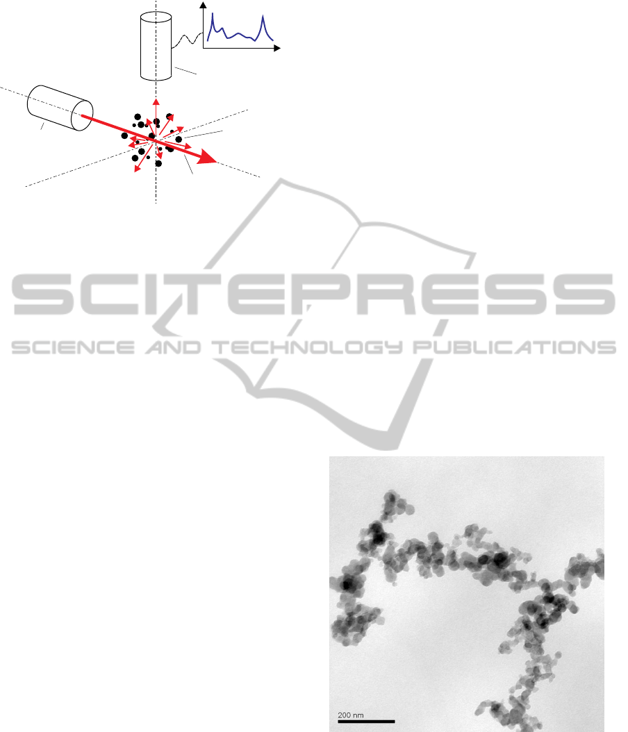
Light source
Incident
light beam
Particles
Scattered
light
Detector
Figure 1: Light scattering principle.
2 LIGHT SCATTERING THEORY
Light scattering is the deflection of light rays due to
heterogeneities in the lit medium. The first models for
describing the effect of light scattering go back to the
19
th
century. The simplest of these models was de-
veloped by Lord Rayleigh and deals with very small
particles compared to the wavelength of the incident
light. This so called Rayleigh scattering produces the
blue color of the sky (Bohren and Huffman, 1998;
van de Hulst, 1981). For such small particles the scat-
tered light only depends on their size in relation to
the wavelength, the polarization, the scattering angle
and the optical properties (the scattering index) of the
particle. The shape of the particles does not play any
role here. The upper limit for the application of the
Rayleigh model is reached for particle sizes between
one sixth and one tenth of the wavelength.
For bigger particles the shape has an influence on
the scattering behavior, too. For the simplest geo-
metric object, the sphere, a complete description of
the scattering properties was found in 1908 by Gus-
tav Mie (Mie, 1908). The mathematic functions used
herein are by far more complex than the Rayleigh for-
mulas and cannot be calculated in closed form. For
small particles both give the same results. Further
mathematical models exist for some selected geomet-
ric objects like cubes or cylinders, for which the ori-
entation adds as a variable.
For an ensemble of particles with arbitrary shape
a point is reached, where exact calculations become
too complex and therefore impractical. As the par-
ticles are typically randomly oriented, the approach
via approximation by spheres can be found in the lit-
erature (G¨orner et al., 1995; Hull et al., 2004). For
a random distribution of the particles in space, inter-
ference can be neglected and the total scattering can
be calculated as the sum of scattering from spherical
objects with adequate equivalent diameters. However
the shape of soot particles differs considerably from
spheres. They are chain-like aggregates of almost
spherical monomers, the so-called primary particles
(see figure 2). Hence the approximation via spheres
must be regarded critically. Although there are meth-
ods to exactly calculate the scattering of such aggre-
gates with known structure, this becomes impossible
for many particles with various structures and orien-
tations (Chakrabarty et al., 2007). Forrest and Witten
found a simpler mathematical description using frac-
tal theory based on the work of Mandelbrot (Forrest
and Witten, 1979). The scattering of these fractal-like
aggregates has been investigated by Sorensen in ex-
tensive studies (Sorensen, 2001). The following cen-
tral equation relates the number of primary particles
N to the geometric aggregate size R
g
:
N = k
0
(R
g
/a)
D
f
(1)
R
g
is a root-mean-square radius called radius of
gyration, a is the radius of the primary particles, k
0
a proportionality constant in the order of 1 and D
f
the fractal dimension. The latter is a measure of the
space filling capacity of objects. Small values mean
sparse long chains, whereas values near 3 mean dense
sphere-like structures. Soot particles typically have
D
f
≈ 1.78 or D
f
≈ 1.95, depending on the creation
process (Lapuerta et al., 2006).
Figure 2: Soot particle from a propane flame under a trans-
mission electron microscope (Reinisch, 2009).
On the basis of equation (1) a structure factor can
be calculated for the particle, which describes the in-
terference between the scattering contributions of the
primary particles. It is assumed that all monomers
are of the same size and see the same incident light
wave. Then the total scattering is the sum of the N
ICINCO2013-10thInternationalConferenceonInformaticsinControl,AutomationandRobotics
458
single scattering contributions of the monomers mul-
tiplied by the structure factor. The scattered light of
an ensemble of particles can again be calculated by
summation, because of the random distribution of the
particles.
2
4
6
8 × 10
−17
30
◦
210
◦
60
◦
240
◦
90
◦
270
◦
120
◦
150
◦
330
◦
180
◦
0
◦
Mie
Rayleigh
Fractal
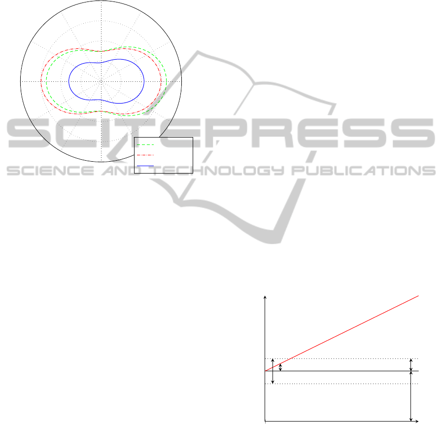
Figure 3: Calculated scattering intensity for a 100nm parti-
cle using various mathematical models.
Figure 3 shows the radial scattering intensity in
W/(m
2
sr) of a typical soot aggregate from combus-
tion processes using different mathematical models.
The size of the particle (diameter or 2R
g
respectively)
is 100 nm, its complex scattering index is assumed
as 1.5 + 1i. The incident light ray with wavelength
660 nm and an irradiance of 1W/m
2
is directed along
the positive abscissa. In the diagram one can nicely
see the starting deviation of the scattering between
Rayleigh and Mie model. For this size there is just a
little bit more forward scattering (i.e. in direction of
0
◦
). Forward scattering will become more and more
dominant for bigger particles. Furthermore ripples
from interferences appear. In comparison the scatter-
ing intensity of the fractal is smaller by two thirds,
because it is practically just the sum of the dispropor-
tionately weaker scattering of all the small primary
particles. In contrast to the Mie model there are no
ripples for any particle size. This is due to the fact that
the fractal model is based on the mean of the various
possible structures and orientations of a fractal-like
aggregate with the given parameters.
3 TECHNICAL REALISATION
Light scattering devices are used in non-exhaust re-
lated applications, e.g. for air quality monitoring
and for basic research (G¨orner et al., 1995; Hull
et al., 2004). However, for the use in the periodic
technical inspection special requirements have to be
fulfilled. These are robustness, resistance against
the sometimes tough environmental conditions in the
garages (temperature, humidity), mobility, high dy-
namic range (suitable for both low and high emitters),
low maintenance, short preparation time (e.g. heat-
ing up), compatibility with currently used measuring
units and finally low costs, to be affordable for the
garages.
Light scattering has an essential disadvantage:
The intensity of the scattered light is very small com-
pared to the incident intensity. Even if a wide angle
area is covered the ratio can be 1: 10
9
or more. Hence
strong light sources combined with sensitive detec-
tors are necessary to achieve the desired resolution.
Such components, especially strong lasers, are typi-
cally rather expensive. In comparison to light from
other sources laser light has the advantage to be very
well focusable, which is helpful for reducing the stray
light. Theoretically in light scattering the sensitivity
only depends on the absolute intensity of the incident
light, as there should ideally be no scattered light in
the absence of particles. In practice stray light and
reflections from the interior of the measurement cell
will produce some background light. That means that
the stability of the light source will directly influence
the lower detection limit, too. Noise or drift of the
light intensity degrade the performance considerably,
and increasing the intensity does not have a positive
effect (see figure 4). Therefore the control of the light
source is a crucial issue.
Sum of scattered
and background light
BG light
BG noise/drift
Detection limit
Real detection limit
due to source light
drift and noise
0
0
Particle concentration [a. u.]
Detector signal [a. u.]
Figure 4: Degraded detection limit due to noise and drift of
the background (BG) light in arbitrary units (a.u.).
For diode lasers the intensity is controlled via the
current through the diode. There are two principle
ways to operate them (Webb and Jones, 2004):
1. Automatic Current Control (ACC) operates the
diode with a constant current which is known to
LightScatteringDeviceforMeasuringFinestParticlesintheExhaustofDieselEngines
459
provide the desired intensity.
2. Automatic Power Control (APC) uses a monitor
diode to measure the laser optical output power
and to adjust the current accordingly.
APC is a simple solution to produce a more or less
constant intensity, which is ideally independent of the
ambient temperature. However depending on the cur-
rent and the temperature mode hopping may occur.
Mode hopping is the abrupt switching from one lon-
gitudinal mode in the laser to another (Heumier and
Carlsten, 1993; Pralgauskait˙a et al., 2013). It leads
to a small change in wavelength and intensity and can
even cause variationsin the direction of the laser light.
Best stability can be achieved with ACC and precise
temperature control. Though, for a bad combination
of case temperature and current, mode hopping may
still occur (Ascente, 2007). Furthermore precise tem-
perature stabilization is costly, so one might not want
to integrate it into a garage device.
Laser diode
I U R= /
CTL S
R
S
U
CTL
V
+
Figure 5: Simplified analog ACC control loop without sta-
bility measures.
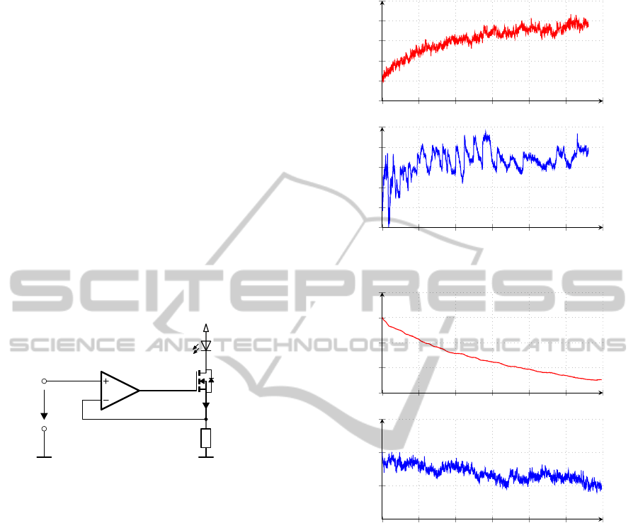
Several test runs showed that the best results in
terms of background light stability can be achieved
when using ACC with a constant average current and
an AC modulation superimposed (see figure 6). A fre-
quency of a few MHz and a modulation amplitude of
50 % are a good choice. Due to warming of the laser
diode in continuous operation the laser intensity de-
creases with constant current. This leads to a smaller
scattering signal and a drop in the signal background
and has to be corrected by postprocessing. The ef-
fective laser power can be determined via the moni-
tor diode. This information can be used in the micro
processor to correct both the scattering and the back-
ground signal accordingly. As the stray light might
not be directly proportional to the intensity in the fo-
cus, zero correction might not work optimally. Still
sufficiently stable background light levels could be
achieved.
For the actual system red diode lasers with a wave-
length of 660 nm and optical powers of 5-15mW
are used. The wavelength is relatively big in com-
parison to the exhaust particles. The accumulation
mode, which contains most of the particle mass, has
0 5 10 15 20 25 30
−2
0
2
4
6
8
·10
−3
Laser power P
L
[%]
0 5 10 15 20 25 30
−1
0
1
2
3
4
Time t [min]
Background V
B
[%]
(a)
0 5 10 15 20 25 30
−3
−2
−1
0
1
Laser power P
L
[%]
0 5 10 15 20 25 30
−2
−1
0
1
Time t [min]
Background V
B
[%]
(b)
Figure 6: Normalized laser power and background signal
in the measurement cell for different laser operation modes
without temperature control. (a) APC: The laser power is
held almost perfectly constant, the background signal shows
drift and spontaneous changes due to mode hopping though.
(b) ACC with modulation: The background signal is much
smoother and its drift is very small.
its peak around 100 nm (Kittelson, 1998; Liu et al.,
2012). This is already near the Rayleigh limit at
this wavelength. For particles below this size limit
scattering will decrease with the sixth power of the
size, quickly reaching the detection limit. Lasers
with shorter wavelength are still very expensive. The
gain in scattering is furthermore partly suspended by
the low spectral efficiency of photo diodes for these
wavelengths. Since the soot particles have a very
broad size distribution there are still many particles
that can be nicely detected using red light.
ICINCO2013-10thInternationalConferenceonInformaticsinControl,AutomationandRobotics
460
For detection a small photodiode with 1mm
2
of
sensitive area is used. It is thermally isolated from the
measurement cell to reduce temperature influences.
The current generated by the photo diode is in the pi-
coampere range and below. It is amplified in a sophis-
ticated circuit using special shielding measures to re-
duce electromagnetic interferences. Precision analog
digital converters typically feature a differential input
structure. The single ended current signal of the diode
is converted to such a differential voltage as exactly
as possible. For this purpose a new amplifier circuit
design is used (Axmann and Eichberger, 2012, Euro-
pean patent pending). The photo diode is connectedto
two symmetric transimpedance amplifiers leading to a
differential signal around a center voltage. Noise on
the supply line will merely influence this center volt-
age resulting in a common mode interference, which
is suppressed by the analog digital converter.
In combination with a high amplification over-
sampling is used to achieve a higher resolution. The
analog signal is sampled at a rate of 1 MHz, whereas
the data output rate is 100 Hz. Test measurements
confirmed that this temporal resolution is sufficient to
completely trace the exhaust emissions of combustion
engines. It is noteworthy that in the measurement cir-
cuit a dynamic range of 120dB is attained with only
one amplifier stage. The lowest measurable currents
are approximately 250fA, which is equivalent to ap-
proximately 500 fW of optical power.
4 CORRELATION TO
ESTABLISHED MEASURES
Measurements confirmed that the new device is com-
parable to much more expensivetest bench equipment
in terms of sensitivity. Thus it is capable of reliably
detecting smallest defects in the DPF. However, for
type approval of the new measurement technique a
conversion of the scattering signal to established mea-
sures is necessary. For Germany this is the opacity
N in percent or the equivalent absorption coefficient
k in 1/m. Such a conversion is not straight forward,
because there is no direct physical relation between
scattering and opacity. A look at the mathematic for-
mulas illustrates that properties like used wavelength
or shape, size and optical properties of the particles
have an essential impact on the result.
Moreover the measurement principles differ in
their sensitivities. For example light transmission is
notably sensitive to NO
2
. This is a brown gaseous
exhaust component, which also attenuates the inci-
dent light (Giechaskiel et al., 2013; Mollenhauer and
Tsch¨oke, 2007; Norris, 2005). A series of measure-
ments at DPF equipped vehicles revealed that opac-
ity from NO
2
can even be the major part. For light
scattering there is no such influence because the gas
molecules are below the detection limit. Accordingly
light scattering is a pure particle measurement tech-
nique. With this in mind a conversion of the scatter-
ing signal to a particle mass concentration in mg/m
3
seems reasonable. Photo acoustic soot sensors have
proven to be a good reference for real time measure-
ments of the mass concentration. They are based
on the resonant measurement of acoustic waves cre-
ated by periodically absorbing particles. The mea-
sured signal is proportional to the soot mass concen-
tration with minimal cross sensitivity (Mollenhauer
and Tsch¨oke, 2007). The limitation to soot however
makes direct comparison to scattering signals some-
times difficult, e. g. when abrasion particles are in-
volved.
Those considerations lead to the conclusion that
a fundamental conversion of the scattering signal to
the said measures is impossible. Instead one has
to rely on empirical formulas. A series of studies,
e.g. (VdT
¨
UV and DEKRA, 2010), and measure-
ments demonstrated that there is a good overall com-
parability between scattering, opacity and mass con-
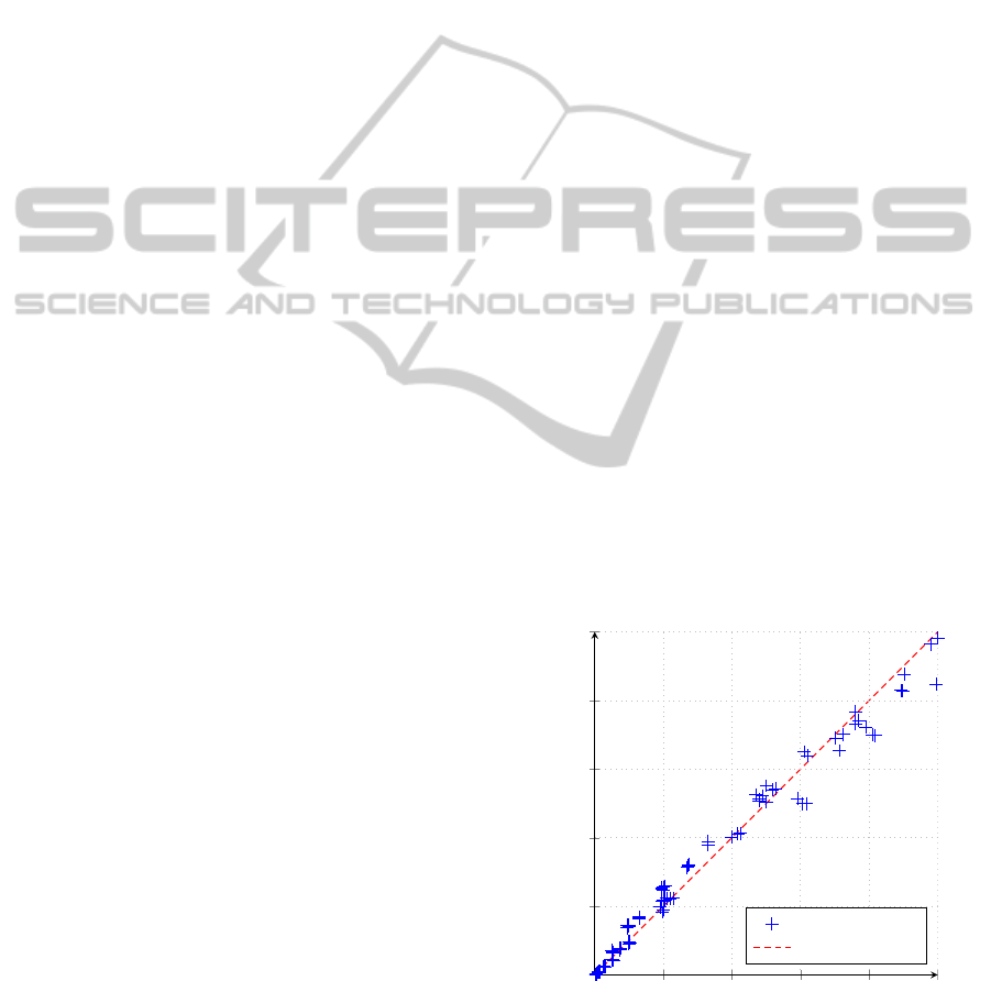
centration. In figure 7 the comparison of a device
based on scattering to an opacity meter for soot parti-
cles from propane combustion is shown. A good cor-
relation exists in the depicted range. Based on the
used conversion formulas the detection limit of light
scattering can be derived. It is below k = 0.0001/m.
This is an improvement of two orders of magnitude
compared to currently available garage opacity me-
ters (Norris, 2005).
0 0.2 0.4 0.6 0.8 1
0
0.2
0.4
0.6
0.8
1
Opacity meter: absorption k [1/m]
Light scattering: absorption k [1/m]
Measured data
Ideal
Figure 7: Correlation of the absorption coefficient between
an opacity meter and a light scattering device (k ≤ 1 /m).
LightScatteringDeviceforMeasuringFinestParticlesintheExhaustofDieselEngines
461

5 CONCLUSIONS
A particle measurement method for periodic emis-
sion tests based on light scattering has been presented.
Care must be taken that noise from the incident light
(e.g. due to mode hopping for laser sources) is min-
imized to achieve highest possible resolutions. In
combination with a sensitive detection system reso-
lutions 100 times better than that of current garage
opacity meters can be achieved at comparable costs.
The temporal resolution (100 Hz) is by far sufficient
for tracing exhaust emissions. Thus light scattering
devices are suitable for the exhaust measurement of
vehicles with state-of-the-art aftertreatment systems.
Further work will focus on the conversion of these re-
sults to established measures like opacity in order to
ensure the applicability of the determined formulas.
REFERENCES
Ascente, T. (2007). Laser diode intensity noise induced by
mode hopping. Rom. Rep. Phys., 59(1):87–92.
Axmann, H. and Eichberger, B. (2012). Circuit configura-
tion for evaluating photoelectric measurements. Euro-
pean Patent Application EP2501036A1.
Bohren, C. F. and Huffman, D. R. (1998). Absorption and
scattering of light by small particles. Wiley, New
York.
Boulter, P., Buekenhoudt, P., Stricker, P., et al. (2011). TED-
DIE – A new roadworthiness emission test for diesel
vehicles involving NO, NO
2
, and PM measurements.
Final report, CITA.
Chakrabarty, R. K., Moosm¨uller, H., Arnott, W. P., et al.
(2007). Light scattering and absorption by fractal-like
carbonaceous chain aggregates: comparison of theo-
ries and experiment. Appl. Optics, 46(28):6990–7006.
European Commission (2010). Commission Directive
2010/48/EU of 5 July 2010 adapting to technical
progress Directive 2009/40/EC of the European Par-
liament and of the Council on roadworthiness tests for
motor vehicles and their trailers. OJ L 173:42-72.
Forrest, S. R. and Witten, T. A. (1979). Long-range correla-
tions in smoke-particle aggregates. J. Phys. A: Math.
Gen., 12(5):L109–L117.
German Association of manufacturers and importers of Au-
tomobile Service Equipment (2010). Diesel-AU: Die
Endrohrpr¨ufung ist unerl¨asslich. Press Info. 4/10.
Giechaskiel, B., Schiefer, E., Schindler, W., Axmann, H.,
et al. (2013). Overview of soot emission measure-
ments instrumentation: From smoke and filter mass
to particle number. SAE Int. J. Engines, 6(1):10–22.
G¨orner, P., Bemer, D., and Fabri´es, J. (1995). Photometer
measurement of polydisperse aerosols. J. Aerosol Sci.,
26(8):1281–1302.
Heumier, T. A. and Carlsten, J. L. (1993). Detecting mode
hopping in semiconductor lasers by monitoring inten-
sity noise. IEEE J. Quantum Elect., 29(11):2756–
2761.
Hull, P., Shepherd, I., and Hunt, A. (2004). Modeling
light scattering from diesel soot particles. Appl. Opt.,
43(17):3433–3441.
IARC, World Health Organization (2012). Diesel engine
exhaust carcinogenic. Press Release No. 213.
Kittelson, D. B. (1998). Engines and nanoparticles: A re-
view. J. Aerosol Sci., 29(5/6):575–588.
Lapuerta, M., Ballesteros, R., and Martos, F. (2006). A
method to determine the fractal dimension of diesel
soot agglomerates. J. Colloid Interface Sci., 303:149–
158.
Liu, Z., Swanson, J., Kittelson, D. B., and Pui, D. Y. H.
(2012). Comparison of methods for online measure-
ment of diesel particulate matter. Environ. Sci. Tech-
nol., 46(11):6127–6133.
Mamakos, A., Martini, G., and Manfredi, U. (2013). As-
sessment of the legislated particle number measure-
ment procedure for a euro 5 and a euro 6 compliant
diesel passenger cars under regulated and unregulated
conditions. J. Aerosol Sci., 55:31–47.
Mie, G. (1908). Beitr¨age zur Optik tr¨uber Medien, speziell
kolloidaler Metall¨osungen. Ann. Phys., 25(3):377–
445.
Mollenhauer, K. and Tsch¨oke, H. (2007). Handbuch Diesel-
motoren. Springer, Berlin Heidelberg, 3
rd
edition.
Nickel, C., Kaminski, H., Hellack, B., Quass, U., et al.
(2013). Size resolved particle number emission fac-
tors of motorway traffic differentiated between heavy
and light duty vehicles. Aerosol. Air Qual. Res.,
13(2):450–461.
Norris, J. O. W. (2005). Low emission diesel research
CP17/18/770. Phase 3 – Report, Vehicle and Oper-
ator Services Agency (VOSA).
Pralgauskait˙a, S., Palenskis, V., Matukas, J., et al. (2013).
Analysis of mode-hopping effect in Fabry-P´erot
multiple-quantum well laser diodes via low frequency
noise investigation. Solid State Electron., 79:104–110.
Reinisch, T. (2009).
¨
Uber die Morphologie von Rußpar-
tikeln von Verbrennungskraftmotoren im Hinblick auf
Partikelanzahlmessung. Bachelor Thesis, Graz, Uni-
versity of Technology.
Ristovski, Z. D., Miljevic, B., Surawski, N. C., Morawska,
L., et al. (2012). Respiratory health effects of diesel
particulate matter. Respirology, 17(2):201–212.
Sorensen, C. (2001). Light scattering by fractal aggregates:
A review. Aerosol Sci. Technol., 35(2):648–687.
Swanson, J. J., Watts, W. F., Newman, R. A., et al. (2013).
Simultaneous reduction of particulate matter and NO
x
emissions using 4-way catalyzed filtration systems.
Environ. Sci. Technol., 47(9):4521–4527.
van de Hulst, H. C. (1981). Light scattering by small parti-
cles. Dover Publications, New York.
VdT
¨
UV and DEKRA (2010). Emission Check 2010 Teil 2
– Diesel.
Webb, C. E. and Jones, J. D. C., editors (2004). Hand-
book of Laser Technology and Applications, volume
I: Principles. Institute of Physics Publishing, Bristol,
Philadelphia.
ICINCO2013-10thInternationalConferenceonInformaticsinControl,AutomationandRobotics
462
