
QReal DSM Platform
An Environment for Creation of Specific Visual IDEs
Anastasiia Kuzenkova, Anna Deripaska, Timofey Bryksin, Yurii Litvinov and Vladimir Polyakov
Department of Software Engineering, Saint-Petersburg State University,
Universitetskii prospekt 28, Petrodvorets, St. Petersburg, Russian Federation
Keywords: Metamodeling, Visual Languages, DSL, Domain-Specific Modeling, DSM Platforms.
Abstract: This article describes a QReal technology designed for rapid creation of domain-specific languages
(“DSL”). Domain-specific modeling (“DSM”) is a promising paradigm which provides enhanced
development productivity (3 to 10 times in selected cases compared to common development
methodologies). This fact contributes to the interest in the DSM support tools. QReal is a research project
having an objective of creating a prototype of such a tool. Overview of QReal basic metamodeling
capabilities such as abstract and concrete syntax definition is provided in the article, as well as the
description of some advanced capabilities such as defining semantics of visual language, constraints and
refactoring support. Two cases of successful application of this technology to creating domain-specific
solutions are presented and future work directions are addressed.
1 INTRODUCTION
Visual modeling tools are widely used in software
engineering with several approaches existing to
develop software using visual modeling paradigm
(Briand et al., 2012); (Clark and Muller, 2012);
(Mohagheghi et al., 2013). Some of them are based
on predefined set(s) of visual languages that could
be applied to a wide range of software products
(general purpose languages). Others support domain
specific modeling (DSM) — an approach that
enables creation of custom languages aimed
specifically for the task being solved. These
languages capture key domain entities, abstractions
and relationships between them. According to
existing studies this approach sometimes proves to
be more effective than use of general-purpose
programming languages and tools in many domains.
An example is mobile applications development
where a program could be described by its screen
flow and appropriate API calls, or message
processing in communication software (Kelly and
Tolvanen, 2008). With an appropriate tool support
this approach can significantly increase the level of
abstraction which modellers are working at and thus
increase their productivity significantly (Kieburtz et
al., 1996).
Creating tool support from scratch for every
single domain-specific language (DSL) would be
prohibitively costly, thus there is a need to have
tools that simplify creation of tool support for DSLs,
so called DSM platforms. There exist several of such
tools, research and industrial: Microsoft Visual
Studio Visualization and Modeling SDK
1
, Eclipse
GMP
2
, MetaEdit+ (Kelly et al., 1996) and some
others (e.g. (Amyot et al., 2006); (Nytun et al.,
2006)). Our goal is to develop a DSM platform
which would be easy to study and use and which
could be used even in small scale projects.
The contribution of this article is a description of
implementation of a DSM platform which was
successfully used in several industrial projects. This
can add to an existing body of knowledge about
implementation techniques of such complex tools.
Described platform differentiates from other such
tools by being lightweight and easy to use, but still
having important functionality common to much
more complex tools in this field, like visual
metamodeling, model refactoring, model constraints
and semantics.
1
Visual Studio Visualization and Modeling SDK (was DSL
SDK), URL: http://archive.msdn.microsoft.com/vsvmsdk
2
Eclipse Graphical Modeling Project (GMP), URL:
http://www.eclipse.org/modeling/gmp/
205
Kuzenkova A., Deripaska A., Bryksin T., Litvinov Y. and Polyakov V..
QReal DSM platform - An Environment for Creation of Specific Visual IDEs.
DOI: 10.5220/0004505002050211
In Proceedings of the 8th International Conference on Evaluation of Novel Approaches to Software Engineering (ENASE-2013), pages 205-211
ISBN: 978-989-8565-62-4
Copyright
c
2013 SCITEPRESS (Science and Technology Publications, Lda.)

2 QReal: A DSM PLATFORM
QReal (Терехов et al., 2009) technology is being
developed by a research group at software
engineering department of St. Petersburg State
University, led by prof. A. Terekhov.
Originally QReal was expected to be a further
development of REAL (Терехов et al., 1999)
technology, extended by using UML 2.0 as main
modeling language. It was supposed to be multi-
platform (supporting a number of operating systems
including Linux and MS Windows) and multi-user
by design. The scope also included provisioning of
remote network access to the repository and other
features typical for modern visual modeling systems.
However it quickly became obvious that coding
a dozen of visual editors manually was producing a
huge overhead — first of all, it’s exhausting, and
moreover one gets an IDE that is considerably
difficult to maintain and scale. To deal with this we
developed metamodeling approach and respective
tools turning QReal into a DSM platform.
3 METAMODELING IN QReal
We define metamodel as a model of a modeling
language (Karagiannis and Kühn, 2002). In the
domain-specific paradigm metamodel is the main
source of knowledge about the language, its
properties and key features. Therefore, in DSM
platforms metamodels are central artifacts, a set of
tools supporting developed language is
automatically constructed based on metamodel of
this language.
Metamodels creation (called metamodeling) is
far from trivial, however there is a quite definite
process of constructing consistent metamodels,
which allows to divide this task into a number of
steps (that could be iteratively repeated if
necessary):
description of abstract syntax;
description of concrete syntax;
description of semantics; and
description of constraint rules set on models of
the elements.
Success of DSM solutions depends on many factors
— not just on how well the entities of domain are
captured in language constructs and how accurately
the metamodel describes them, but also how
expressive are the tools that DSM platform provides
to language developers and how feature rich are the
solutions that can be created using this platform.
The rest of the section describes how
aforementioned steps are supported in QReal.
3.1 Abstract Syntax
Abstract syntax defines language elements that are
used while modeling and relationships between
them. These descriptions are made using meta-
language, i.e. a language to define other languages.
In QReal all language abstractions are divided
into two categories — graphical and non-graphical.
Graphical entities are “element” and “relationship”,
an example of non-graphical entity could be
“enumeration”, which describes a set of values that
can be used as property values of an element. Also it
is possible to define generalizations between
elements and to describe that one element can be a
container for others, such relationships are depicted
on metamodel diagrams as links with arrows. It is
also possible to specify some additional properties
supported by QReal core engine, e.g. which links
can be connected to which elements or whether it is
needed to lay out child elements in a container or
not.
There are two ways to describe abstract syntax
for a language in QReal: textual and visual. In
textual approach metamodel is represented by an
XML file, in visual one metamodel is being
developed using meta-editor, a special visual editor
for meta-language. Textual and visual
representations of metamodel descriptions are
interchangeable — an XML file can be generated
from visual metamodel, and vice-versa XML file
can be parsed and visual metamodel can be created
based on it.
Along with meta-editor there is another tool
supported in QReal for meta-language purpose. Its
infrastructure supports a full language development
cycle: a developer can create a visual language,
compile it into a plug-in module and open it in
QReal without leaving the development
environment.
3.2 Concrete Syntax
Concrete syntax describes visual representation of a
modeling language. There are two major approaches
to define concrete syntax: static and dynamic
(Karagiannis and Kühn, 2002).
To support static approach QReal employs shape
editor to specify shapes of graphical elements. Shape
editor is a vector graphical editor, which has most of
typical graphical editors’ capabilities (tools to draw
geometric primitives and text labels, pen, etc.), and
ENASE2013-8thInternationalConferenceonEvaluationofNovelSoftwareApproachestoSoftwareEngineering
206

capabilities specific to shapes of visual language
elements (like ability to bind text labels to element’s
properties, or to specify resize policy for particular
parts of a shape). It also allows using existing image
files, which is very useful for DSL — as it allows
creating elements which resemble real world entities
they suppose to represent. It is very helpful for
domain experts who have little experience in
programming and even modeling — the language
becomes intuitive for them and raises readability of
visual programs.
To support dynamic approach QReal uses
widgets editor that allows to parameterize static
shapes with run-time information from repository —
for example, to add a text label showing element’s
name or a checkbox representing one of element’s
boolean properties’ value. Apart from mentioned
text and boolean values widgets editor also supports
combo boxes for enumerated property values and a
number of layouts to organize these widgets within
the shape of an element. While modeling using this
language one can use these widgets to change
property values directly on a diagram.
3.3 Constraints
For modeling tools it is important to minimize
possibility of constructing invalid models. Tool and
language developers should have means to define
semantic rules of target language, such as constraints
(i.e. some logical conditions which ensure
correctness of programs).
There are two major types of constraints:
constraints on run-time model state (e.g. assert
statements in generated code) and constraints on the
language itself (i.e. constraints on how models are
created using this language). The latter is supported
in QReal via defining constraints on models using
special visual language and checking these
constraints in run-time while modeling. This
mechanism works as follows. Language developer
creates constraints model, consisting of one or more
diagrams. Each diagram allows to define constraints
for exactly one visual language within this
metamodel. Constraint diagram is constructed of
simple constraints, for each such simple constraint
language developer should specify:
element type name or logical condition to select
a set of elements that the constraint will be
applied to; and
logical predicates that must be true for any
specified element at any time during modeling.
Logical predicates are defined graphically using
special elements of constraint language. After
constraints model on visual language is complete,
one can automatically generate appropriate tools that
check these constraints in run-time. These tools are
built in a plug-in module and are used by QReal core
engine. During modeling using target language
constraints checks are triggered by the following
events:
change of element name or property value;
change of container relationships;
creation and removal of items; and
reconnection of links.
If some constraints are not satisfied, QReal informs
the user about it. If constraint type was 'warning', the
element that violates the constraint is highlighted
red. If the type was 'critical', then in addition to
highlighting an error text message is shown in
special error window. This text is defined by
language developer while creating constraints model
and should describe the problem.
3.4 Semantics
All visual languages are divided into static ones
describing system structure and behavioural ones
describing interaction of system parts and other
behaviour dynamics. For behavioural languages in
order to organize visual interpretation and
debugging of models language execution semantics
must be specified.
Semantics definition approach implemented in
QReal is based on graph grammars and graph
transformation technology (Rozenberg, 1997);
(Hausmann, 2005). A model in any visual language
is considered as typed oriented multigraph with
attributes and inheritance and semantics is a set of
extended graph transformation rules.
Graph transformation rule consists of left hand
side and right hand side parts. Rules are evaluated
against an input graph called host graph. If a match
for the left hand side part is found for the host graph,
the rule can be applied. When a rule is applied, the
matching subgraph of the host graph is replaced by
the right hand side part of the rule (Lacoste-Julien et
al., 2004). Rule application might include creation,
removal or replacement of model elements. For
convenience, special elements in rules called node
unifiers can be used. Comparison of any node of
original model with a unifier node always succeeds.
Also, for clarity of perception each element has a
semantic status mark indicating whether to create,
delete, or save this element without changes.
An extension of graph transformation rules
includes ability to track model execution flow and to
QRealDSMplatform-AnEnvironmentforCreationofSpecificVisualIDEs
207
interpret rule application reaction code. Tracking of
model execution flow is implemented using a special
element and a link. Executed node is connected with
execution token and will be highlighted in model
while debugging.
However graph transformation rules don't allow
any calculations on element property values and
dynamic changes of them. This problem can be
solved by so-called rule application reactions.
Reaction to a rule application is a piece of code on
an interpreted language (currently QReal supports
Python and QtScript for rules reaction code) which
is executed immediately after the rule is applied but
before model elements removal (when it's
necessary). This mechanism is intended to be used to
manipulate property values of model elements and to
organize elements interaction in rule description. It
can also be used to create code generators — an
interpreter can generate custom output text while
executing the model.
3.5 Refactoring
Model refactoring is a process of model
transformation performed to gain better readability
or to automate operations on multiple model
elements. Usually model refactorings are defined by
transformation rules (created by language or tool
developer) which are later applied by modellers that
use DSM solutions.
Below is the description of how refactoring rules
definition and application mechanism are
implemented in QReal. Here refactorings are defined
on metamodel level, and are applied on model level.
Similar to semantics definition they are also based
on graph grammars and use QReal's graph search
and transformation mechanism. A special visual
language for definition of refactoring rules is used,
all elements of which are divided into two major
groups:
1. Refactoring definition pattern, consisting of
refactoring rules elements. They are left hand
side block, right hand side block and
transformation direction link. Left hand side
block contains pattern describing model
subgraph that will be changed, right hand side
block contains pattern describing model part that
will replace matched subgraph. Transformation
direction link is a link from a left hand side block
to a right hand side block, used for convenience
only.
2. Basic refactoring rule elements, including node
unifier, link unifier and selected segment
element. A node unifier matches any element of
a model, a link unifier matches any link of a
model, a selected segment element matches a
group of model elements, selected before
applying the rule.
Also, some refactoring rule definitions might include
elements of the target language (e.g. the refactoring
rule is associated with elements or links of certain
type). In this case the refactoring language will be
dynamically extended by elements from the target
language metamodel.
After refactoring rules are created, they should
be appropriately saved so when the user is modeling
using this language later these rules could be found
in the respective QReal dialog. This dialog lists all
refactoring rules available at the moment and allows
user to apply them — find subgraphs matching to
rules patterns and appropriately transform them.
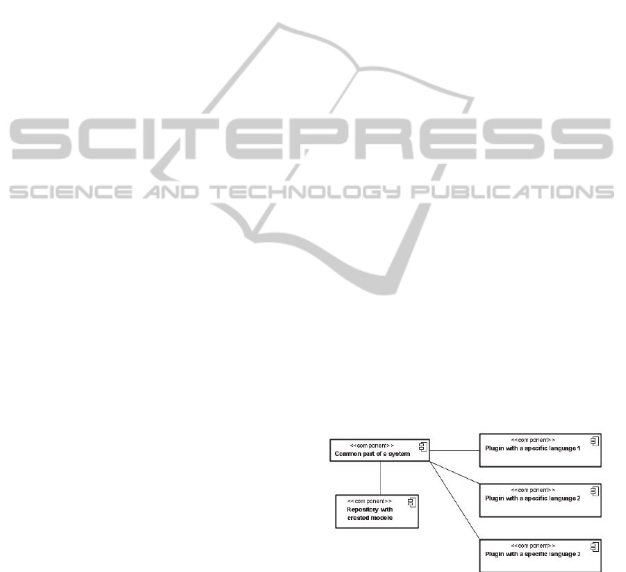
3.6 Metamodeling Architecture
The part of QReal architecture related to
metamodeling capabilities is shown on figure 1. All
information about languages syntax is stored in
plugins, as QReal core modules have no code related
to particular languages, working in the same way for
all of them. Created models are stored in a
repository, which also does not have any language-
specific information and is representing models in a
uniform way.
After creating abstract and concrete syntax,
semantics and other models mentioned above
language developer automatically creates several
dynamically linked modules using appropriate tools
of QReal platform. These modules are plugged into
the platform and provide all information about the
language and tools of created DSM solution.
Figure 1: QReal metamodeling architecture.
4 APPROBATION
There are several examples of DSLs created using
QReal platform, such as QReal:Ubiq, QReal:Robots
and some others.
ENASE2013-8thInternationalConferenceonEvaluationofNovelSoftwareApproachestoSoftwareEngineering
208
QReal:Ubiq is a domain-specific solution for
mobile applications development using Ubiq Mobile
framework (Onossovski and Terekhov, 2009). This
framework is also developed in St. Petersburg State
University and is designed as a platform that
provides a way to create cross-platform client-server
mobile applications with rich server functionality.
Every Ubiq Mobile program has a server part and a
client part; they have clearly defined structure,
which makes them good targets for automatic code
generation. A client part is basically a finite state
machine, and a server part is a reactive program that
can handle incoming requests and send back results.
The domain-specific solution for Ubiq Mobile
consists of three visual languages. First language is
used to describe data structures which are used
within a communication protocol between client and
server sides and is quite similar to UML class
diagrams. Second language is used to represent logic
of the client and server parts and is based on UML
activity diagrams. Each diagram in this language is a
handler of an incoming message for a server part, or
a diagram describing whole client logic. C# code is
used within blocks to provide required
implementation. Third language specifies what is
called “Master diagram” that binds all previously
described parts together by specifying server
message handlers, used data structures and links to
their implementations.
This DSM solution was implemented using
QReal, and it took about three days for two full time
developers to get a working prototype and to create
an example application using it. The application
transferred video stream from selected web-camera
on a server to a mobile phone. The solution was
presented on 10th FRUCT conference in Tampere,
Finland (Bryksin et al., 2011).
In this case we were able to quickly create a set
of visual editors and generators that provided clearly
seen benefits for Ubiq Mobile developers. Level of
abstraction was changed from C# classes to event
handlers drawn in “workflow” style, so developers
that use our solution might not know object-oriented
features of C# at all. According to one of the authors
of Ubiq Mobile platform even his eleven year old
daughter could write client-server applications for
mobile phones using these visual languages. But this
case also shows a major drawback of this style of
visual languages: handlers' logic was written using a
subset of C# directly in visual blocks, so the
developer still has to know at least basics of C#
programming and C# syntax. It seems to be
unavoidable, because if we try to use only visual
blocks to construct complex logic, diagrams will
become really huge and even more complex than
their textual representation.
QReal:Robots (Брыксин и Литвинов, 2011) is a
visual IDE for programming LEGO Mindstorms
NXT 2.0
3
robots. LEGO Mindstorms NXT 2.0 is a
robotic constructor which has three types of sensors,
three servo motors, a programmable control brick
and a number of plastic details and connectors. It
could be used as a visual representation for teaching
programming in schools. A robot can be
programmed using some textual and visual
languages, a program can be executed directly on a
robot, or a robot can be controlled by Bluetooth
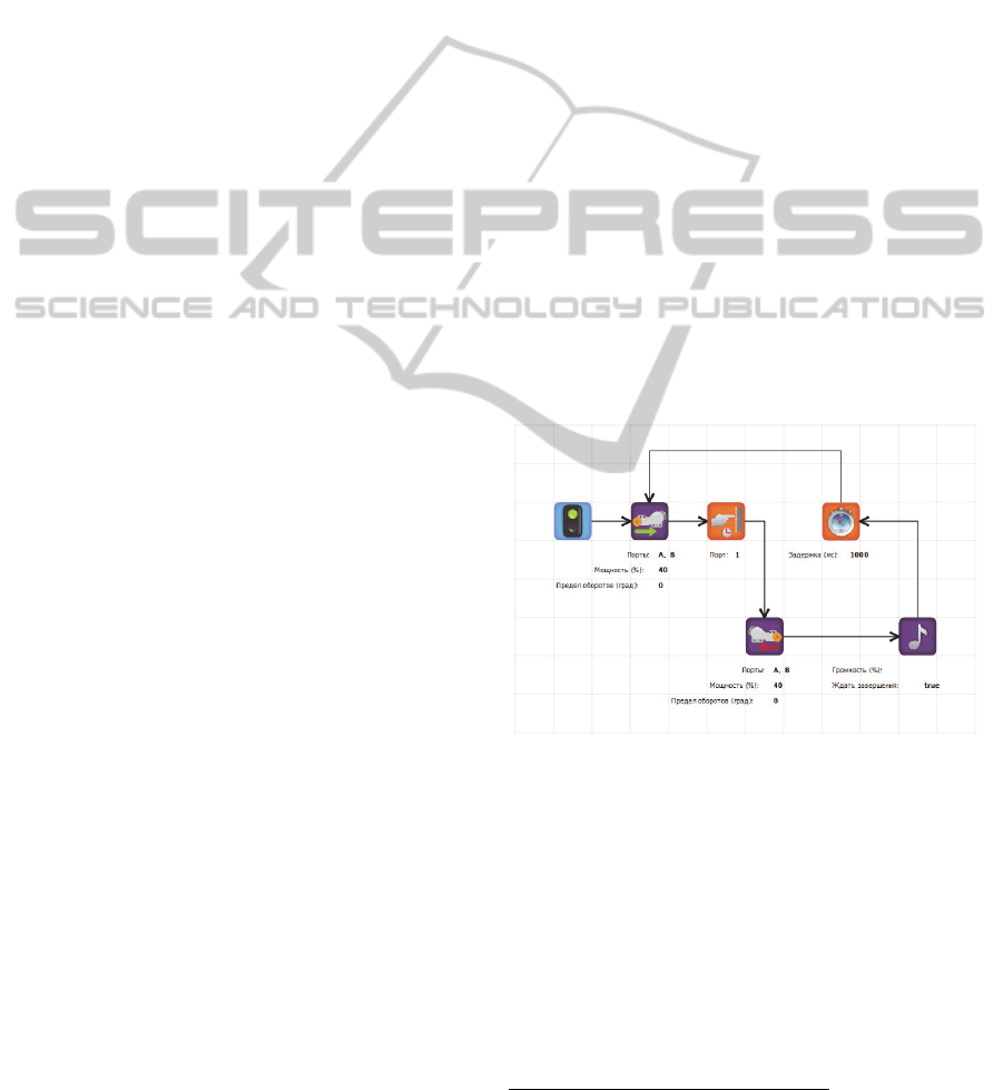
direct commands from a computer. QReal’s visual
language for robots represents a program as a
sequence of blocks connected with control flow
links. Blocks represent basic commands, such as
“Turn on a given motor on a given port with a given
power” or “Wait for a given period of time”.
Diagrams in this language are interpreted and
commands are sent into robots over Bluetooth or
USB. Currently executed block is highlighted on a
diagram. The visual language is simple and intuitive,
so it can be used even by elementary school
students. An example of a program in this language
is shown on figure 2.
Figure 2: An example of a program in QReal:Robots.
Specification of the language and creation of an
editor for it took approximately two hours, most of
the time was spent searching for suitable icons on
the Internet, and can be successfully maintained by
students after quick introduction to QReal's
metaeditor. For comparison, coding this editor by
hand even with good framework would have taken
several man-months of effort. All robot-specific
parts of this solution (Bluetooth and USB support,
generation of C code, its compilation and uploading
3
LEGO Mindstorms NXT 2.0, URL: http://mindstorms.lego.com/
en-us/Default.aspx
QRealDSMplatform-AnEnvironmentforCreationofSpecificVisualIDEs
209

on a robot etc.) were hand coded and took much
longer.
Comparing to a case of Ubiq Mobile described
earlier this case can be considered much more
successful because of much more narrow scope of
the DSM solution. We did not need to create
arbitrary programs and try to visualize general-
purpose language, we restricted ourselves to simple
sequential programs consisting of simple commands
to a robot or program control statements, and all of
these blocks are clearly defined. Here we used
embedded textual language too, but only to specify
mathematical expressions, so it has no specific
syntax which user has to know before he or she can
use it. Of course, there are problems like in Ubiq
Mobile case – since expressions are specified in
textual language, we cannot properly visualize data
dependencies between blocks, so if someone uses a
variable before initializing it, it will not be clear
from a diagram. But such problems are considered
minor because diagrams tend to be small and
manageable. Created visual language has proven
itself to be very adequate for educational purposes.
5 CONCLUSIONS
Metamodel-based language specification and
automatic generation of visual editors based on
metamodels has proven to be an efficient technique
of developing languages and tool support for them.
As creation of new visual language can be done very
quickly it is possible to experiment with different
languages and try to create DSLs for domains where
the use of language-oriented methods was not
feasible before. QReal technology has already drawn
some interest not only in schools where there is a
need for a good robot programming tool, but also in
the industry. One of the recent applications ideas is
to create a visual language for specifying image
processing algorithms for computer vision. Earlier
QReal was successfully used in a computer vision
field to specify and generate various state machines.
Further research is needed to make possible not
only generation of visual editors but full tool support
for new languages, including generators, run-time
emulators etc. Also it is crucial to fully support
language development as first-class development
process, with language versioning and automatic
model migration, language metamodel component
libraries, browsers, various interconnections
between editors and generators, etc. As shown by
the robots DSL example, a domain-specific
modeling methodology opens possibilities which
otherwise are prohibitively costly.
REFERENCES
Lionel Briand, Davide Falessi, Shiva Nejati, Mehrdad
Sabetzadeh, Tao Yue. Research-Based Innovation: A
Tale of Three Projects in Model-Driven Engineering.
Model Driven Engineering Languages and Systems,
Lecture Notes in Computer Science, Volume 7590,
2012, pp 793-809
Tony Clark, Pierre-Alain Muller. Exploiting model driven
technology: a tale of two startups. Software & Systems
Modeling, October 2012, Volume 11, Issue 4, pp 481-
493
Parastoo Mohagheghi, Wasif Gilani, Alin Stefanescu,
Miguel A. Fernandez. An empirical study of the state
of the practice and acceptance of model-driven
engineering in four industrial cases. Empirical
Software Engineering, February 2013, Volume 18,
Issue 1, pp 89-116
Kelly, S., Tolvanen, J. Domain-Specific Modeling:
Enabling Full Code Generation // Wiley-IEEE
Computer Society Press. 2008. 448 pp.
Kieburtz, R., et al. A software engineering experiment in
software component generation, Proceedings of 18th
International Conference on Software Engineering,
Berlin, IEEE Computer Society Press, March, 1996.
Steven Kelly, Kalle Lyytinen, Matti Rossi, MetaEdit+: A
Fully Configurable Multi-User and Multi-Tool CASE
and CAME Environment // Proceedings of the 8th
International Conference on Advances Information
System Engineering, pp. 1-21, 1996.
Daniel Amyot, Hanna Farah, Jean-François Roy.
Evaluation of Development Tools for Domain-
Specific Modeling Languages. System Analysis and
Modeling: Language Profiles. Lecture Notes in
Computer Science, Volume 4320, 2006, pp 183-197
Jan P. Nytun, Andreas Prinz, Merete S. Tveit. Automatic
Generation of Modelling Tools. Model Driven
Architecture – Foundations and Applications. Lecture
Notes in Computer Science, Volume 4066, 2006, pp
268-283
Терехов А.Н., Романовский К.Ю., Кознов Д.В., Долгов
П.С., Иванов А.Н., REAL: методология и CASE-
средство для разработки систем реального времени
и информационных cистем, Программирование,
1999, № 5. C. 44-52. (in Russian).
Karagiannis, D.; Kühn, H.: Metamodelling Platforms.
LNCS 2455, Springer-Verlag, 2002, p. 182.
G. Rozenberg (ed.). Handbook of Graph Grammars and
Computing by Graph Transformation. Volume 1:
Foundations. World Scientific, 1997.
Hausmann J. Dynamic Meta Modeling: A Semantics
Description Technique for Visual Modeling
Languages. PhD Thesis, 2005, Paderborn, Faculty of
Computer Science, Electrical Engineering, and
Mathematics of the University of Paderborn. 326 p.
ENASE2013-8thInternationalConferenceonEvaluationofNovelSoftwareApproachestoSoftwareEngineering
210

Simon Lacoste-Julien, Hans Vangheluwe, Juan de Lara,
and Pieter J. Mosterman; Meta-Modelling Hybrid
Formalisms // Proceedings of IEEE International
Symposium on ComputerAided Control System
Design, printed by IEEE Computer Society Press,
2004. pp 65-70.
Timofey Bryksin, Yuri Litvinov, Valentin Onossovski,
Andrey N. Terekhov. Ubiq Mobile + QReal a
Technology for Development of Distributed Mobile
Services // 10th Conference of Open Innovations
Association FRUCT and the 2nd Finnish-Russian
Mobile Linux Summit: Proceedings, printed by State
University of Aerospace Instrumentation (SUAI).
2011. 232 p. pp 27-35.
А. Н. Терехов, Т. А. Брыксин, Ю. В. Литвинов и др.,
Архитектура среды визуального моделирования
QReal. // Системное программирование. Вып. 4.
СПб.: Изд-во СПбГУ. 2009, С. 171-196 (in Russian).
Брыксин Т. А., Литвинов Ю. В., Среда визуального
программирования роботов QReal:Robots //
Материалы международной конференции
"Информационные технологии в образовании
и
науке". Самара. 2011. С. 332-334 (in Russian).
Valentin Onossovski, Andrey N.Terekhov (2009): Ubiq
Mobile – a new universal platform for mobile online
services // Proceedings of 6th seminar of FRUCT
Program.
QRealDSMplatform-AnEnvironmentforCreationofSpecificVisualIDEs
211
