
A Linearvibrotactile Actuator for Mobile Devices
Sang-Youn Kim
1
, Bonggoo Kim
2
and Tae-Heon Yang
3
1
Interaction Lab., Advanced Technology Research Center, Korea University of Technology and Education (KoreaTech),
(330-708) 1600 Chungjeolno, Byeongchunmyun, Chungnam, Cheonan, Korea
2
R&D Center, Yeonhab Precision Co. Ltd, (330-844)219-27 Haksusosa-gil, Mokcheon-eup, Chungnam, Cheonan, Korea
3
Korea Research Institute of Standards and Science, Daejeon, Korea
Keywords: Vibrotactile Actuator, Haptics, Mobile Device, Vibration.
Abstract: Although, the current vibrotactile actuators are widely used for haptic interaction with mobile devices, they
have still problems to be solved before accepting in many mobile devices. The most critical problem is that
the conventional vibrotactile actuators creates vibrotactile signal with limited frequency bandwidth. The
vibrotactile actuator with large frequency bandwidth allows a user to delicately and immersively manipulate
mobile devices. This paper presents a new vibrotactile actuator which creates vibrotactile signals with a
large frequency bandwidth. In our actuators, vibrotactile signal is generated by interaction between
solenoids and a permanent magnet. Experiments are conducted to investigate whether the proposed actuator
generates enough output force to stimulate human skin across a large frequency bandwidth. The result of the
experiments demonstrates that the proposed actuator is suitable for the haptic interaction with mobile
devices.
1 INTRODUCTION
Recently, the mobile industry is experiencing rapid
growth. As computer graphics, multi-media, and 3D
sound technologies are incorporated into the mobile
device, the devices are expected to be smarter and
smarter. According to Microsoft, 4 billion mobile
phones are in use all around the world (Microsoft
Tag, 2012). A market share of smart phones, which
is 25% in 2012, will balloon to 54% (IHS iSuppli,
2012). Due to the smart phones, the function of a
mobile phone has shifted from a traditional
telephone to an entertainment device with which a
user enjoys internet, movies, games, and etc.
Since visual information is most important factor
in interacting with mobile devices, mechanical
keypads and buttons in mobile devices are being
replaced by touch screens to maximize the display
area. A touch screen without a mechanical keypad
has led to a native user interface (UI) which reduces
the learning curve of a user to adapt usage of an
application. Enlarged screens and native UI allow a
user to intuitive and immersive interaction with
mobile devices. However, it is not easy to increase
the level of the immersion to the level where users
are truly “immersive”. To increase the level of the
immersion, many researchers and developers
focused on creating haptic feedback. The reason is
that interaction based touch is first way, and it
allows a user to non-verbally and cognitively
interact with devices. Therefore, haptic information
coupled with visual and/or audio information
enables a user to inattentively interact with devices.
Haptic feeling consists of tactile sensation
(sensory information acquired by pressure receptors
in the skin) and kinesthetic sensation (sensory data
obtained by receptors in joints, muscles, and
ligaments). Many haptic actuators that directly
provide kinesthetic force or pressure are too bulky to
be inserted them into mobile phones. Therefore, for
creating haptic feeling in mobile devices, many
researchers focused on tactile actuators because the
tactile actuators can easily be constructed in small
size. Among others, vibrotactile actuators have been
most widely studied to reproduce haptic sensations
on mobile screens by generating short vibration
feedbacks, and they have been successfully
commercialized in many mobile devices.
There are four major mechanoreceptors
(Meissner corpuscle, Merkel’s disk, Ruffini ending,
and Pacinian corpuscle) in the human glabrous skin
and their operating frequency are different from each
other except Ruffini ending (Johansson and Vallbo,
125
Kim S., Kim B. and Yang T..
A Linearvibrotactile Actuator for Mobile Devices.
DOI: 10.5220/0004525301250128
In Proceedings of the 10th International Conference on Signal Processing and Multimedia Applications and 10th International Conference on Wireless
Information Networks and Systems (SIGMAP-2013), pages 125-128
ISBN: 978-989-8565-74-7
Copyright
c
2013 SCITEPRESS (Science and Technology Publications, Lda.)
1979); (Johnson et al., 2000.). An eccentric motor,
which is the first commercialized vibrotactile
actuator, can create operating frequency in the range
of 80 to 250Hz. However it is not easy to generate a
variety of vibrotactile senation because the eccentric
motor creates concentrated force which is in
proportional to the square of the number of the
motor’s revolution. Another problem is that the
eccentric motor’s response time is too late to be used
for conveying vibrotactile sensation to a user in real
time. Therefore, a linear resonance actuator (LRA)
(Kweon et al., 2008) is developed to improve the
response time of the conventional vibrotactile
actuators. The LRA creates vibrotactile sensation
using resonant effect and its response time is fast
enough to be used for vibrotactile actuator. However
the strategy of vibration near the resonant frequency
limits frequency bandwidth of haptic actuators.
Piezo ceramic actuators have been developed for
producing vibrations with a wide frequency range
from a small device (Poupyrev et al., 2002);
(Wagner et al., 2005); (Cruz and Grant, 2011);
(Lylykangas et al., 2011). Even though a piezo
actuator can have possibility to selectively stimulate
mechanoreceptors, its vibrational force is not strong
enough to stimulate mechanoreceptors except at
their resonant frequencies.
Therefore, in this paper, we propose a linear type
vibrotactile actuator which not only creates
generates vibrations over a large frequency
bandwidth but also generate strong haptic effect
sufficient to stimulate human skin.
2 CONCEPTUAL DESIGN AND
IMPLEMENTATION
In this section, we describe a proposed vibrotactile
linear actuator consisting of a steel housing, a steel
flux path, steel ball bearings, two solenoid coils
fixed in a steel housing, two permanent magnets
passing in and out of the solenoid coils, and a link
bar that connects the two permanent magnets. The
steel flux path concentrates the magnetic field
strength in the gap between the steel flux path and
the steel housing. The steel ball bearings decrease
friction between the steel housing and the steel flux
path. Silicon was attached to both sides of the
solenoid coils to minimize the noise from collisions.
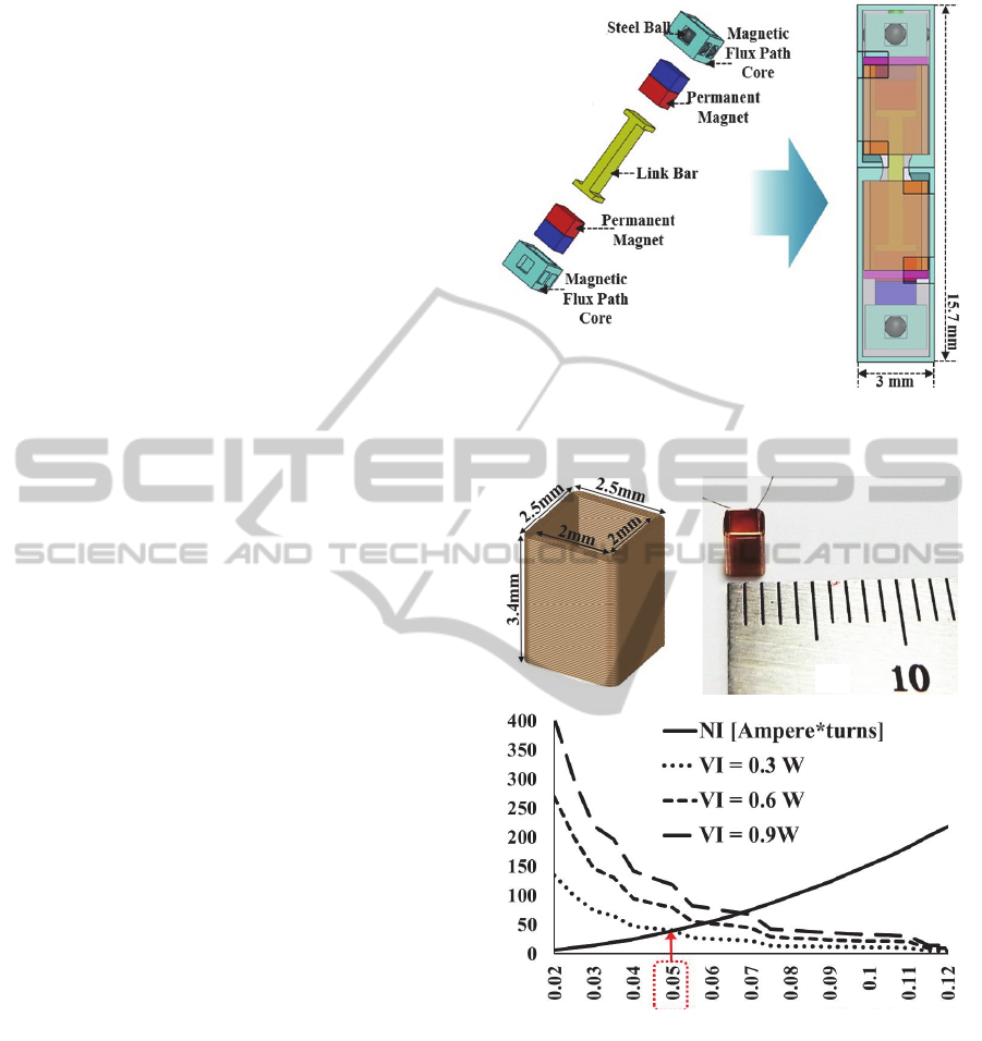
Fig. 1 shows the component of the proposed actuator
and its conceptual design.
Figure 1: Components of the proposed actuator and its
conceptual design.
(c)
(a) (b)
(
c
)
Figure 2: Parametric design of solenoid coil and its picture
In order to maximize the force of an actuator
with limited size, we conducted a parametric design
for a solenoid. Fig. 2(a) shows the parametric design
of the solenoid coil. The size of the solenoid coil
was determined by considering the size of the
housing and the permanent magnets. The inner
width and length of the solenoid coil was determined
to be 2 mm × 2 mm, and the outer width and length
was chosen as 2.5 mm × 2.5 mm. The height of the
coil was chosen as 3.4 mm. For this given size of the
SIGMAP2013-InternationalConferenceonSignalProcessingandMultimediaApplications
126
solenoid coil, the magneto-motive force (A • turns)
generated from the coil was simulated by changing
the wire diameter of the coil as shown in Fig.2 (b).
The wire diameter of the solenoid coil and the
number of turns needed to produce the desired
magneto-motive force (A • turns) were determined
to be 0.05 mm and 40 A•turns respectively (Fig. 2).
The chosen magneto-motive force (40 A • turns) was
applied in the FEM simulation to obtain the output
force of the actuator. Fig. 2(c) shows the fabricated
solenoid coil.
(i)
(ii)
(iii)
(iv)
(v)
(vi)
(i) : Upper Steel Flux Path, (ii) : Upper Permanent Magnet,
(iii) : Upper Solenoid Coil, (iv) : Lower Solenoid Coil,
(v) : Lower Permanent Magnet, (vi) : Lower Steel Flux Path
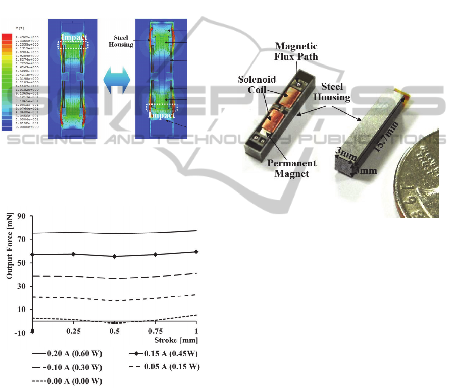
Figure 3: Working principle with FEM simulation of a
new impact actuator.
Figure 4: Result for FEM simulation.
Fig. 3 shows the working principle of the
proposed actuator and the simulation result when the
magneto-motive force of 40 A•turns was provided to
the two solenoid coils. The magnetic field from the
upper permanent magnet goes by the upper steel flux
path and then passes through the steel housing. After
that, the magnetic field returns to its original
position. Both permanent magnets can be moved up
and down according to the direction of the applied
current. In order to create a strong impact at the
downside of the proposed actuator, the upper and
lower permanent magnets are both pulled down by
the upper and lower solenoid coils, respectively. For
generating a strong impact at the upside, the two
permanent magnets are pushed up by the respective
solenoid coils. In this manner, repulsive and
attractive forces are created by the Lorentz force
between the permanent magnets and the solenoid
coils. The two permanent magnets and the solenoid
coils produce a linear Lorentz force according to the
direction of the stroke.
Figure 5: The developed actuator.
The vibrational impact force was 76mN when a
current input of 0.2 A is supplied to the actuator.
When there is no current input to the proposed
actuator, output force becomes 1.5mN which is
lower than absolute threshold (Lederman, 1997;
Katz, 1989).
Fig. 5 shows the constructed actuator prototype.
The solenoid diameter is 2.5 mm and its height is 3.4
mm. The two permanent magnets are installed at the
ends of the link bar with their north poles facing
each other. The two steel flux paths are mounted at
the outside ends of the corresponding permanent
magnets. The moving part travels linearly inside the
two solenoid coils due to the Lorentz force. The two
solenoid coils and the moving part are located inside
the steel housing that has two covers (the upper and
lower covers). When current is applied to the
solenoids, the permanent magnet moves from the
initial position to the other end and collides with a
silicon bumper attached to the end of the solenoid
coils. This collision generates strong and sharp
impact vibration. The size of the developed impact
vibration actuator is 3 mm × 3 mm × 15.7 mm.
ALinearvibrotactileActuatorforMobileDevices
127

Since the volume of the proposed actuator
(141.3mm
3
) is smaller than that of commercial linear
resonance actuators (360 mm
3
), the proposed
actuator can be easily embedded in mobile devices.
3 CONCLUSIONS
In this paper, we presented a tiny vibrotactile
actuator, which is easily embedded into mobile
devices, consisting of the moving part, two solenoids,
a steel housing, and two covers. Since the proposed
actuator provides enough working frequency and
output force to stimulate human skin, it can
selectively stimulate human’s mechanoreceptors.
According to the current input, the moving part runs
from the initial position to the other end and collides
with a silicon bumper attached to the end of the
solenoid coils in order to generate vibration. Our
work underscores the importance of the proposed
haptic actuator to enable users to experience
immersion while interacting with mobile devices.
ACKNOWLEDGEMENTS
This research was supported by the Basic Science
Research Program through the National Research
Foundation of Korea (NRF) funded by the Ministry
of Education, Science and Technology (grant
number : 2011- 0009757).This research was also
supported by the Dual Use Program Cooperation
Center (Development of tactile display device for
Virtual reality-based flight simulator, 12-DU-EE-03)
REFERENCES
Amemiya, T., Ando, H., and Maeda, T., 2008. Lead-me
interface for a pulling sensation from hand-held
devices. ACM Trans.Appl.Percept., 5(3), 1-17.
Blackberry storm2 touchscreen phone. http://us.
blackberry.com/smartphones/ blackberry-storm-2.html
Cruz, M., & Grant, D. (2011). High Definition Haptics for
Consumer Electronics. IEEE International. Conference
on Consumer Electronics (ICCE), Las Vegas, USA,
57-58
IHS iSuppli, 2012, http://gigaom.com/mobile/ by-2013-it-
will-be-a-smartphone-majority-world/
Johansson, R. S., & Vallbo, A. B., 1979. Tactile
Sensibility in the Human Hand: Relative and Absolute
Densities of Four Types of Mechanoreceptive Units in
Glabrous Skin. Journal of Physiology, 286, 283-300
Johnson, K. O., Yoshioka, T., & Bermudez F.V., 2000.
Tactile functions of mechanoreceptive afferents
innervating the hand. Journal of Clinical
Neurophysiology, 17, 538-558
Katz, D.,1989. The World of Touch. Erlbaum, Hillsdale
Kweon, S. D., Park, I. O., Son, Y. H., Choi, J., & Oh, H.
Y., 2008. Linear vibration motor using resonant
frequency. US PATENT, 7, 358633 B2
Lederman, S. J., 1997. Skin and Touch. Encycloedia of
Human Biology, Second Edition, 8, 49-61
Lylykangas, J., Surakka, V., Salminen, K., Raisamo, J.,
Laitinen, P., Rönning, K., & Raisamo, R., 2011.
Designing Tactile Feedback for Piezo Buttons. ACM
CHI Conference on Human Factors in Computing
Systems, Vancouver, BC, Canada, 3281-3284
Microsoft Tag, 2012. http://tag.microsoft.com/community/
blog/t/the_growth_of_mobile_marketing_and_tagging.
aspx
Poupyrev, I., Maruyama, S., & Rekimoto, J., 2002.
Ambient Touch: Designing Tactile Interfaces for
Handheld Devices, ACM Symposium on User
Interface Software and Technology, Paris, France,
October
Wagner, M., Roosen, A., Oostra, H., Hoppener, R., &
Moya, M. D., 2005. Novel Low Voltage
Piezoactuators for High Displacements. Journal of
Electroceramics, 14 (3), 231-238
SIGMAP2013-InternationalConferenceonSignalProcessingandMultimediaApplications
128
