
Reduction of Reactive Power for Power Saving Utilization
at Home Power Lines
Ondrej Krejcar and Robert Frischer
Department of Information Technologies, Faculty of Informatics and Management, University of Hradec Kralove,
Rokitanskeho 62, Hradec Kralove, Czech Republic
Keywords: Reactive Power Reduction, Real Time Systems, Measurement, Industrial Electronics.
Abstract: In recognition of the ever increasing energy prices, reactive power compensation is getting more and more
into the forefront. Climate protection and energy is one of the most discussed issues of current policy.
Production of electrical energy from primary sources to its consumption occurs however in the process of
losses. Although these total losses are obviously only a small portion of the current-dependent losses in
electricity transmission, the final absolute value of those losses go to billions of kilowatt. Part of the current-
dependent losses in networks raises inductive reactive power from the operation of common appliances.
Many home electric appliances like refrigerators, deep-freezes, washing machines, washers, pumps, etc.
produce vaste energy called reactive power, which can be reduced. This technique can lower electricity
consumption (from 10 to 30% - different by countries). Current possibilities of devices for reduction of
reactive power for home usage are only very limited with high price. Paper deal with a development of
miniaturized solution based on 32b MCU (Micro Controller Unit) with wireless communication unit and
independent powering circuit. We mentioned need of a very fine measurement of an input voltage and
current as well as remote monitoring option.
1 INTRODUCTION
If there is a need to power device, with working
current about 30Amp, a common solution now
seems not very realistic. Price of these devices is
very high. Isolation transformer which intended to
deliver more than 30Amp is very heavy and huge in
dimensions. Autotransformer is good alternative, but
price also remains high. AC/AC switching power
converter is dramatically smaller, but its price is
more than 3 times greater. Also switching frequency
in order of tenth kHz is useless, when powering
standard AC devices, like street lights, electrical
engines and so on. We have to develop a possibility
to electronically lower input RMS voltage, while
maintain low price and dimensions. The basic
principle is to use semiconductor switching device
and proper driving circuit, which can achieve
demand results. In the further text we will call that
device the reductor. Main and only purpose of these
devices is in its ability to reduce output power,
which will lead to the energy savings.
Our task was to design the device, which can
simply lower input AC RMS voltage, while high
current can pass through it, without using isolation,
or autotransformer. Overal dimensions have to
remain small as well as the weight. Output voltage
should be smoothly adjustable through any standard
interface (UART, RJ-485, USB). Basically we had
two options. The first was to build an AC/DC/AC
converter, mostly known as frequency converter.
This option was refused, because of lower overall
efficiency and relatively high complexity. Also
switching semiconductors are relatively high on
price and are susceptible to over current and over
voltage conditions. The second option was to
develop the device, which is based on triac basis.
Driving using triac is very widespread. Mostly
are these devices used as speed regulation in drills.
Principle is the same, but overall design is
somewhere else. Drilling speed regulation is
designed to drive current machine. Connecting
another one can harm the target device, or overheat
and damage driver itself. On the other hand, currents
over 30Amp aren't too much widespread in drills,
because of the overall size (12kW drill is fairly
heavy).
In present day, most solutions are based on
477
Krejcar O. and Frischer R..
Reduction of Reactive Power for Power Saving Utilization at Home Power Lines.
DOI: 10.5220/0004582804770484
In Proceedings of the 10th International Conference on Informatics in Control, Automation and Robotics (ICINCO-2013), pages 477-484
ISBN: 978-989-8565-70-9
Copyright
c
2013 SCITEPRESS (Science and Technology Publications, Lda.)
autotransformer basis. Into the main power line is
putted the transformer, which lower input voltage to
the demand level.
Input voltage is lowered on demand level by
inserting the primary/secondary winding to the
power path. One advantage is that output voltage has
the same running as input voltage. There is
significantly shifted current over the voltage, but
essentially it isn't a problem. This shift is caused by
inductance of the transformer. It can be
compensated, but this is another issue.
Autotransformer is significantly smaller than
standard isolation transformer. Its secondary voltage
isn't separate from primary voltage. This feature
caused, that through the transformer core don't pass
all the power, and that's why it can be significantly
smaller. Overwhelming cases are solved by this
principle. There are also disadvantages. Secondary
voltage can't be adjusted smoothly. It has step
changes. Secondary winding has limited number of
turnings. Mostly output voltage changes are in order
of tens of volts and haven't continuous running, but
discrete. On every change, the output voltage
disengages for the while and it can cause visible
blinking of the light or perceivable kick on the motor
and so on.
In recognition of the ever increasing energy
prices, reactive power compensation is getting more
and more into the forefront of. Climate protection
and energy is one of the most discussed issues of
current policy. Electricity, which is a form of energy
with the highest credit rating, is in the centre of these
discussions. During the production phase of
electrical energy in power plants where it is burning
a coal, oil and gas, a carbon dioxide (CO2) is
primarily released in huge amounts, what negatively
affects the climate. Production of electrical energy
from primary sources to its consumption occurs
however in the processes of losses. Although these
total losses are obviously only a small portion of the
current-dependent losses in electricity transmission,
the final absolute value of those losses go to billions
of kilowatt. Part of the current-dependent losses in
networks arises inductive reactive power arising
from the operation of common appliances. These
losses can be avoided by offsetting.
2 PROBLEM DEFINITION
Electric components consume a power from the
electric network (power line), which is generally the
product of current and voltage. This performance is
taken further in the appliance and converted into
useful power, which is referred to as an active power
P.
When electrical appliances, working on the
induction principle, are connected to AC, (three-
phase current), they take from the power line an
extra power which is need to create a magnetic field
which is then fed back into the power line.
This "useless" - reactive power Q and shuttling
between the source (generator) and the appliance
inside and outside (Fig. 1) and in addition to the
active power P it burdens generators, transformers,
transmission lines of High and Very High Voltage
and electrical distribution system in Low Voltage
power lines.
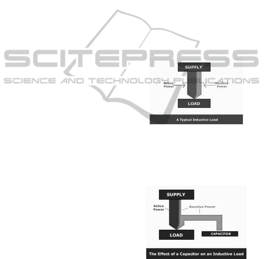
Appliance with no corrections of reactive power
as can be seen on (Fig. 1), the supply is required to
provide the total active and reactive power on
demand of the load.
Figure 1: Appliance with no corrections of reactive power.
At the other side, when appliance is installed with a
capacitor - electrically adjacent to a load, the supply
is required only to provide the active power on
demand. Only smaller proportion of the reactive
power is needed on demand from source power line
(Fig. 2).
Figure 2: Appliance is installed with a capacitor.
The vector sum of active and reactive power is
called apparent power and indicates a capital S.
Appliances in energetic grids are usually inductive
ICINCO2013-10thInternationalConferenceonInformaticsinControl,AutomationandRobotics
478
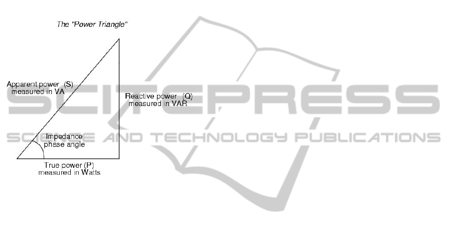
in nature. Reducing inductive reactive power can be
achieved by parallel connection of capacitors for
induction appliances. This makes returning reactive
power, which was used to create a magnetic field,
"stored" in the condenser and plies only between the
capacitor and the induction appliance. Power
capacitor has a capacitive and inductive directed
against the performance of the appliance. Power
factor when required, but incomplete compensation
of inductive reactive power changes from the cos φ
cos φ '(Fig. 3).
Figure 3: Reactive power introduction.
Problem of unstable running of electric power in
home or small office electric power line as well as
the low quality of electric power which can go up to
25 % in some cases led to the need of complex
solution to reduce or fully compensate mentioned
malfunctions.
Cases where is the extreme need of
compensation are mainly in computer solutions area,
where some specific applications need very precise
and stabile voltage running (in other case the used
technology can became broken or damaged).
All mentioned problems also grow up in home or
small offices, where some common electrical
appliances are widely used. As example it can be
specify as refrigerators, freezers, home pumps, hair
dryers, and other examples containing electrical
engines (motors).
Mentioned problems grown up only in home or
small office cases, because at a higher level power
lines (mid-size and large size companies) a
regulation from government need to be done every
time (Corcorana et al., 2012). Large companies need
to take care of quality of their power lines alone and
the solutions are well known widely even in the
markets.
Nowadays a power consumption still growing up
due to the usage of many electrical appliances even
in case the users bought energy save devices. (Yang,
2008), (Cohen, 2012).
Based on previous discussion a problem of home
power lines can be defined as a need of:
Overvoltage reduction;
Decreasing phase shift;
Increasing of appliances lifetime (up to 40%);
Increasing of quality of power for power line;
Decreasing of environmental sources consumption;
Decreasing of electric power consumption by 25
%;
Low cost solution – quick recovery of investment.
Following chapter will discuss existing solutions for
partial or complete (if exists) solving of defined
problems.
3 RELATED WORK
There are many existing solutions for reactive power
shifting or reducing like one from (Rathika and
Devaraj, 2010), where they developed a solution of
fuzzy logic-controlled shunt active power filter
which is capable to reduce the total harmonic
distortion. Their simulation results show some level
of effectiveness of proposed solution for harmonic
reduction, not for power line quality nor the power
save. This solution can be used to solve only
particular solution.
Another authors (Gao and Peng, 2010) presents
two methods to reduce the reactive power at
converter topology level and control level
respectively. Presented study has been performed to
decrease the total reactive power for real tokamak to
reduce the overvoltage and to avoid low-frequency
resonant caused by the fast and large reactive power
variation within 20ms. Solution of tokamak is quite
far of home power line usage, but there are some
interesting and usable techniques, which can be
partially used. This is however not complex solution
as requested.
Third research paper (Zhao et al., 2009) describe
a wind farm which is made with doubly fed
induction generators (DFIG) as the continuous
reactive power source to support system voltage
control due to the reactive power control capability
of DFIG. The particle swarm optimization (PSO) is
utilized to find wind farm optimal reactive power
output for distribution system losses reduction and
voltage profiles improvement. Finally, the three
feeder distribution system is used as a test case to
evaluate the algorithm. This solution is almost the
best of each ones we found in research databases,
ReductionofReactivePowerforPowerSavingUtilizationatHomePowerLines
479

but the cost of solution and complexity is too high
for home purposes.
The last one solution we found as a literature
with topics close to our research (Rao and Vaisakh
2006) deal with network sensitivity between load
voltages and source voltages, what is used as the
basis to evaluate optimal real power generation
allocation for loss and marginal cost reduction.
Authors also present a method for optimum
allocation of reactive power in day-to-day operation
of power system for loss reduction. The described
technique try to utilize fully the reactive power
sources in the system to improve the voltage profile
and to minimize the real power losses besides
meeting the optimal real power generation levels.
Although this paper describe very interesting
solution, there are a lot of missed technical details
without them it is not possible to run the system as
correctly as it is requested.
Due to the absence of research output with full
and complete low cost solution, we will describe
several methods in details as well as with all
technical knowledge, what is needed to develop
requested solution.
4 CURRENT STATE OF THE ART
Triac are in principle two antiparallel connection of
thyristors. Unlike the thyristor, it can conduct
current in both directions.
Triac drivers are relatively easy. There is a
threshold voltage resistor divider, snubber network
and triac. Triac has to be activated by single pulse
(For one half-period) to the gate electrode. Then the
passing current through the triac hold it in the
conduction state. One main disadvantage of the triac
against standard bipolar or unipolar switching
components is that it can't be switched off. Triac
close itself when passing current disappears. Then
remain in closed state until next trigger impulse is
generated. In the principle, we are cutting off part of
the sine wave. So the output running voltage isn't
clearly continuous but partly discrete. Maximum and
minimum voltage levels are preserved. One thing
which will change is value of RMS voltage.
Another annoying thing is ΔI/Δt transition. Value
about 100A/μs is very high a causing unwanted
disturbances on higher frequencies. This is maybe
most important thing, has to be solved, because any
disturbance may results in failure of the devices in
power line path.
4.1 Analog Triac Driving
Within the frame of solution were made two variants
of reductors. One was based on analog principle
while the other on the digital basis. The first one has
one major disadvantage. It was not able to control
output voltage continuously. There were resistor
networks with DIP switch, which control output
voltage level. This solution is perfect to one concrete
device. It is relatively simple and cheap, but it can't
accommodate to output or input changes. It has a
soft start function, which ensures a proper start of
the connected device. Another useful feature is
circuit, which is responsible to proper triggering of
the triac. If the triac is not able to sustain in open
state, this device is trying to trigger it again, until the
conduction mode is achieved. But this reductor was
only a temporary solution.
4.2 MCU based Triac Driver
Analog based triac drivers can't react quickly enough
to changes, which are common in real world.
Changes in load character, load amount, input
voltage level or reactive power present are real
issues. Especially reactive power is relatively
dangerous, because it can cause, that triac will
remain in conduction state, because of phase shift of
passing current. If we are using MCU (micro
controller unit), we can span every possible
occasion, we can imagine and make an algorithm to
precede it. In our case, MCU is measuring, among
others, input and output voltage. Main task is to
stabilize output voltage on demand level. So if we
have output voltage value, we can adjust trigger
pulse to be precisely in specific time which leads to
right RMS value. Having output voltage stabilized,
has one main advantage. If we are driving street
lights, voltage drop under safe level will lead to
further lamps will shut down. It is obvious, that right
timing is critical. MCU is monitoring input voltage
and current and their crossing through zero level.
This is an important moment, because its value is
proportional to passing reactive current. Also
triggering impulse is derived from this precise time.
Circuit which is responsible for recognition this time
is very simple. It is common comparator, which is
continuously comparing passing current with the
ground signal. If the current is negative, comparators
output is logical 0. As soon as the current rise above
the zero (ground) level, comparator turn over and its
output is logical 1. Same comparator is on the
voltage side and the time between both transitions is
ICINCO2013-10thInternationalConferenceonInformaticsinControl,AutomationandRobotics
480
proportional to phase shift between voltage and
current (reactive current). Matching resistor network
to measure high AC voltage and current is shown in
(Fig. 4).
Figure 4: Matching resistor network necessary when
measuring high AC voltage or current.
There are 3 resistors on input side. Two of them has
the same resistance value. They are two, because of
high voltage stress applied on them. Standard SMD
resistor has voltage rating about 200V. If the voltage
is higher, disruptive breakdown will occur and high
voltage appears on low voltage circuits parts.
Resistor divider then lower input voltage 241 times,
so the output voltage applied to MCU A/D inputs is
about ±1V. Negative part has to be override, because
of MCU inputs. Negative voltage can harm that
device, even if is as small as 1V (Fig. 4).
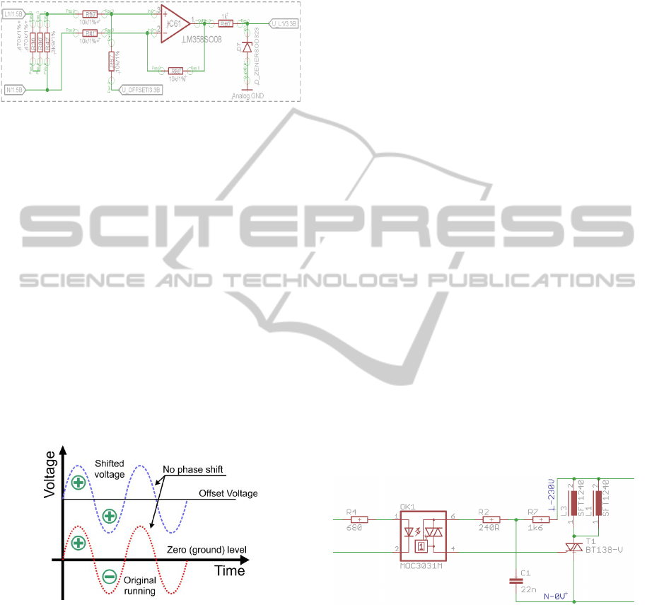
Operational amplifier is connected as differential
amplifier. Offset voltage is applied on non inverting
input, so the output signal is shifted up just about the
offset voltage (U_OFFSET). As a result, we have
the same voltage running as is present on the power
line, but proportionally lower and shifted up.
Figure 5: Shifting up input voltage to avoid negative
voltage to be present on MCU inputs.
This is very important thing and its principle is
presented on (Fig. 5).
Current measuring is in principle the same. The
most efficient way how to measure passing current
is to use current transformer. It is a widely used,
cheap component with a very simple principle.
Passing of AC current forms alternating magnetic
field, which induce a voltage on the secondary
winding. This is a contactless measuring form,
because the wire acts as primary winding and
magnetic lines are closing through the sensors
winding.
On the probes terminal a same voltage pattern as
passing current is presented (only proportionally
smaller). Of course, there is a small shift between
real current and probes recorded current, but if a
proper components are used, this error is smaller
than 1%. This wave is also differentially scanned
and shifted up to sustain ability to measure both half
waves.
Now can be these running converted to digital
area. Each period is sampled with 20.000 Hz
sampling rate. It is equal to 400 sampled points per
period. These data are stored in external SRAM
memory, because MCU itself has not enough
memory capacity. We tried to increase number of
sampled points, but results remain almost the same.
So it appears to be sufficient number.
5 REDUCTOR DESIGN
It's not easy to drive triac. There is a high voltage on
its gate electrode. MCU and support circuits are
supplied from low voltage power source (5V). The
question is, how to switch ON triac by low voltage
source. Essentially we have got only one possibility.
Using an opto-coupler is an elegant way how to
make this possible. Opto-coupler has the LED on its
one side, and opto triac on the other. Activated LED
caused switch opto triac ON. This principle is on
(Fig. 7).
Figure 7:
Using low voltage Opto-Triac to drive high
voltage, power Triac
.
This type of driving has one more advantage. We
can control unwanted ΔI/Δt transition by setting R7
and C1 values. If the opto triac starts to conduct,
current from input (L-230V) passing through the R7
and R2 resistor to the T1 gate. It will cause to switch
main triac ON. Triggering impulse has to deliver at
least 50mA. Once the triac is opened, passing
current will keep it open.
Snubber network created by R7 and C1 will limit
ReductionofReactivePowerforPowerSavingUtilizationatHomePowerLines
481
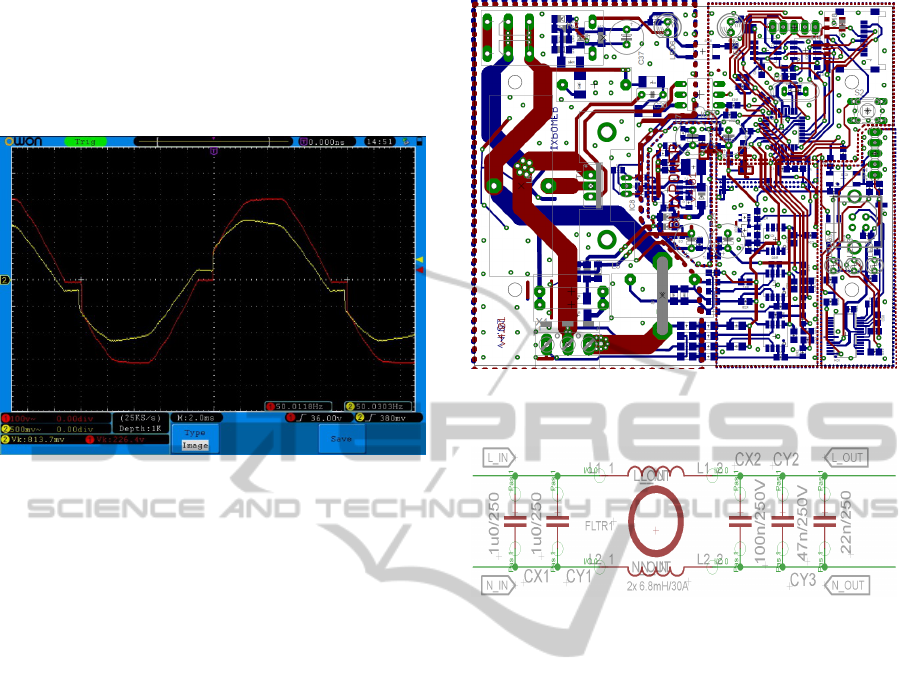
initial current slope to tolerable level. In addition it
can limit switching disturbance by shorting high
frequency transients. In case, that we wouldn’t use
snubber network, the output would be like in the
(Fig. 8).
Figure 8: High ΔI/Δt transient causing high RF
disturbance.
ΔI/Δt transition can be partly controlled by snubber
network, but it servers only as supplementary item.
Main ΔI/Δt limiter is caused by series inductor L1
and L3. They are connected at parallel, to increase
current rating. If the hi current slope appear,
inductance will counteract and slowdown the slope
to convenience level. There is a one important thing.
Inductor core material has to be chose carefully,
because for example ferrite core can't handle low
frequency current and then acts like ordinary serial
resistance. That led into that no ΔI/Δt reduction is
present. There should be use standard iron core
inductors with proper inductance if we are working
with standard 50/60Hz current.
As we mentioned above high current slope levels
are causing high disturbance into the main power
line. To precede this state, special care must be
devote to PCB design. Power traces must be as short
as possible and ground signal has to be spilled out
on the PCB. PCB design is shown in (Fig. 9). This
device must work in cooperation with passive filter
to avoid passing disturbance back into the power
line path. Without this filter it can't be connected to
the customer line, because of EMC (Electro
Magnetic Compatibility) law violating.
EMC filter can be calculated, but final inductor
and capacitor values must be trimmed on the basis of
practical tests. Electrical scheme of this filter is
common (Fig. 10).
Figure 9: Reductors PCB design. Power traces has to be as
short as possible.
Figure 10: Passive filter to satisfy EMC.
This special device is called suppression choke. This
filter must reduce high frequency disturbance and
that's why must be inserted between interconnecting
wires and useful and disturbing current must pass
through it. For low frequencies is reactance of
inductor very low and essentially has no affect to
passing current. On the contrary, disturbing, high
frequency signal is suppressed by high reactance of
the inductor. Suppression function of the inductor is
especially expressive in circuits with low
impedance, where impedance of the source and load
are much lower, than reactance of the inductor.
Suppression chokes are mostly wind on ferrite or
iron chokes, mostly toroidal shapes. On (Fig. 10) is
presented choke with unusual winding. There are
two windings on the same choke. Wires are
connected as we can see on the figure. So the
magnetic flow generated by working current is
compensated. Core is than saturated only by
unsymmetrical currents. That led to suppress
unsymmetrical disturbances which are generated
from triac switching.
Except inductors, there are present also
capacitors. For low frequencies the capacitor acts as
high reactance, so the impact to the power line is
insignificant. On the contrary high frequency noise
ICINCO2013-10thInternationalConferenceonInformaticsinControl,AutomationandRobotics
482
is suppressed, because of low reactance of the
capacitor. Good filter is essential. Without it,
disturbance can harm any connected device on the
power line and in addition EMC doesn't meet.
6 ADDITIONAL FEATURES
OF REDUCTOR
The reductor device is primary intended to lower
RMS voltage in order to lower output power (it
means energy savings). If we pass away problems
with triac switching and EMC issues, we can focus
to the other problems like low switching current
issue, over current state, smooth transients,
communications protocols, real time clock (RTC),
data recording and so on (Dodiu et al., 2010).
Low switching current can be problematic. If we
have no sufficient current, triac after successful
triggering to conduction state can't feed itself and
turn to off state. This state can cause unwanted
disturbance, which infest power line. To
successfully avoid this state, the intelligent bypass is
present. If the device detects current under the
threshold level, a relay is switched on (or high
current clamper). This relay will bypass the triac and
everything goes well. Similar state can occur when
over current is detected. Over current can harm triac
and destroy the reductor. So if the reductor detect
over current state, relay again involve.
If the power saving should be sensible, RMS
voltage level has to be lowered about 20V at least.
This could cause unwanted power step, which is
visible as a little blink (street light or something
like). This blink is common phenomenon when
using standard reductors from most vendors. If we
have MCU as a control unit, we can program its
behavior to reduce RMS voltage level gradually, in
small steps, with variable time between them. MCU
has 16bit timer which give us theoretically about
65.000 voltage steps, in voltage expression one steps
equal to 3.5mV. In comparison to autotransformer it
has to have 65 thousand taps. Practically it has no
meaning, so about 2 thousand steps were chosen. It
is enough to smooth transition from full power state
to reduction state without noticing. Reductor block
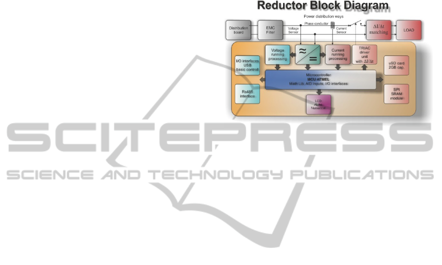
diagram is presented on (Fig. 11).
So as we can setup the device and precede all
unwanted states, we need to know all details about
power line, voltage and current levels, reactive
power amount, switching details, load character and
of course also time. If problem once originate,
without history data we can only guess, what
happened. For that reason RTC (Real Time Clock)
and data recording function is present. RTC has its
own backup battery, so it can function over the
period without AC line voltage. Measured data are
periodically saved on microSD card with the current
time stamp. Time spacing between records are set to
3s. It is enough to evaluate incurred problem.
Figure 11: Reductor block diagram (Krejcar and frischer,
2012).
7 CONCLUSIONS
Presented device is an alternative to robust and
heavy transformer based energy savers (reducer).
Unlike them, this device uses active semiconductor
switching topology to reduce RMS voltage. Smooth
transitions of output voltage make it ideal to drive
any kind of lights. Any change isn’t noticeable and
that’s the thing that customer want. Many other
features make a complex unit, which is suitable to
analyze problems in power line path. Also price is
much lower than in competitor’s ($300).
ACKNOWLEDGEMENTS
This research was funded by a grant (Smart
Solutions in Ubiquitous Computing Network
Environments) from the Grant Agency of
Excellence, University of Hradec Kralove, Faculty
of Informatics and Management, Czech Republic
and by a grant (SP/2013/03 - SmartHomePoint
Solutions for Ubiquitous Computing Environments)
from University of Hradec Kralove. This research
was performed in cooperation with the Cautum
Company (http://cautum.cz/).
REFERENCES
Alturki, Y. A., Lo, K. L., 2010. Real and reactive power
ReductionofReactivePowerforPowerSavingUtilizationatHomePowerLines
483

loss allocation in pool-based electricity markets,
International Journal of Electical Power & Energy
Systems.Elsevier: England, Vol. 32, Issue 4, pp. 262–
270.
Augustynek, M.; Penhaker, M. Non invasive measurement
and visualizations of blood pressure. Electron. Electr.
Eng. 2011, 116, 55–58.
Brida P., Machaj J., Duha J., 2010. A Novel Optimizing
Algorithm for DV based Positioning Methods in ad
hoc Networks, Electronics and Electrical Engineering.
Vol. 97, Issue 1, pp. 33–38.
Cohen, M., S., 2012. Increasing Power Consumption
Awareness in Critical Communications Sites with Fuel
Cells, IEEE 34th International Telecommunications
Energy Conference (INTELEC), Scottsdale, AZ, USA.
Corcorana, B., A., Jenkinsb, N., Jacobson, M., Z., 2012.
Effects of aggregating electric load in the United
States, Energy Policy, Vol. 46, pp. 399–416
Deacon, C. G., Clarke, H. C., 1993. Use of a Linear Offset
Hall-Effect Transducer in Student Laboratory
Experiments to Measure Magnetic-Fields, American
Journal of Physics. Vol. 61. Issue 10.pp. 947–948.
Dodiu E., Graur A., Gaitan V. G., 2010. Hard-Soft Real-
Time Performance Evaluation of Linux RTAI Based
Embedded Systems, Electronics and Electrical
Engineering. Vol 104, Issue 8, pp. 51–56.
Gao, G., Peng, F., 2010. Reactive Power Reduction at
Converter Level, Proceedings of the 5th IEEE
Conference on Industrial Electronics and
Applications, (ICIEA 2010), Vol 2, pp. 592-597.
Kami, Y., Xiao, F., Murano, K., Mode-Port-Network
Approach to Analyze Power-Line EMC Problems for
PLC, 20th International Zurich Symposium On
Electromagnetic Compatibility, PP. 73-76, 2009
Krejcar, O., Tucnik, P., Adamec, O., 2011. Evaluation of
aJile aJ-80 Real-Time embedded platform for RT-Java
parameters, Measurement, Volume 44, Issue 7, 2011,
pp. 1253-1260
Krejcar, O., Frischer, R., 2011. Real Time Voltage and
Current Phase Shift Analyzer for Power Saving
Applications”. Sensors. vol. 12, Iss. 8, pp. 11391-
11405, 2012. DOI 10.3390/s120811391.
Rao, G. V. S. K., Vaisakh, K., 2006. Optimal real and
reactive power allocation for real power loss and
marginal cost reduction, Proceedings of the Sixth
IASTED International Conference on European Power
and Energy Systems, Rhodes, Greece, JUN 26-28,
2006, pp. 51-56.
Rathika, P., Devaraj, D., 2010. Artificial Intelligent
Controller based Three-Phase Shunt Active Filter for
Harmonic Reduction and Reactive Power
Compensation, International Multiconference of
Engineers and Computer Scientists (IMECS 2010),
Lecture Notes in Engineering and Computer Science,
pp. 1170-1175
Tutsch, M.; Vojcinak, P.; Koziorek, J.; Skrepek, M. Using
Automated Evaluation of Efficiency for Photovoltaic
Power Plant. In Proceedings of the IEEE 16th
Conference on Emerging Technologies and Factory
Automation (ETFA), Toulouse, France, 5–9
September 2011; pp. 1–4.
Welchko, B. A., Analytical calculation of the RMS current
stress on the DC link capacitor for a VSI employing
reduced common mode voltage PWM, 2007 European
Conference On Power Electronics And Applications,
pp. 2232-2239, 2007
Wurtz, E., Mora, L., Inard, C., 2006. An equation-based
simulation environment to investigate fast building
simulation, BUILDING and ENVIRONMENT, vol.
41, Issue: 11, pp. 1571-1583.
Yang, S. X., 2008. Forecasting increasing rate of power
consumption based on immune genetic algorithm
combined with neural network, Journal of Central
South University of Technology, Vol. 15, pp. 327-330,
DOI: 10.1007/s11771-008-0481-1
Zhao, J. J., Li, X., Hao, J. T., Zhang, C. L., Lu, J. P., 2009.
Wind Farm Reactive Power Output Optimization for
Loss Reduction and Voltage Profile Improvements,
6th IEEE International Power Electronics and Motion
Control Conference, Wuhan, Peoples Republic of
China, MAY 17-20, 2009, Pages: 1453-1457.
ICINCO2013-10thInternationalConferenceonInformaticsinControl,AutomationandRobotics
484
