
Estimation of User’s Motion Intention of Hand based on Both
EMG and EEG Signals
Kazuo Kiguchi
1
and Yoshiaki Hayashi
2
1
Department of Mechanical Engineering, Kyushu University, Fukuoka Japan
2
Department of Advanced Technology Fusion, Saga University, Saga, Japan
Keywords: Motion Estimation, EEG Signals, EMG Signals.
Abstract: A surface EMG signal is one of the most widely used signals as input signals for wearable robots. However,
EMG signals are not always available to all users. On the other hand, an EEG signal has drawn attention as
input signals for those robots in recent years. However, the EEG signal does not have straightforward
relationships with the corresponding brain part. Therefore, it is more difficult to find the required signals for
the control of the robot in accordance with the user’s motion intention using the EEG signals compared with
that using the EMG signals. In this paper, both the EMG and EEG signals are used to estimate the user’s
motion intention. The EMG signals are used as main input signals because the EMG signals have higher
relative to the motion of a user. The EEG signals are used as sub signals in order to cover the estimation of
the user’s motion intention when all required EMG signals cannot be measured. The effectiveness of the
proposed method has been evaluated by performing experiments.
1 INTRODUCTION
In advanced countries, aging of the society with low
birthrates is a serious problem. It is very important
to assist the daily living of physical weak persons in
order to make them live the independent lives. To
assist daily life motions of the physically weak
persons such as elderly, injured, or disabled persons,
many kinds of power-assist robots and robotic
artificial limbs have been developed (Yang et al.,
2008); (Escudero et al., 2002). Those robots are
required to generate the proper motion according to
a user’s motion intention because the robots need to
prevent a user from uncomfortableness. To activate
the robots according to a user’s motion intention, the
biological signals are often used as input signals for
those robots.
In the biological signals, a surface
electromyogram (EMG) signal is one of the most
widely used signals as input signals for wearable
robots. An EMG signal is an electric signal which is
generated when a muscle is activated. Therefore, the
robots can estimate a user’s motion intention and
assist the estimated motion in real-time by
measuring multiple EMG signals. However, EMG
signals that are needed to estimate the motions of a
human upper-limb are not always available to every
user. For example, persons who lost their limb due
to an accident or a sickness are not able to prepare
EMG signals because they lost some necessary
muscles. Furthermore, paralyzed patients are also
not able to prepare EMG signals. In addition, the
correct locations of the electrodes are difficult to
find for some surface EMG signals. If all required
EMG signals for the control of the robots cannot be
measured, other input signals must be prepared
instead of EMG signals.
On the other hand, electroencephalogram (EEG)
signals are used as input signals for various robots in
recent years. An EEG signal is an electric signal that
can be measured along a scalp. Therefore, the EEG
signals can be measured even with amputees and
paralyzed patients who are not able to generate some
(or all) EMG signals. An EEG signal is one of the
strong candidates for the additional input signals for
wearable robots, and it will be able to allow more
users to use those wearable robots. The interface
between a robot and EEG signals is called as Brain
Computer Interface (BCI). Until EEG signals were
used for the control of the robots, the researches on
offline analysis of EEG signals were mainly carried
out. To detect event-related potential, evoked
potential, and so on, the averaging method,
frequency analysis and principal component analysis
447
Kiguchi K. and Hayashi Y..
Estimation of User’s Motion Intention of Hand based on Both EMG and EEG Signals.
DOI: 10.5220/0004590604470452
In Proceedings of the 10th International Conference on Informatics in Control, Automation and Robotics (ICINCO-2013), pages 447-452
ISBN: 978-989-8565-71-6
Copyright
c
2013 SCITEPRESS (Science and Technology Publications, Lda.)

are widely used in offline analysis. However, many
of those analyses require a certain length of time-
series data of EEG signals. Therefore, in general,
those analyses are not suitable for the real-time
control of the robots. On the other hand, some
classification methods that are used to control the
robotic systems in real-time were proposed (Novi et
al., 2007), (Fabiani et al., 2004). In addition, the
hand velocity is estimated from EEG signals in
recent years in the limited condition (Lv et al., 2010),
(Bradberry et al., 2010).
In the case of a surface EMG signal, although an
electrode is located on the skin, the measured EMG
signal has almost straightforward relationships with
the corresponding muscle as long as the electrode is
located correctly. On the other hand, in the brain,
various electric signals are generated at multiple
locations and are conveyed to the scalp. The sum of
those conveyed electrical signals on the scalp is
recorded as the EEG signal. Therefore, in the case of
an EEG signal, the measured EEG signal does not
have straightforward relationships with the
corresponding brain part. It is more difficult to find
the required signals for the control of the robot in
accordance with the user’s motion intention using
the EEG signals compared with that using the EMG
signals.
In this paper, both the EMG and EEG signals are
used as input signals for wearable robots, and
estimated the user’s motion intention of the upper-
limb based on the measured EMG and EEG signals.
In the proposed method, the EMG signals are used
as main input signals because the EMG signals have
higher relative to the motion of a user in comparison
with the EEG signals. The EEG signals are used as
sub signals in order to cover the estimation of the
user’s motion intention when all required EMG
signals cannot be measured. The effectiveness the
proposed method has been evaluated by performing
experiments.
2 MEASUREMENT OF EMG
AND EEG SIGNALS
In this study, to estimate a user’s upper-limb motion,
EMG and EEG signals are used. A human’s upper-
limb basically has 7 degrees of freedom (shoulder
vertical and horizontal fle./ext. motion, shoulder
int./ext. rotation motion, elbow fle./ext. motion,
forearm supination/pronation motion, wrist fle./ext.
motion and wrist radial/ulnar deviation motion).
In the case of EMG signals, 16 EMG signals are
used to estimate 7 DOFs’ motion of a user’s upper-
Table 1: Muscle for each EMG channel.
Ch. Name of muscle Related major motion
ch. 1 Deltoid-anterior
Shoulder vertical fle.
Shoulder horizontal fle.
Shoulder int. rotation
ch .2 Deltoid-posterior
Shoulder vertical ext.
Shoulder horizontal ext.
Shoulder ext. rotation
ch. 3 Pectoralis major-clavicular
Shoulder vertical fle.
Shoulder horizontal fle.
ch. 4 Teres major
Shoulder int. rotation
Shoulder vertical ext.
ch. 5 Infraspinatus Shoulder ext. rotation
ch. 6 Teres minor Shoulder ext. rotation
ch. 7 Biceps-short head
Elbow fle.
Forearm supination
ch. 8 Biceps-long head
Elbow fle.
Forearm supination
ch .9 Triceps-long head Elbow ext.
ch. 10 Triceps-lateral head Elbow ext.
ch. 11 Pronator teres
Elbow ext.
Forearm pronation
ch. 12 Supinator Forearm supination
ch. 13 Extensor carpi radialis brevis
Wrist ext.
Wrist radial deviation
ch. 14 Extensor carpi ulnaris
Wrist ext.
Wrist ulnar deviation
ch. 15 Flexor carpi radialis
Wrist fle.
Wrist radial deviation
ch. 16 Flexor carpi ulnaris
Wrist fle.
Wrist ulnar deviation
Figure 1: Net Station System.
limb (Kiguchi et al., 2012). Table 1 shows the
muscles in which 16 EMG signals are measured. At
least two muscles are related to each upper-limb
motion. EMG signals are measured by using
electrodes (NE-101A, Nihon Koden Co.). The EEG
signals are measured by Net Station System
(Geodesic Sensor Nets, Electrical Geodesics, Inc.) as
shown in Figure 1. This sensor system can measure
EEG signals of 256 channels. EMG and EEG signals
are measured with the sampling frequency of 1 kHz.
ICINCO2013-10thInternationalConferenceonInformaticsinControl,AutomationandRobotics
448
3 MOTION ESTIMATION
3.1 Motion Estimation by using EMG
Signals
The raw EMG signals are not suitable for input
signals for the robots. Therefore, a feature extraction
from raw EMG signals is necessary. There are some
methods to extract the features of raw EMG signals.
Root mean square (RMS) is one of those methods.
The RMS values of each EMG signal are calculated
as follows.
s
N
j
ji
s
i
v
N
Ch
2
,
1
(1)
where v
i,j
is the raw EMG signal of ith channel at jth
sampling, Ch
i
is the RMS value of ith channel, and
N
s
is the number of segments. Each joint torque is
calculated by the linear sum of the RMS values of
the muscles that relate to moving the joint. For
example, in the case of shoulder joint, each torque is
calculated as follows.
10
1
101
101
101
Ch
Ch
ww
ww
ww
srsr
shsh
svsv
r
h
v
(2)
where τ
v
, τ
h
, and τ
r
are the shoulder vertical fle./ext.,
horizontal fle./ext., and int./ext. rotation torques,
respectively. w
svi
, w
shi
, and w
sri
are the weight values
of the RMS value of ith channel. Similarly, elbow
joint torque (τ
e
), forearm torque (τ
f
), and wrist
torques (τ
wf
, τ
wd
) are calculated based on the RMS
values of ch. 7-ch. 10, ch. 11-ch. 12, and ch. 13-ch.
16, respectively. The EMG signals are changed
according to the upper-limb posture. Therefore, the
weight values are adjusted by using the neuro-fuzzy
modifiers trained for each user (Kiguchi et al., 2012).
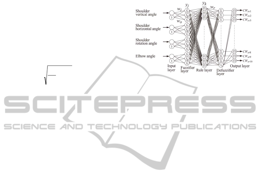
The neuro-fuzzy modifier for the shoulder joint is
shown in Figure 2 as an example. As shown in
Figure 2, the inputs are some joint angles. In
fuzzifier layer, two sigmoid functions and a gaussian
function are used. CW
svi
, CW
shi
, CW
sri
which are the
outputs of neuro-fuzzy modifier are the gains for
each initial weight value. The weight values in eq.
(2) are calculated by multiplying the gains with the
initial weight values. In the neuro-fuzzy modifiers,
the weight value is learned for each user before
operation using the error back propagation learning
algorithm.
3.2 Motion Estimation by using EEG
Signals
Figure 2: Neuro-fuzzy modifier for shoulder joint.
The raw EEG signals are also not suitable as input
signals of the wearable robots such as power-assist
robots. Hence, some features must be extracted from
the raw EEG signals in order to use the EEG signals
as input signals for those robots. There are many
kinds of methods to extract the features of EEG
signals. For example, the averaging method and the
fast Fourier transformation (FFT) are basic methods
to treat EEG signals on offline analysis. Because
those methods require a lot data of EEG signals, in
general, those methods are not suitable for the real-
time control method. In this paper, to extract the
feature of the raw EEG signals, band pass filter
(BPF) is used at first. Since relatively-low frequency
in EEG signals contains the important feature of the
motion and they are used instead of alpha wave or
beta wave in order to estimate the hand velocity in
some methods (Lv et al., 2010), (Bradberry et al.,
2010), the frequency between 0.3 and 4 Hz is used
in the method. The hand velocity is estimated from
the EEG signals after the BPF with 0.3-4Hz. In
general, electrodes are located based on International
10-20 system. On the other hand, in this study, we
can measure 256 EEG signals. However, the EEG
signals of 256 channels are too many, and all of
them are not required as input signals for the
controller. Therefore, 40 important EEG channels
are selected from 256 channels. In 256 channels, 61
electrodes are located on the cheeks and bottom of
the head. Since those electrodes might detect other
signals such as EMG signals except EEG signals,
they are excluded from the channel selection
preliminarily. To select the channels of EEG signals,
at first, we measure EEG signals as the pre-
experiment. In the pre-experiment, the subjects
perform the various motions of upper-limb. After
BPF processing, an angle between two EEG signal
EstimationofUser'sMotionIntentionofHandbasedonBothEMGandEEGSignals
449

vectors is calculated based on inner product as
follows.
ji
ji
ij
VV
VV
cos
(3)
where V
i
= [v
i0
v
i1
··· v
iN
]
T
represents the vector
which consist of EEG signals of ith channel (N is the
time count), θ
ij
is the angle between vector V
i
and
vector V
j
, and <·> represents inner product. If vector
V
i
is perpendicular to vector V
j
, inner product and
cosθ
ij
between V
i
and V
j
become zero. On the other
hand, if V
i
is nearly parallel to V
j
, inner product
between V
i
and V
j
has a certain value that is not
equal to zero, and absolute value of cosθ
ij
becomes
almost one. The sum of cosθ
ij
becomes smaller if V
i
is becoming perpendicular to the other vectors.
Therefore, the evaluation E
1i
function is defined as
follows.
195
1
1
cos
k
iki
E
(4)
The first channel in which E
1i
becomes a minimum
value is selected. After that, channels are selected
based on the evaluation E
2i
function as follows.
s
N
k
kini
E
1
][2
cos
(5)
where n[k] is the array which consists of the selected
channels. N
s
is the number of selected channels. The
channel which E
2i
becomes a minimum value among
non-selected channels is selected. Then the selected
channel number is added to array n[k] and N
s
is
increased until N
s
becomes 40. The channels which
are becoming near perpendicular to the already
selected channels are selected by using eq. (5). The
examples of the selected electrode’s locations are
shown in Figure 3. In Figure 3, red circles represent
the selected channels based on eqs. (4) and (5). Note
that the selected channels are different between each
subject as shown in Figure 3. After the selection of
the EEG channels, the average values of EEG
signals are calculated as follows in order to extract
the feature.
t
a
Ntk
ik
a
itavg
v
N
v
1
,
1
(6)
where v
it
represents the EEG signals of ith channel
after filtering at tth sampling, and N
a
is the sampling
number (N
a
=200). v
avg,it
represents the EEG signals
of ith channel after calculation at tth sampling. A
neural network is used to estimate a user’s hand
Figure 3: Example of selected channels.
motion from EEG signals. The neural network
which estimates a user’s hand velocity consists of
three layers (input layer, hidden layer, and output
layer). There are 40 neurons in the input layer, 100
neurons in the hidden layer and 6 neurons in the
output layer. v
avg,it
is used as input signals to estimate
the user’s hand velocity. The error back propagation
learning algorithm has been applied to train the
neural network. A nonlinear sigmoid function is
used as the activation function for the neurons in the
hidden layer.
3.3 Motion Estimation by using EMG
and EEG Signals
The EMG signals that are needed to estimate the
motions of a human upper-limb are not always able
to measure from all users. Therefore, The EMG and
EEG signals are used to estimate the upper-limb’s
motion of a user. In this study, the EMG signals are
used as main input signals because the EMG signal
has straightforward relationships with the
corresponding muscle. In addition, the EEG signals
are used as sub signals to cover the estimation of the
user’s motion intention.
In the case that a user can measure the all EMG
signals which are needed to control the upper-limb
power-assist robot, the hand force vector which
represents the user motion intention is calculated as
follows.
τJF
T
hand
(7)
where
τ is the joint torque vector, J is the Jacobian
matrix, and
F
hand
is the hand force vector. On the
other hand, if the EMG signals which are needed to
control the robot cannot be measured, a part of joint
torques of upper-limb is not able to calculate by
using eq. (2). In this case, the hand force vector is
expressed as follows.
ICINCO2013-10thInternationalConferenceonInformaticsinControl,AutomationandRobotics
450

Figure 4: Experimental condition.
rppremghand
FτJFFF
T
(8)
where
F
emg
is the part of the hand force vector which
can be calculated by the EMG signals,
τ
p
is the joint
torque vector in which each joint torque can be
estimated by the measured EMG signals,
J
p
is the
Jacobian matrix for
τ
p
. F
r
is the part of the hand
force vector which cannot be calculated by the EMG
signals. Then, the hand velocity is calculated based
on
F
hand
.
remghandhand
FFMFMa
11
(9)
remg
remghandhand
dtdt
vv
FFMav
1
(10)
where a
hand
and v
hand
are the hand acceleration and
velocity vectors, respectively.
M is the mass matrix.
In eq. (10),
v
emg
is estimated based on EMG signals.
In the case of the estimation of
v
r
by using the EMG
and EEG signals, the part of the direction of the
hand velocity is estimated based on the neural
network as the same way in section 3-B. In the case
of section 3-B, the input layer of the neural network
has 40 neurons (the number of selected EEG
channels). In contrast, in the case of estimation
based on EMG and EEG signals, the number of
neurons of input layer is equal to the number of
selected EEG channels (40) and the number of joint
torques which can be estimated by the EMG signals.
After the estimation of the direction of hand velocity,
v
r
in eq. (10) is defined so that the resultant torque of
the absolute values of each joint torque which
cannot be estimated by the EMG signals becomes
minimum value.
4 EXPERIMENT
To verify the effectiveness of estimation method, the
experiments were carried out. In the experiments,
the subjects wore the 7-DOF upper-limb power-
assist robot Kiguchi et al., 2012) and performed
some combined motions of upper-limb. The power-
assist robot has encoders and potentiometers in order
to measure each joint angle. Therefore, we can
calculate the position and orientation of the subjects’
hand based on each joint angle. In the experiments,
the robot just followed the subject’s motion and did
not perform the power-assist. The EMG and EEG
signals of the subject were measured during the
upper-limb motions. The subjects were healthy
young men who can measure all EMG signals (16
channels). The experimental condition is shown in
Figure 4. In the estimations, we assume that some
EMG signals of the subjects could not be measured,
and estimate the hand motion intention by using the
EEG and the remaining EMG signals.
In the first case, we assume that EMG signals of
ch.11 and ch.12 cannot be measured. Those two
channels are difficult to find the correct locations of
electrodes. In this case, although the robot can
estimate the torques of 6 joints, the robot cannot
estimate the torque of the subject’s forearm if the
input signals are only EMG signals. Therefore, the
EMG and EEG signals are used for the estimation.
The example of estimation results is shown in Figure
5. Figure 5 shows the hand velocities. The black line
is the result which is estimated based on 16 EMG
signals (Only EMG case), the red line is the result
which is estimated based on 14 EMG signals and
EEG signals (EMG and EMG case). In the case of
Figure 5, the subject moved the elbow joint and the
forearm mainly. The origin of the coordinate frame
in Figure 5 is shoulder joint. x axis is the
dorsoventral axis, y axis is dorsoventral axis, and z
axis is the craniocaudal axis. From Figure 5, the
estimation results by the EMG and EEG signals
represent the subject’s motion.
In the second case, we assume that EMG signals
from ch.11 to ch.16 cannot be measured. This
assumption means that a user is above elbow
amputee. In this case, forearm and wrist motions
cannot be estimated based on only EMG signals.
Figure 6 shows the estimation results. The subjects
performed the motion to carry a cup to mouth to
drink water. Compared with Figures 5 and 6, the
case of Figure 6 is worse than the case of Figure 5
because less EEG signals are able to be measured in
the case of Figure 6. From Figure 6, although there
are some difference between the estimation result
and the subject’s motion, the subject’s motion is
described on some level by estimating based on
EMG and EEG signals.
EstimationofUser'sMotionIntentionofHandbasedonBothEMGandEEGSignals
451
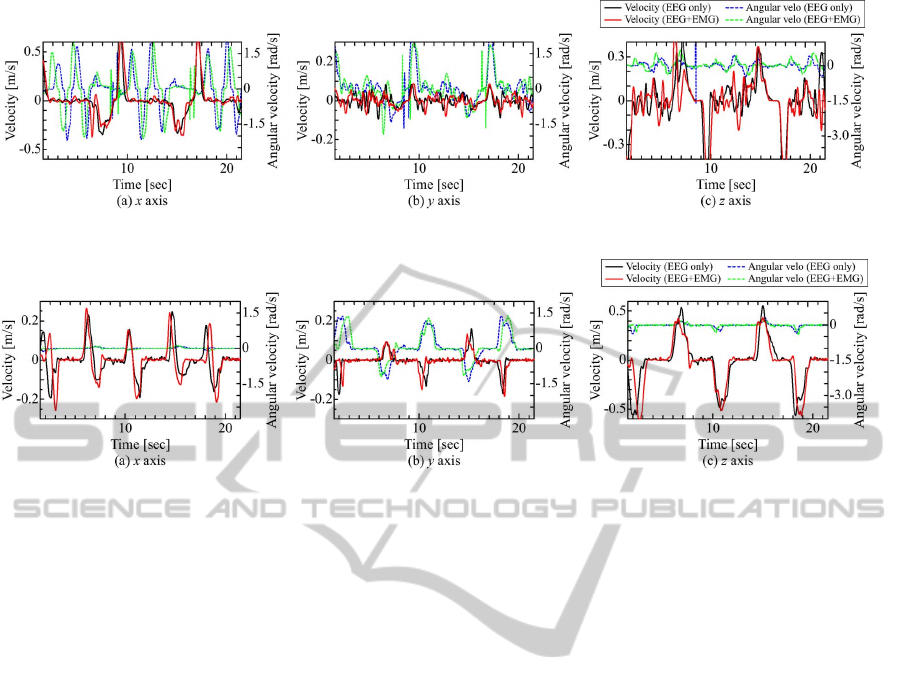
Figure 5: Experimental results (first case).
Figure 6: Experimental results (second case).
5 CONCLUSIONS
A surface EMG signal is one of the most widely
used signals as input signals for wearable robots.
However, EMG signals that are needed to estimate
the motions of a human upper-limb are not always
available to every user. On the other hand, in the
case of an EEG signal, the measured EEG signal
does not have straightforward relationships with the
corresponding brain part. Therefore, it is more
difficult to find the necessary signals for the control
of the robot compared with the EMG signals. In this
paper, we use the EMG and EEG signals as input
signals for wearable robots, and estimated the user’s
motion intention of the upper-limb based on the
measured EMG and EEG signals. The EMG signals
are used as main input signals because the EMG
signals have higher relative to the motion of a user
in comparison with the EEG signals. The EEG
signals are used as sub signals in order to cover the
estimation of the user’s motion intention when all
required EMG signals cannot be measured. The
experimental results show the effectiveness of the
estimation method.
ACKNOWLEDGEMENTS
This work was partially supported by Japan Society
of Promotion of Science (JSPS) Grant-in-Aid for
Scientific Research (C) 23560293.
REFERENCES
C. J. Yang, et al., 2008. A review of exoskeleton-type
systems and their key technologies. Proc. of IMechE,
Journal of Mechanical Eng. Science, Part C.
A. B. Zoss, et al., 2006. Biomechanical Design of the
Berkeley Lower Extremity Exoskeleton (BLEEX).
IEEE/ASME Trans. on Mechatronics, 11(2).
H. Kobayashi, et al., 2004. Realization of all 7 motions for
the upper limb by a muscle suit. Journal of Robotics
and Mechatronics, 16(5).
A. Z. Escudero, et al., 2002. Development of a parallel
myoelectric prosthesis for above elbow replacement.
Proc. of the Second Joint EMBS/BMES Conf.
Q. Novi, et al., 2007. Sub-band Common Spatial Pattern
(SBCSP) for Brain-Computer Interface. Proc. of 3rd
Int. IEEE EMBS Conf. on Neural Eng.
G. E. Fabiani, et al., 2004. Conversion of EEG activity
into cursor movement by a brain-computer interface
(BCI). IEEE Trans. on Neural Systems and Reha. Eng.,
12(3).
J. Lv, et al., 2010. Decoding hand movement velocity
from electroencephalogram signals during a drawing
task. BioMedical Eng. OnLine, 9:64.
T. J. Bradberry, et al., 2010. Reconstructing Three-
Dimensional Hand Movements from Noninvasive
Electroencephalographic Signals, The Journal of
Neuroscience, 30(9).
K. Kiguchi, et al., 2012. An EMG-Based Control for an
Upper-Limb Power-Assist Exoskeleton Robot, IEEE
Trans. Systems, Man, and Cybernetics, Part B, 42(4).
ICINCO2013-10thInternationalConferenceonInformaticsinControl,AutomationandRobotics
452
