Surface Cleaning Force Control of Rotating Brushes
for an Air Duct Cleaning Robot
Wootae Jeong
1
, Seung-Woo Jeon
2
, Duckshin Park
1
and Soon-Bark Kwon
1
1
Eco-Transport Research Division, Korea Railroad Research Institute,Gyeonggi-do,Uiwang, Korea
2
Department of Virtual Engineering, University of Science and Technology, Daejeon, Korea
Keywords: Force Control, Compliance Device, Kinematic Analysis, Service Robot, Air Duct Cleaning.
Abstract: Due to the complexity of the air duct and ventilation system, removing accumulated dusts and particular
matters at inner surface of air duct system becomes key issue for improving indoor air quality and
maintaining the green environment of underground facilities. Although various tools and technologies for
air duct cleaning have been developed, mechanical brushing method is evaluated as the most effective
method in cleaning duct and ventilation system. Therefore, automotive duct cleaning robot with rolling
brushes has been developed in this study. In particular, by adding compliant force feedback sensors to the
rolling brushes, the developed cleaning robot can control the cleaning force consistantly between brush and
duct surface. Force feedback control algorithm has been also developed and evaluated through control
simulation tools.
1 INTRODUCTION
The HVAC(Heating, Ventilating, and Air
Conditioning) system that supplies fresh and clean
air from outdoor environment has been utilized in
most of closed spaces such as modern buildings and
subway facilities where people work and spend most
of their daily hours. Due to the complexity of the air
duct and ventilation system and long period of
cleaning and maintenance, various types of
infiltrated particles and dusts are accumulated at
inner surface of the duct without being exhausted.
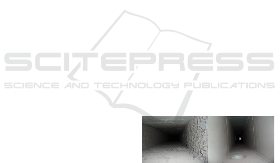
Figure 1 shows pictures of before and after cleaning
duct. In general, the accumulated dusts and particles
flow into the living space and influence on the
human respiratory system and health. In addition,
the accumulated dusts and particles can reduce the
efficiency of the air conditioning and heating of the
HVAC system reported by Brosseau et al., 2000
Furthermore, the closed structure of ducts provides a
good propagating circumstance of microorganisms
including viruses and bacteria. Recently some
contraries have established the regulation and
guideline for ventilation system cleaning (FiSIAQ,
2001), however, many countries still do not have
legal regulations about cleaning ventilation systems.
Recently, the research and development of duct
Figure 1: Before cleaning Air duct and After Cleaning.
cleaning technology has been conducted widely as
concerns and requests of improving air quality are
increasing. In fact, duct cleaning techniques can be
classified as a dry method such as blowing out with
compressed air and scraping out using mechanical
brush and a wet method spraying water or chemical
solution. Especially, the mechanical brushing is
widely used because of its higher cleaning efficiency
and accessibility. Various types of robots with
mechanical cleaning tools have been developed and
used for specific air duct cleaning. However, many
manual cleaning methods are still broadly being
used in cleaning the HVAC systems.
Therefore, in order to provide more efficient and
autonomous mobile cleaning robot platform, a new
mobile robot equipped with mechanical rotating
brushes and sensors has been developed as shown in
Figure 2. In particular, the duct cleaning robot can
clean four sides of inner duct surface simultaneously
453
Jeong W., Jeon S., Park D. and Kwon S..
Surface Cleaning Force Control of Rotating Brushes for an Air Duct Cleaning Robot .
DOI: 10.5220/0004591104530457
In Proceedings of the 10th International Conference on Informatics in Control, Automation and Robotics (ICINCO-2013), pages 453-457
ISBN: 978-989-8565-71-6
Copyright
c
2013 SCITEPRESS (Science and Technology Publications, Lda.)
and utilize spring-based force feedback compliant
device to be adapted at irregular cleaning target
surfaces of ducts.
In this paper, a force feedback control method is
suggested to keep the constant cleaning brush
pressure on the irregular duct surface with simple
spring-based compliant devices. In addition, various
simulations have been conducted to evaluate
performance of the control method.
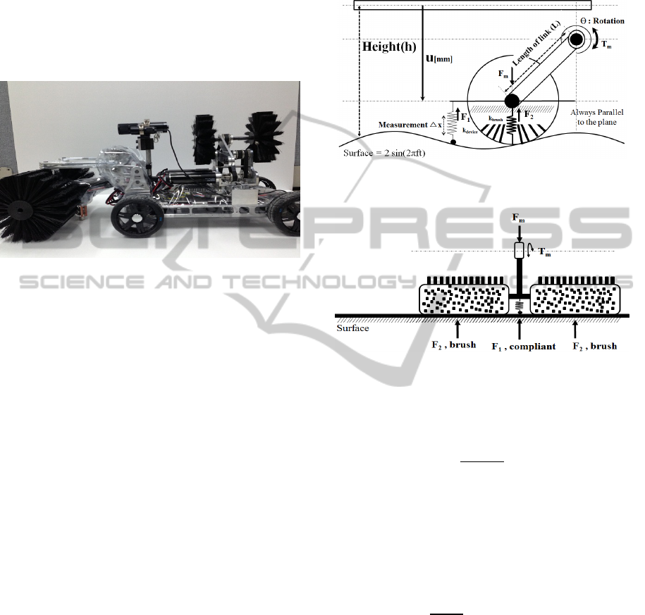
Figure 2: Prototype of Duct Cleaning Robot.
2 FORCE CONTROL USING
COMPLIANT DEVICE
The pressing force of the rotating brush acting on the
surface of the duct should be sustained constantly to
remove the dusts accumulated firmly on the duct
surface through many years. Higher cleaning
pressure can damage duct surfaces and lower
cleaning pressure may not be enough to remove the
firmly attached dust and contaminants on the duct
surfaces. Therefore, it is important to control the
pressing force of the rotating brush constantly with
respect to irregular surface of inner duct. This
section describes modelling and control of the
rotating brush with a spring-based force compliant
device.
2.1 Modelling of the Mechanical Brush
The compliance device is composed of the linear
spring, linear encoder and ball roller attached at the
end of the spring not to resist for moving with
rotating brush of the robot platform. Figure 3 shows
the free body diagram of the robot arm pressing the
brush to the surface of the duct. Figure 4 illustrates
the forces acting on the surface and brushes. In this
model, only the normal forces to the surface are
considered and tangential force including the friction
force of the surface is neglected. Spring constant of
the compliant device is considered as relatively very
small compared to the elasticity of the brush, which
can also ignore the extra effect for measuring force
caused by the device.
Figure 3: Free Body Diagram of the rotating brush of the
robot arm contacting the surface of the duct.
Figure 4: Frontal View of force equilibrium of pushing the
brush and elastic forces of compliant device and brush.
The force acting on the robot arm(F
m
) can be
expressed by
(1)
where
: the motor torque,
N : gear reduction ratio,
L : effective length of the link.
From Figure 4 the motor torque can be calculated
from the force equilibrium equation given by
2
(2)
T
Lsin
θ
N
F
2F
(3)
where
∆,
.the Δx is a
spring deformation, k is a spring constant of the
compliant device, and
is assumed as the 2
nd
order
displacement of spring by pressing.
Since the actual characteristic of the stiffness of
the brushes shows nonlinear behaviour against
external force, the stiffness of the rotating brush has
been modelled as 2
nd
order polynomial function.
Therefore, simple nonlinearly elastic characteristic is
used to reveal feasibility of the force control with the
ICINCO2013-10thInternationalConferenceonInformaticsinControl,AutomationandRobotics
454
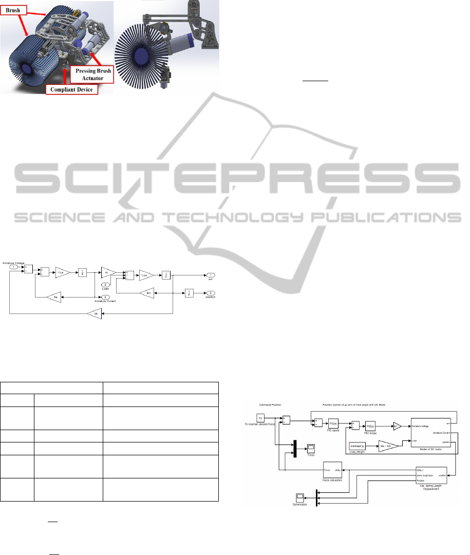
spring deformation feedback. Figure 5 shows the
prototype of the robot arm brush with a compliant
device to measure the deformation of the spring.
Figure 5: Modelling of Robot arm brush with compliant
device.
2.2 Motor Dynamics and Control
The simple DC motor dynamic model shown in
Figure 6 is used in simulation with MATLAB
®
SIMULINK
®
tool. The model is consisted of linear
differential equations of mechanical and electrical
system summarized at Eq.(4) and Eq.(5). Each
motor parameter and values are summarized in
Table 1.
Figure 6: Motor Dynamic Model implemented by
MATLAB
®
SIMULINK
®
.
Table 1: DC Motor Specification.
Parameter Value
Rotor inertia 10.8 g
B
Speed/Torque
gradient
40.3 rpm/mNm
Torque Constant 23.4 mNm/A
Speed Constant 408 rpm/V
Terminal
Inductance
0.238 mH
Terminal
Resistance
2.32 Ω
1
(4)
w
t
l
(5)
(6)
(7)
where
Load from the end of the motor axis,
is
torque proportional to the current
, and
is back
electro-motive force from the coil of the motor
The rotation angle of the motor
is
obtained from angular velocity of
. The load
value for the DC motor is also induced from the
weight of the robot arm brush. Therefore, the torque
generated by the motor Eq.(3) can be calculated as
following
2
(8)
where
: the motor torque,
N : gear reduction ratio,
L : effective length of the link,
M: mass of the robot arm linkage.
2.3 Force Control
Based on the Hooks Law of the spring-based
compliant device, the force of the compliance can be
calculated from the deformation generated by the
brush(robot arm) moving vertically. The relationship
between the position of the brush and deformation of
the spring can be expressed as follows
∆x l
Heightu
(9)
0.1480.002sin2πft
(10)
where
is the initial length of the spring and u is
vertical position of the brush.
The Height variable was defined as the length
from the top of the duct. The irregularity of duct
surface was modelled with sinusoidal function and
sensing disturbance was also added to the control
model shown in Figure 7. Finally, the Figure 7
illustrates the dynamic model of the force control of
the brush with the compliant device.
Figure 7: Force control model with deformation feedback.
The force control model has been simulated with
PID control gains as summarized in Table 2. Figure
8 shows the schematic diagram of the robot control
system including host computer and communication.
SurfaceCleaningForceControlofRotatingBrushesforanAirDuctCleaningRobot
455
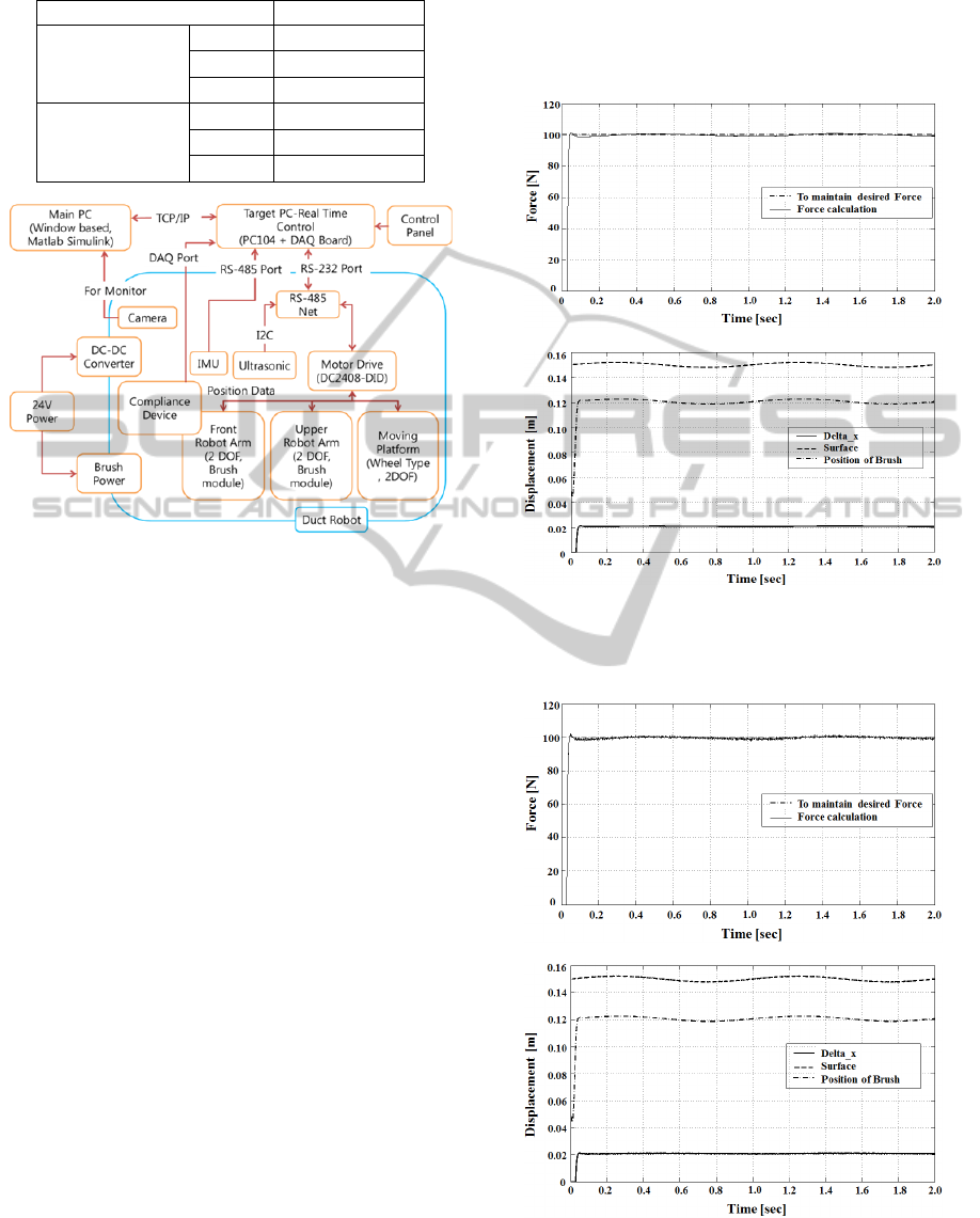
Table 2: PID Gains for Force Control of Robot Arm.
Gain
Value
Speed control
P
2.114
I
8.853
D
-0.002
Torque control
P
0.166
I
11.807
D
0
Figure 8: Schematic diagram of the robot control system
and communication.
3 SIMULATION RESULTS
The spring constant (k) of the compliant device used
in the simulation is 0.3[N/m], and coefficients for
the nonlinear brush stiffness is assumed as values of
a=2000[N/m
2
], and b=4500[N/m], which is
expressed in the Eq.(2). It is also considered that the
maximum allowable displacement of the spring to
the geometry including the diameter of the brush is
100mm and the height of the duct is 150mm. The k
is exerted by that of value installed to the prototype
robot. However, constants of the nonlinear stiffness
brush are decided arbitrary which is relatively higher
than that of compliant spring. At first, the simulation
results are shown in Figure 9 controlling the force
from deformation feedback to satisfy the desired
force by moving the brush on the sinusoidal surface.
Figure 9(a) shows the result of force control that
of maximum error is 1% to the objective force and
the spring is deformed below the limit (0.05m) of
the geometric interference.
Next, the sinusoidal surface function is changed
by adding disturbances signal whose maximum level
is 1/25 of the magnitude of sinusoidal function.
Results are presented in Figure 10. The error bound
is 1N similar to that of previous results shown in
Figure 8(a). The Pressing force of the brush has been
controlled with the spring-based force compliant
device whose results are depicted in Figure 9, and 10.
In addition, the nonlinear behaviour of the brush
stiffness has not been considered, that is, the brush
stiffness has been modelled as a linear spring.
(a)
(b)
Figure 9: Results of Force Control at 2mm, 1Hz sinusoidal
function of Surface. (a) Measured Force, (b)
Displacement.
(a)
(b)
Figure 10: Results of Force Control at 2mm, 1Hz
sinusoidal function with 1/25 disturbances of Surface. (a)
Measured Force, (b) Displacement.
ICINCO2013-10thInternationalConferenceonInformaticsinControl,AutomationandRobotics
456

4 CONCLUSIONS
In this study, the cleaning force control of the
rotating brush has been conducted by utilizing the
spring-based simple compliant device. It is also
assumed that the stiffness of the brush is modelled as
nonlinear function with 2
nd
order polynomials about
displacement to reflect nonlinear characteristics of
the brush. In results, the cleaning force can be
successfully controlled with the simple compliant
device. In future study, some simplifications and
assumptions such as tangential force on the surface
can be partially considered for more accurate results.
Furthermore, it is also necessary to consider
dynamic model of rotating brush. The simulation
results will be further verified under the test-bed
environment using the prototypes of the duct
cleaning robot.
ACKNOWLEDGEMENTS
This research has been conducted as a part of the
subway air duct cleaning robot project (Eco-
Innovation, No. E211-40002-0003-0) partially
funded by the Ministry of Environment in Korea.
REFERENCES
Brosseau, L. M., Vesley, D., Kuehn, T. H., Melson, J.,
Han, H.S. 2000. ‘Duct cleaning: A review of
associated health effects and results of company and
expert surveys’, ASHRAE Trans, 106, 180-187.
Finnish Society of Indoor Air Quality and Climate
(FiSIAQ). 2001. Classification of indoor climate 2000,
Espoo, Finland.
Jeong, W., Jeon, S. W., Park, D., Kwon, S. B., 2012.
‘Force Control of a Duct Cleaning Robot Brush Using
a Compliant Device, 10
th
International Conference on
Informatics in Control, Automation and
Robotics(ICINCO) 2012, Roma, Italy.
Robotics Design, ANATROLLER ARI-100, http://
www.roboticsdesign.qc.ca/mobile-robots, Canada.
Wang, Y., Zhang, J., 2006. ‘Autonomous Air Duct
Cleaning Robot System,’ Proc. of International
Midwest Symposium on Circuits And System, pp. 510-
513, 2006.
Motor Specification, RE ∅25mm, Graphite Brushes, 20W,
http://www.maxonmotor.com/maxon/view/product/mo
tor/dcmotor/re/re25/118752, Switzerland.
Kim, S.H. 2007. ‘Control of DC and AC Motor’. Buk-du
Press, Seoul: 96-103.
SurfaceCleaningForceControlofRotatingBrushesforanAirDuctCleaningRobot
457
