
Multi-source Energy Harvesting Powered Acoustic Emission Sensing
System for Rotating Machinery Condition Monitoring Applications
Wensi Wang
1
, Anderson Machado Ortiz
2
, Ningning Wang
1
, Michael Hayes
1
, Brendan O’Flynn
1
and Cian O’Mathuna
1
1
Tyndall National Institute, Dyke Parade, Cork, Ireland
2
Department of Energy, Fundaci
`
o CTM Centre Tecnol
´
ogic, Manresa, Barcelona, Spain
Keywords:
Acoustic Emission Sensor, Wireless Sensor System, Preventive Maintenance, Energy Harvesting.
Abstract:
This study concerns with the acoustic emissions (AE) monitoring for the applications of rotating machine fault
detections. The first prototype wireless AE sensor system with vibrational, thermal and light energy harvest-
ing power supply is presented in this paper. This prototype regularly records the AE signal at 150-250KHz
frequency bandwidth and compares with known gear/bearing fault patterns. The data are compressed and
transmitted via Zigbee based wireless transceiver to nearby central control unit. The multiple-source energy
harvester proposed in this work generates 1.56mW from 0.048g vibration energy and 3.37mW thermoelectric
energy when deployed on the 62
o
C metal surface of a gas compressor. This battery-less wireless AE system
achieves power autonomy from environmental energy, realizing a self-powered easy-to-deploy wireless data
transmitting based health monitoring solution for wide range of rotating machinery.
1 INTRODUCTION
Rotating machinery such as electric motor, turbine
and air compressor are widely equipped in great many
industries, such as general manufacturing, power gen-
eration, refrigeration and many others. In rotating
machinery, gear and bearing are critically important
components. They are required to operate with high
reliability for extended period of time in harsh envi-
ronmental conditions. Unexpected Faults (UFs) of
the gear and bearing may lead to damages of entire
machine. Consequently, these UFs will cause consid-
erable machine repair/replacement cost, and also the
associated labour and downtime costs. Therefore, pe-
riodic non-destructive testing (NDT) and on-line con-
dition monitoring (OCM) are often used to conduct
preventive maintenance (PM) in order to effectively
diagnose and prevent further development of faults
(Bastianini et al., 2013).
Since early 2000s, the method of Acoustic Emis-
sion Monitoring (AEM) has been proposed for PM
applications (De Silva, 2010) and (Bohse, 2013).
Acoustic Emissions (AE) in rotating machinery are
transient elastic waves produced by the interactions
of two media of gears/bearings in relative motions.
AEM methods “listen” to and process the elastic wave
signals and used the interpreted information to di-
agnose the potential faults in the early stage of sur-
face/subsurface crack formation.
The evolution of wireless sensor networks (WSN)
technologies in the last decade provides an unique op-
portunity for the further development of NDT systems
(Grosse and Kr
¨
uger, 2006). The micro-controller
(MCU) and low-power wireless transceiver based
WSN module (mote) is substantially less expensive
and less power-hungry than the conventional pro-
grammable logic controller (PLC) and Modbus se-
rial communication based monitoring system. In ad-
dition, the battery powered WSN can be deployed
with minimal installation cost. WSN based AEM
system has been proposed for infrastructure (bridges
and buildings) structural health monitoring applica-
tions (Ledeczi et al., 2009) and (Ayg
¨
un and Gungor,
2011).
However, a bottleneck of WSN development is the
limited battery energy. The 0.5 milliwatts ultra-low
power WSN system can only achieve 6-month bat-
tery lifetime when powered from 1000mAh battery in
optimal condition. The task to regularly replace bat-
tery can become expensive when the number of WSN
motes is large and even impossible when the mote is
placed in difficult-to-access locations.
Energy harvesting technologies provide a feasible
solution for WSN mote power supply. This method
492
Wang W., Machado Ortiz A., Wang N., Hayes M., O’Flynn B. and O’Mathuna C..
Multi-source Energy Harvesting Powered Acoustic Emission Sensing System for Rotating Machinery Condition Monitoring Applications.
DOI: 10.5220/0004593804920499
In Proceedings of the 10th International Conference on Informatics in Control, Automation and Robotics (ICINCO-2013), pages 492-499
ISBN: 978-989-8565-70-9
Copyright
c
2013 SCITEPRESS (Science and Technology Publications, Lda.)

“harvests” various forms of environmental energy
such as vibration (Zhu et al., 2012a), thermoelectric
(Im et al., 2012) and solar/light (Wang et al., 2012)
into electricity to power WSN mote. The power man-
agement circuity of energy harvester stores the energy
in electric double-layer capacitor (supercapacitor) or
thin film solid state battery and utilizes the energy
when needed. The utilization of the small but “infi-
nite” ambient energy provides a potentially indefinite
battery lifetime for WSN systems. Recently the con-
cept of multiple sources energy harvesting has been
proposed to harvest energy from more than one type
of energy (Weddell et al., 2013).
Figure 1: Energy Harvesting Powered Wireless AEM Mod-
ule for Gas Compressor Monitoring.
By integrating and optimizing the three key tech-
nologies: 1) AE sensing, 2) Wireless sensor system,
and 3) Energy harvesting, a new type of machinery
preventive maintenance system is proposed. This pa-
per introduces a vibration/thermoelectric/light pow-
ered wireless sensor module based acoustic emission
monitoring system for rotating machinery fault detec-
tion application. Fig.1 illustrates the application of
this proposed system in gas compressor monitoring.
The remainder of this paper presents the working
principal, prototype implementation and the prelimi-
nary results of the proposed system. Section 2 sum-
marizes related work in the area of machinery moni-
toring and energy harvesting powered WSN systems.
Section 3 introduces the system architecture and sub-
systems. The first part of Section 4 presents the AE
sensor and related signal processing. The rest part of
Section 4 shows the multiple-source energy harvest-
ing system and power management circuits. Section
5 demonstrates the prototype implementation and the
preliminary test results as of April 2013. Final section
concludes the main findings and planned future work.
2 RELATED WORK
The concept of rotating machinery monitoring has
been addressed in many publications and and im-
plemented in many commercial products. The most
widely used method of NDT is vibration monitor-
ing (VM) in the past 50 years (McFadden and Smith,
1984), (De Silva, 2010). More recently, the method
of Acoustic Emission Monitoring (AEM) has been
employed for PM applications. Compared with con-
ventional vibration monitoring methods, AEM shows
several advantages:
a) A substantial drawback of VM is the vibration en-
ergy from other parts of the machine (e.g. shaft
and cooling fan) is often several orders of mag-
nitude higher than the vibration energy of the de-
fect gear and bearing, i.e. low signal to noise ratio
(SNR). Acoustic signal has been proved to have
significantly improved SNR during fault detection
(Bohse, 2013).
b) Since AE sensing is a non-directional/non-contact
technique, AEM system has greater insensitivity
in positioning sensors, which reduces the installa-
tion costs. In addition, fewer sensors are needed
in AEM systems than VM systems (Loutas et al.,
2011).
c) With VM system, when a significant change in vi-
bration can be observed, the remaining lifetime of
the gear/bearing is very short. However, for AEM
system the acoustic emission generated during the
formation of cracks can be detected in the rela-
tively early stage (Mba and Rao, 2006). The ad-
vantage of early detection increases the chance of
preventive maintenance when AEM is employed.
Due to these advantages, AEM technique has been in-
creasingly adopted in recent years for machine and
structure health monitoring applications.
In (L
´
edeczi et al., 2011), Ledeczi et.al. demon-
strates a bridge structural monitoring system with AE
sensors. The DSP unit in this implementation is
based on a FPGA instead of low cost MCU due to
the data processing speed concern in MCU. However,
recent development of MCU towards higher speed
shows that the data process capability can be met by
advanced MCUs such as ARM Cortex-M4 (Rutzig,
2013). Weddell et.al. presented a tunable frequency
electromagnetic transducer powered WSN system for
vehicle ferry engine monitoring application (Weddell
et al., 2012). Since the diesel engine features different
vibration frequency from electric motors, the energy
harvesting device is also different.
Lubieniecki and Uhl presented an work in the area
of harvesting thermal energy from high speed rotating
Multi-sourceEnergyHarvestingPoweredAcousticEmissionSensingSystemforRotatingMachineryCondition
MonitoringApplications
493
bearings(Lubieniecki and Uhl, 2012). It investigated
the correlation between the rotating speed and the har-
vested thermoelectric energy based on their configu-
ration. It has concluded that with a rotating speed of
6000 revolutions per minute, more than 35mW aver-
age power can be harvested from the thermoelectric
generator (TEG).
3 SENSOR SYSTEM
ARCHITECTURE
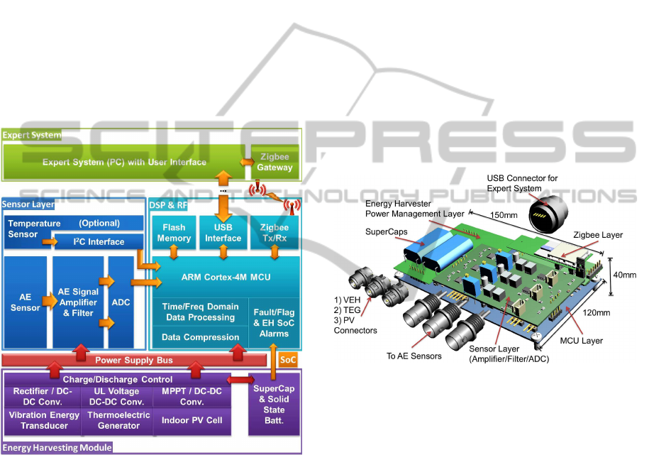
The prototype system block diagram is illustrated in
Fig. 2. The system consists of four main building
blocks: 1) Sensor Layer; 2) DSP & RF Module; 3)
Energy Harvesting Module; 4) Expert System.
Figure 2: Energy Harvesting Powered Wireless AEM Sys-
tem Architecture.
The sensor layer for AE signal sensing includes
AE sensors, amplifier, filter and ADC. It also has a
I
2
C Interface for optional temperature sensors.
The DSP and RF module consists of ARM Cortex-
4M MCU as the DSP unit, NXP JN5148 Zigbee
wireless module for regular RF communication, flash
memory and USB interface. The data processing is
mainly based on fractional Fourier transform (FRFT)
signal process. The results are compared with fault
patterns to “flag” the possible fault. When the fault
pattern is repeatedly detected, an alarm signal is sent
to expert system for further investigation. The pro-
cessed data is compressed and sent to expert system
via the Zigbee module. Flash memory is used to tem-
porarily store the data in the case of unsuccessful RF
data transmission. USB interface is only used during
system maintenance and possible upgrade.
The energy harvesting (EH) module includes 1)
rectifier and DC/DC converter for electromagnetic
(vibration) energy harvester, 2) ultra-low voltage
(UL) DC/DC converter for thermoelectric generator
(TEG), 3) maximum power point tracking (MPPT) for
indoor photovoltaic cells (PV), 4) supercapacitor and
solid state battery (thin film battery) as energy storage
unit (ESU) and 5) charge/discharge control circuity to
conditioning the input/output power from ESU. The
ESU state of charge (SoC) is sent to MCU to monitor
the condition of energy harvester.
The proposed prototype consists of four sub-
system layers as shown in Fig.3 : Energy har-
vester power management layer, Sensor layer (ampli-
fier/filter/ADC), MCU layer and Zigbee communica-
tion layer. Three AE sensors can be connected to this
system.
Figure 3: Energy Harvesting Powered Wireless AEM Sys-
tem Prototype 3D Illustration (the protection case is not
shown in this illustration).
Vibration energy harvester (VEH), thermoelec-
tric energy generator (TEG) and photovoltaic (PV)
cells can be connected to the energy harvester layer.
The main energy storage unit in this implementa-
tion consists of two 5F supercapacitors. The pro-
totype (with IP45 protection case) is measured at
150mm×120mm×40mm. The ingress protection rat-
ing of the case is IP-54. All subsystems have been
prototyped and manufactured as of April 2013.
4 ENERGY HARVESTING
POWERED WIRELESS AEM
SYSTEM DESIGN
The proposed prototype is the first version of the tech-
nology demonstrator. Before the integrating the sub-
systems into the final prototype, each subsystem is de-
ICINCO2013-10thInternationalConferenceonInformaticsinControl,AutomationandRobotics
494
sign and their performance is investigated. This sec-
tion introduces the design of each subsystem.
4.1 AE Sensor System and Signal
Processing
The condition monitoring system is essentially based
on the feature extraction of AE signals. substantial ef-
forts was concentrated on the signal processing of AE
waveforms. Since the “fault pattern” of gear/bearing
is the main diagnostic parameter, long term gear test-
ing was conducted to identify the fault patterns in var-
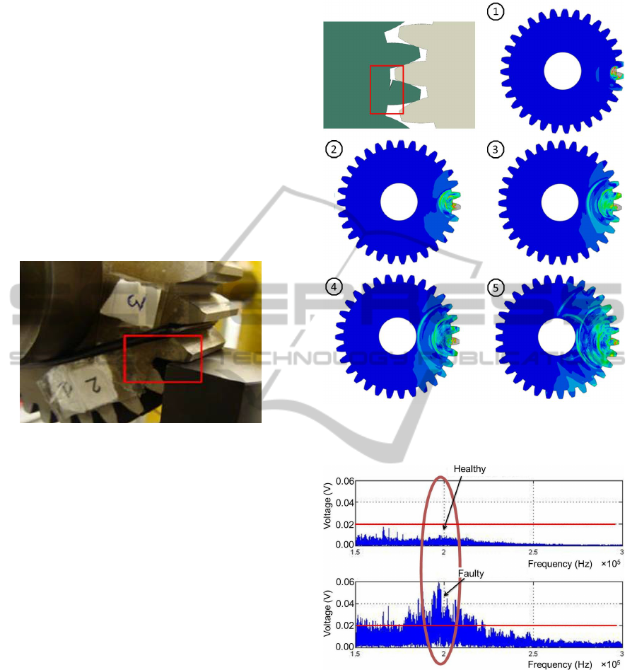
ious frequency bandwidths. Fig.4 shows the test set-
up of the gear surface/subsurface crack formation ex-
periment.
Figure 4: Gear Surface Crack/Wear Acoustic Test Set-up.
The area highlighted in Fig.4 is the root circle of
a gear where the crack most likely to form. The AE
fault pattern tests were conducted with several differ-
ent types and stages of crack formations. A typical
formed crack (late-mid stage) is illustrated and high-
lighted in Fig.5. The gear acoustic emissions test re-
sults are presented when the crack is excited by the
contacts with other gear in Fig.5 (1-5).
Two types of data analysis techniques have been
considered in this work: fractional Fourier transform
(FRFT) and Daubechies wavelet (Grosse et al., 2002).
Whilst the Fourier transform is only localized in fre-
quency domain, wavelets are localized in both time
and frequency domain. Daubechies wavelet with a
10-level signal decomposition may require more data
processing than FRFT (Ching et al., 2004). Fig.6
shows the detected fault pattern at 200KHz when the
late-mid stage of the crack is scanned with a 150KHz-
300KHz filter.
Low power consumption of data processing and
transmission is a main challenge in the design of AE
WSN system. The MCU based device consumes
80-180mW power during “active” mode and 50µW
“sleep” mode power. The power consumption of AE
WSN mote is summarized in Table.1.
Since the harvested power from ambient environ-
ment is at 1mW level, the AE WSN system is pro-
Figure 5: Gear Crack Formation and Acoustic Emissions
Signal When Excited by the Contacts with Other Gear (1-
5).
Figure 6: Gear Fault (crack) Pattern in Frequency Domain
Analysis 150-300KHz FRFT Results.
grammed to perform duty cycling operation (periodic
active-sleep-active cycles) in order to minimize aver-
age power consumption. On average, the active mode
time is approximately 1.37 seconds followed by the
sleep mode time of 1 to 10 minutes in the tests. The
average power consumption ranges from 0.22mW to
1.76mW subject to the operational duty cycles.
Multi-sourceEnergyHarvestingPoweredAcousticEmissionSensingSystemforRotatingMachineryCondition
MonitoringApplications
495
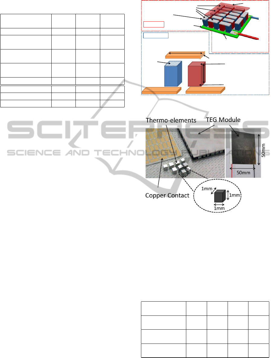
Table 1: Power Consumption of AE WSN Mote (T
S
: sleep
mode time).
AE Power Power Time Energy
Consumption (mW) (Sec) (mJ)
Sleep Mode 0.047 60.00 2.820
Data ACQ 188.1 0.020 3.760
(3 AE Sensors)
Data FRFT & 76.26 0.920 70.16
Compression
Diagnosis 86.16 0.210 18.09
Algorithm
RF Transmission 61.38 0.220 13.50
Total (1min T
S
) 1.760 61.37 108.3
Total (3 mins T
S
) 0.620 181.3 113.9
Total (10 mins T
S
) 0.220 601.3 133.7
4.2 Multiple Source Energy Harvesting
Energy harvesting is proposed in this work to collect
environmental energy and convert the harvested en-
ergy into usable form (Power/Voltage/Current etc.).
On-site experiments had been carried out to investi-
gate the available ambient energy sources in an indus-
trial cold store facility. The mechanical vibration en-
ergy and surface temperatures on various positions of
the main air compressor units (shown in Fig.1) have
been measured to study the “harvest-able” energy. In
this characterization, 0.025g to 0.05g vibration has
been detected in addition to the 60 - 70
o
C surface
temperature on the rotary screw air compressor (near
the air outlet).
Based on the characterization, thermoelectric en-
ergy harvesting is proposed in this work. Thermo-
electric generator is a device that utilizes Seebeck ef-
fect which directly converts temperature difference
into electricity (Ramadass and Chandrakasan, 2011).
Thermoelectric materials high in positive/negative
Seebeck coefficient such as Bi
2
Te
3
are prepared into
P and N types of thermo-elements. One P type and
one N type thermo-elements are then connected in se-
ries via (copper) contacts as shown in Fig.7. In this
configuration the P/N thermo-elements are connected
in parallel from heat transfer perspective and a pair of
thermo-elements forms a thermo-couple.
One thermo-couple can only generate small volt-
age difference (1-2mV) when 50-100
o
C tempera-
ture is applied on the “hot” side of TEG. An array
of thermo-couples are used to form a TEG module
which normally consists of several hundreds thermo-
couples.
Fig.8 shows a Bi
2
Te
3
based TEG module with
P/N type thermo-element measured at approximately
1mm
3
. In this module, 255 thermo-couples are used
Number of Thermo
-couples Pairs N
Height of Ceramic
Substrate L
S
…
Substrate Cold
Side Temp T
C
Substrate Hot
Side Temp T
H
T
H
– T
C
= ∆T
P N
Cross Section
Area A
Length of Thermo-element L
Contact Cross-section
Area A
C
Length of Contact L
C
Thermo-couple
Cold Side Temp T
C
’
Thermo-couple
Hot Side Temp T
H
’
Temperature Difference on Thermo-couple
T’
H
– T’
C
= ∆T’
TEG Module
Thermo-couple
(Copper/gold) Contacts
Figure 7: Thermoelectric Generator (TEG): Thermo-
Couple and TEG Module.
Figure 8: TEG Module.
to form this TEG, connected via copper contacts and
supported with ceramic substrates. This type of TEG
is tested with hot side temperature ranging from 50
o
C
to 80
o
C. Passive heat sink (similar to typical CPU
heat sink) is mounted on the cold side of TEG with
thermal compound applied on the interface between
TEG and heat sink. The measured results of thermo-
electric generator are summarized in Table.2.
Table 2: TEG Characterizations Results at Matched Load.
Heat Source 50 60 70 80
Temp (
o
C)
Module Temp 2.5 4.0 5.5 7.5
Diff. ∆T (
o
C)
Measured 0.212 0.336 0.464 0.632
Voltage (V)
Measured Max. 1.384 3.544 6.704 12.46
Power (mW)
The generated voltage on the load is between
0.212V to 0.632V in this test. This voltage is lower
ICINCO2013-10thInternationalConferenceonInformaticsinControl,AutomationandRobotics
496
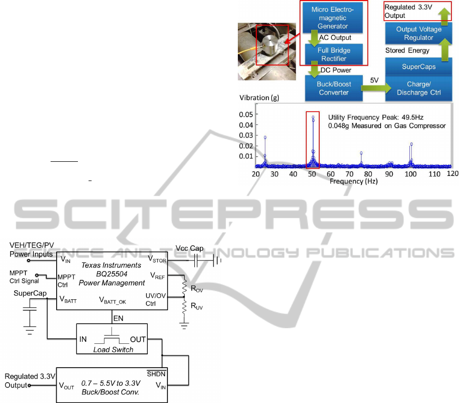
than the minimal start-up voltage of most boost con-
verters. This work adopts a power management de-
sign based on Texas Instruments BQ25504 energy
harvesting chipset. BQ25504 features a start-up volt-
age of 40mV. BQ25504 requires a start-up current of
several mA in order to obtain a 1.8V power supply
voltage on the storage capacitor. A maximum power
point tracking (MPPT) function adjusts the duty cy-
cle of boost converter in order to match the input
impedance of the boost converter to the TEG internal
resistance, thus, a matched impedance. In this work,
an additional load switch and an output voltage regu-
lator (buck/boost converter) are used to supply a reg-
ulated 3.3V voltage output. The load switch and the
enable pin (SHDN) of the buck/boost converter are
controlled by “VBAT OK” pin (Digital battery good
indicator) of BQ25504. In this way, the buck/boost
converter only starts up when BQ25504 is fully oper-
ational. Therefore, the cold start issue of buck/boost
converter can be avoided.
Figure 9: Schematics of Energy Harvester Power Manage-
ment Circuit.
In addition to the thermoelectric energy harvest-
ing, vibrational energy is widely available in the tar-
geted deployment scenarios. In electrical motor sys-
tems, the vibration frequency is highly dependent on
the mains frequency (power line frequency). In this
measurement, as shown in Fig.10, the resonant fre-
quency peaks around 50Hz with 48mg acceleration.
The electromagnetic vibration energy harvester
adopted in this design is Perpetuum FSH module (Zhu
et al., 2012b). The AC power generated from the
energy harvester is rectified by the Perpetuum FSH
module internal full bridge rectifier. The DC/DC
power conditioning of the vibration energy harvester
is also BQ25504. The main difference is the MPPT
circuit is by-passed in this design.
A low voltage indoor photovoltaic power manage-
ment circuit is also built in this design with BQ25504.
Figure 10: Vibration Energy Harvester Power Management
and Measured Vibration of Air Compressor.
Different from impedance match in thermal electric
energy harvesting, the maximum power point voltage
of PV cell is around 76% of its open circuit voltage
(O’Donnell and Wang, 2009). The MPPT control sig-
nal of BQ25504 is adjusted accordingly for the PV
energy harvesting.
The multi-source energy harvester prototype is
implemented and tested on the air compressor unit to
verify the feasibility and functionality of the proposed
design. The energy harvester prototype and its test re-
sults are presented in next section.
5 PROTOTYPE DEPLOYMENT
AND PRELIMINARY RESULTS
The energy harvester for powering AE system pro-
totype was tested on an industrial air compressor in
a large scale cold store facility. Accelerometer and
thermo-couples are used to measure the temperature
and vibration at various part of the air compressor.
The data is recorded using a portable Picolog-1000
data acquisition system with labview interface. The
purpose of this deployment study is to determine the
suitable deployment position of energy harvester for
AE systems. The optimal position where energy har-
vesters can be deployed to is on the air-oil separator
of the air compressor.
The temperature measured on the outlet is mea-
sured at 69
o
C and 62
o
C on the surface of the air-oil
separator. The vibration energy is measured at be-
tween 0.025g and 0.048g at 49.3Hz to 49.7Hz fre-
quency during the experiment (when compressor is
operating). The deployment characterization of en-
ergy harvester is illustrated in Fig.11.
Multi-sourceEnergyHarvestingPoweredAcousticEmissionSensingSystemforRotatingMachineryCondition
MonitoringApplications
497
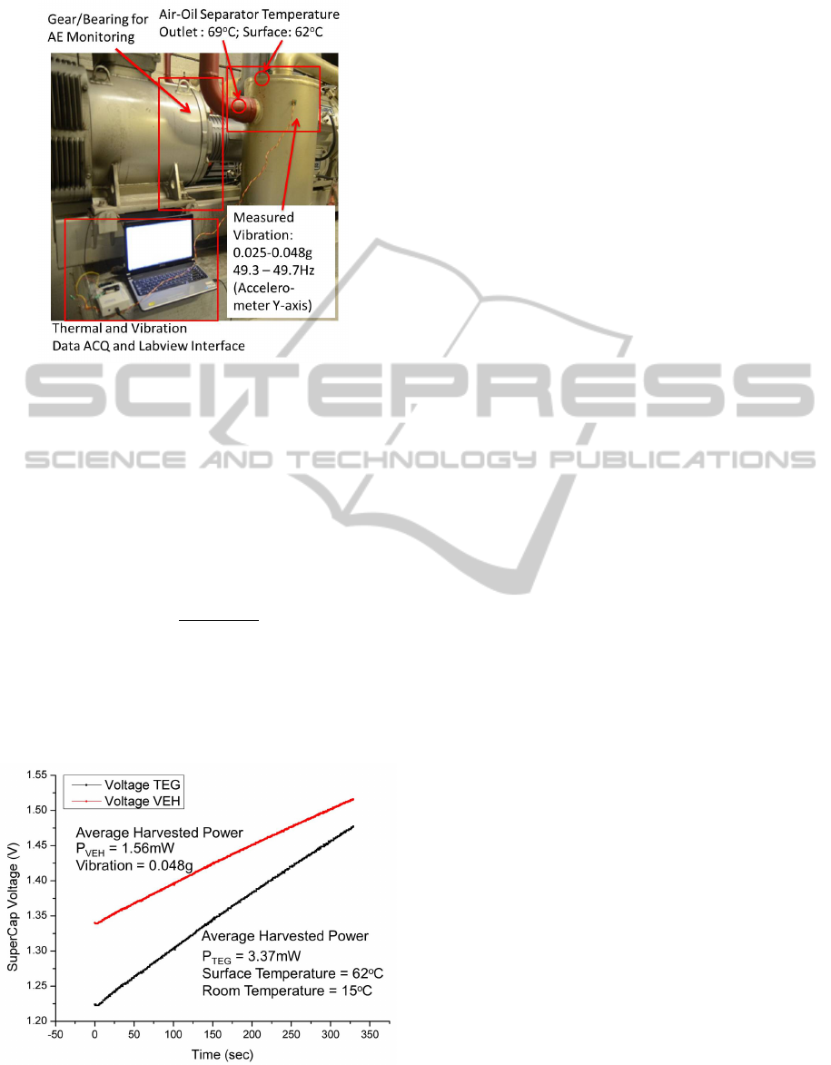
Figure 11: Energy Harvester Powered AE System Deploy-
ment Characterizations.
The energy harvester prototype is then deployed
on the top of air-oil separator. The result verifica-
tion is based on the storage capacitor charging char-
acterization. The thermoelectric and vibrational en-
ergy harvesters are connected to the power manage-
ment circuit in order to charge the 0.47F supercapac-
itor. When charging the capacitive load, the average
charging power P
avg
can be calculated as,
P
avg
=
C
SC
·V
2
target
2 · T
chrg
(1)
where C
SC
is the super-capacitor capacitance, T
chrg
is
the total charging time.
The supercapacitor charging experiments were
conducted on TEG and vibration energy harvester
(VEH). The results are shown in Fig.12.
Figure 12: VEH and TEG Energy Harvesters Supercapaci-
tor Charging Experiments.
The room temperature in the experiment is 15
o
C.
The hot side temperature of air-oil separator is 62
o
C.
The supercapacitor is charged from 1.22V to 1.48V
within 325 seconds. The average harvested power of
TEG is calculated at 3.37mW.
When the VEH is excited with 48mg acceleration
at 49.5Hz, the harvested power charges the superca-
pacitor from 1.34V to 1.52V in 325 seconds. The
harvested vibrational power is 1.56mW on average
during the charging process. The combined harvested
power is calculated at 4.93mW when the air compres-
sor is operational.
By revisiting the power consumption profile of
AE WSN module in Table.1, the harvested power
4.93mW is sufficient to power AE WSN module
to operate with 1 minute measurement intervals
(1.76mW). The minimal measurement interval of AE
WSN module is calculated at 20 seconds, i.e. the
multi-source energy harvester enables the AE WSN
module to perform fault detection every 20 seconds.
6 CONCLUSIONS
Acoustic emissions monitoring system has demon-
strated several advantages over the conventional vi-
bration monitoring system for the application of
gear/bearing fault detections. Micro-controller based
wireless sensor networks (WSN) technologies signif-
icantly reduce the material and installation cost of in-
dustrial monitoring systems. Therefore, an approach
to conduct AE monitoring with WSN modules is pro-
posed in this work.
A main bottleneck for this type of system is
the mote power consumption can deplete the battery
within several months of deployment. An energy har-
vesting subsystem, which can harvest thermal, vibra-
tional and light energy, is then presented in this paper
to power the AE WSN mote with ambient energy.
The feasibility of powering AE WSN mote en-
tirely from energy harvesting is investigated in this
work. When deployed on an air compressor, the pro-
posed power management circuit shows that it can
harvest 3.37mW from wasted heat and 1.56mW from
machine vibration, then store the energy in superca-
pacitor type energy storage unit. The hybrid energy
harvesting subsystem generates 4.93mW when the air
compressor is operational. Based on the AE system
power consumption characterizations, the harvested
power is sufficient to perform AE fault detection ev-
ery 20 seconds and achieves power autonomy in the
air compressor experiments.
All subsystems of the AE WSN system have been
built. The current system is under tests to verify
the reliability in real-world condition. Being a first-
ICINCO2013-10thInternationalConferenceonInformaticsinControl,AutomationandRobotics
498

generation prototype, the prototype device is under-
going an optimization process from power consump-
tion/management, data processing and diagnose algo-
rithm perspectives.
ACKNOWLEDGEMENTS
This work has been funded by European seventh
framework programme (FP7) for small medium en-
terprise under research project Mosycousis (Project
reference number: 285848).
REFERENCES
Ayg
¨
un, B. and Gungor, V. C. (2011). Wireless sensor
networks for structure health monitoring: recent ad-
vances and future research directions. Sensor Review,
31(3):261–276.
Bastianini, F., Sedigh, S., Pascale, G., and Perri, G. (2013).
Cost-effective dynamic structural health monitoring
with a compact and autonomous wireless sensor sys-
tem. In Nondestructive Testing of Materials and Struc-
tures, pages 1065–1070. Springer.
Bohse, J. (2013). Acoustic emission. In Handbook of Tech-
nical Diagnostics, pages 137–160. Springer.
Ching, J., To, A., and Glaser, S. (2004). Acoustic emission
source deconvolution: Bayes vs. minimax, fourier vs.
wavelets, and linear vs. nonlinear. Journal of the
Acoustical Society of America, 115(6):3048–3058.
De Silva, C. W. (2010). Vibration monitoring, testing, and
instrumentation. CRC Press.
Grosse, C. U. and Kr
¨
uger, M. (2006). Wireless acoustic
emission sensor networks for structural health moni-
toring in civil engineering. In Proc. European Conf.
on Non-Destructive Testing (ECNDT), DGZfP BB-
103-CD. Citeseer.
Grosse, C. U., Reinhardt, H. W., Motz, M., and Kroplin,
B. (2002). Signal conditioning in acoustic emission
analysis using wavelets. NDT. net, 7(9):1–9.
Im, J.-P., Wang, S.-W., Ryu, S.-T., and Cho, G.-H. (2012).
A 40 mv transformer-reuse self-startup boost con-
verter with mppt control for thermoelectric energy
harvesting. Solid-State Circuits, IEEE Journal of,
47(12):3055–3067.
Ledeczi, A., Hay, T., Volgyesi, P., Hay, D. R., N
´
adas, A.,
and Jayaraman, S. (2009). Wireless acoustic emis-
sion sensor network for structural monitoring. Sensors
Journal, IEEE, 9(11):1370–1377.
L
´
edeczi,
´
A., V
¨
olgyesi, P., Barth, E., N
´
adas, A., Pedchenko,
A., Hay, T., and Jayaraman, S. (2011). Self-sustaining
wireless acoustic emission sensor system for bridge
monitoring. In New Developments in Sensing Tech-
nology for Structural Health Monitoring, pages 15–
39. Springer.
Loutas, T., Kalaitzoglou, J., Sotiriades, G., and Kostopou-
los, V. (2011). The combined use of vibration, acous-
tic emission and oil debris sensor monitored data com-
ing from rotating machinery for the development of a
robust health monitoring system.
Lubieniecki, M. and Uhl, T. (2012). Thermoelectric en-
ergy harvester: Design considerations for a bearing
node. Journal of Intelligent Material Systems and
Structures, 23(16):1813–1825.
Mba, D. and Rao, R. B. (2006). Development of acoustic
emission technology for condition monitoring and di-
agnosis of rotating machines; bearings, pumps, gear-
boxes, engines and rotating structures.
McFadden, P. and Smith, J. (1984). Vibration monitoring
of rolling element bearings by the high-frequency res-
onance techniquea review. Tribology international,
17(1):3–10.
O’Donnell, T. and Wang, W. (2009). Power management,
energy conversion and energy scavenging for smart
systems. Ambient Intelligence with Microsystems,
pages 241–266.
Ramadass, Y. K. and Chandrakasan, A. P. (2011). A battery-
less thermoelectric energy harvesting interface circuit
with 35 mv startup voltage. Solid-State Circuits, IEEE
Journal of, 46(1):333–341.
Rutzig, M. B. (2013). Multicore platforms: Processors,
communication and memories. In Adaptable Embed-
ded Systems, pages 243–277. Springer.
Wang, W., Wang, N., Hayes, M., O’Flynn, B., and
O’Mathuna, C. (2012). Power management for sub-
mw energy harvester with adaptive hybrid energy stor-
age. Journal of Intelligent Material Systems and
Structures.
Weddell, A. S., Magno, M., Merrett, G. V., Brunelli, D.,
Al-Hashimi, B., and Benini, L. (2013). A survey of
multi-source energy harvesting systems. In Design,
Automation and Test in Europe (DATE).
Weddell, A. S., Zhu, D., Merrett, G. V., Beeby, S., and Al-
Hashimi, B. (2012). A practical self-powered sensor
system with a tunable vibration energy harvester. In
PowerMEMS 2012.
Zhu, D., Beeby, S., Tudor, M., and Harris, N. (2012a). Elec-
tromagnetic vibration energy harvesting using an im-
proved halbach array.
Zhu, D., Roberts, S., Mouille, T., Tudor, M. J., and Beeby,
S. P. (2012b). General model with experimental vali-
dation of electrical resonant frequency tuning of elec-
tromagnetic vibration energy harvesters. Smart Mate-
rials and Structures, 21(10):105039.
Multi-sourceEnergyHarvestingPoweredAcousticEmissionSensingSystemforRotatingMachineryCondition
MonitoringApplications
499
