
Abstract Modeling of embedded Systems Hardware
Christian Hausner and Frank Slomka
Institute of Embedded Systems / Real-Time Systems, Ulm University, 89069 Ulm, Germany
Keywords:
Embedded Systems Design, Cyber-physical Systems, Electronic System Level (ESL), Platform-based Design.
Abstract:
Designing cyber-physical systems is a challenge originating from the multidisciplinary and mixed-signal re-
quirements. In order to handle this challenge, many design languages have been developed, but none covers
the platform-based design and system view well. In this paper we extend our methodology by considering
the aspects of the platform. A new abstraction layer, the domain layer is explained. This new layer allows
the description of embedded hardware as well as system on chips in a way which can be easily understood by
application or software engineers as well as hardware engineers. It closes the gap between hardware structure
diagrams as given by hardware designers on system level and class diagrams as used by software engineers.
Together with a new diagram type to describe hardware structures on system level the approach opens a door
to describe the binding or deployment of software to operating system services and hardware in a formal way
considering aspects of memory management and the structure of address spaces. Aspects not covered by
common system description languages.
1 INTRODUCTION
The design of cyber-physical systems (Lee, 2008) –
consisting of software as well as digital and analog
hardware – is still a great challenge that is caused by
the increasing complexity and the multidisciplinary
requirements which are typical for mixed-signal ap-
plications. Hence, it should be taken into account that
reuse of the hardware and software platform for dif-
ferent products is another strong requirement.
Model-based design with the UML (Object Man-
agement Group (OMG), 2013) is a common way to
model software systems. During the last years it has
been adapted to embedded systems. For this, UML
has been extended by the profiles MARTE (Object
Management Group (OMG), 2011) and SysML (Ob-
ject Management Group (OMG), 2010). However, for
both the system design is not considered well. Cer-
tainly it is possible to define hardware architectures as
well as the binding of computational elements to pro-
cessing elements, but the language does among oth-
ers not support hierarchical bindings. Therefore the
system view in the Y-diagram of platform-based de-
sign (Carloni et al., 2005) is poorly implemented in
MARTE and UML.
Established hardware description languages like
VHDL and Verilog ((Marwedel, 2011), chapter 2) or
classical wiring diagrams are very detailed but not
best suited for designing entire systems. They con-
centrate on wiring and interconnection but not on
functionality. On the other hand, block diagrams as
used in SysML will not graphically represent func-
tion details that are important for the platform and
system design process. The software platform or op-
erating system issues are not covered by one of these
languages and methodologies.
To handle the problems discussed above, a new
approach for system modeling was introduced in
(Slomka et al., 2011). The approach extends the
object-oriented philosophy of designing software sys-
tems to multidisciplinary, multi-technology hard-
ware/software systems. In contrast to other model-
ing approaches, systems are modeled with their in-
fluencing physical properties. A system view (see
Sect. 3.3) unites application design and platform de-
sign. The main focus of the previous work was to ex-
plain the design of the application and its refinement
during design. Introductory information about the ap-
plication view can be found in this work in Sect. 3.1
and in Figure 1, detailed information is provided in
(Slomka et al., 2011). In contrast to (Slomka et al.,
2011) this work shows how the architecture of the
platform can be described in an intuitive way. It in-
cludes two different views of the platform and also
gives the designer the opportunity to refine a system
during design. These views are independent from
UML, MARTE, or SysML but can be easily adapted
to them.
251
Hausner C. and Slomka F..
Abstract Modeling of embedded Systems Hardware.
DOI: 10.5220/0004594802510258
In Proceedings of the 3rd International Conference on Simulation and Modeling Methodologies, Technologies and Applications (SIMULTECH-2013),
pages 251-258
ISBN: 978-989-8565-69-3
Copyright
c
2013 SCITEPRESS (Science and Technology Publications, Lda.)

Module
Level
Task
Level
Technology Partitioned
Level
Module
Level
Component Level
Domain
Level
System (Time & Space) Partitioned
Level
System View
Application View Platform View
Operating
System
with
Process
and
Threads
NIOS
EDF
Process
Scheduling
Thread
Scheduling
Thread
Scheduling
Memory
Comp.
Task
Physical
Task
Task
Domain
M
S
ISP
P
D
Mem
ory
CAN
Bus
Module Module
Figure 1: Abstraction levels in the design flow.
The remainder of the paper is as follows: The de-
sign flow is presented in Sect. 2 followed by the dif-
ferent abstraction layers in Sect. 3. In Sect. 4, the
platform model is introduced. After this, an exhaus-
tive case study is given (Sect. 5), followed by a con-
clusion.
2 DESIGN FLOW
The proposed design methodology is described in
(Slomka et al., 2011), the following will concentrate
on the platform aspects only.
In the first step a requirement specification is con-
ducted
1
. After finding the requirements, the sys-
tem’s functionality has to be worked out. For this,
a system analysis based on the requirements is per-
formed. The result is a small system specification
which considers all aspects of the whole system.
Based on the resulting system specification
2
, the
system design and component specification starts
3
.
The subsystem has to be partitioned into different
Technical
System
Requirements
Engineering
System
Analysis
System
Design
System
Implemen-
tation
System
Specifi-
cation
System
Architec-
ture
Require-
ments
Specifi-
cation
Comp-
onent
Specifi-
cation
Platform
Design
Parameter
Extraction
Constraint
Checking
Technology
Partitioning
Stability
Checking
1
2
3
4
5
Constraint
Analysis
Cyber-physical
System
Hard-
ware
Soft-
ware
Figure 2: Generic design flow of cyber-physical systems.
technology domains.
The step after the technology partitioning is the
platform design, where hardware elements like com-
ponents, tasks, or controllers and software like operat-
ing systems and frameworks are mapped to allocated
computational resources offered as services to the ap-
plication. The platform design contains several design
steps like the allocation of processing elements, com-
munication elements or memory elements, the gen-
eration of platform modules and depending platform
domains for resources and services that could be con-
nected to the application by service access points. The
result is the system architecture
4
.
In this paper the design of the platform is de-
scribed. It is discussed how a platform architecture
can be described. Therefore we will not discuss the
other parts of the development process in the rest of
the paper.
3 SYSTEM ABSTRACTIONS
Since the introduction of the system-on-a-chip
paradigm, the conventional model consisting of clas-
sic abstraction layers for hardware and software does
not apply anymore. In this model six different layers
of hardware abstractions are known. The classifica-
tion is given in (Gajski, 1992) and is divided into sys-
tem level, behavioral level, register transfer level, gate
level, transistor level, and layout level. In the design
flow we find these parts downwards from the plat-
form design. Software development is here also sepa-
rated into the different abstraction layers architecture
level, component level, algorithmic level and machine
code level. This classification is adapted from (Som-
merville, 2001).
SIMULTECH2013-3rdInternationalConferenceonSimulationandModelingMethodologies,Technologiesand
Applications
252

This common approach ends below the system
level, but systems have to be consistently explained
in the whole. Therefore a new paradigm has been de-
veloped to support system synthesis. This platform
based design is shown in Figure 1 by a Y-structure.
It is distinguished between the different views Ap-
plication, Platform and System, as further discussed
in (Sangiovanni-Vincentelli and Martin, 2001). This
means the development of the application’s function-
ality is separated from the development of the hard-
ware and software platform. Hence, this approach
takes into account that in many projects, platforms
are used for different products. The system axis de-
scribes the mapping or binding of application func-
tions to the hardware components. Although the ap-
plication and the platform view are covered by UML
and AUTOSAR (AUTOSAR development coopera-
tion, 2013), the system view is not supported well by
these techniques.
3.1 Application View
The application view as described in (Slomka et al.,
2011) is supported in three abstraction levels (see also
Figure 1) We distinguish between the module and the
task level that is subdivided into the task level itself
and the technology partitioned level. The behavior
of specific system parts is encapsulated by a task and
tasks may communicate with each other. Note that in
this context a task does not mean an operating system
task or process. The tasks are mapped to the platform
in a later stage described in detail in the step “system
view”.
3.2 Platform View
The platform view considers hardware as well as ba-
sic software (operating systems and frameworks). It
is an enhancement of the classic hardware and soft-
ware abstraction layers as described in Sect. 3 but it
focuses on the description of systems. In this paper
the platform view is limited to the digital domain. The
process starts with the module level to describe the
approximated platform consisting of modules like de-
vices, cards or chips and their interconnections. The
refinement step component level defines the system
platform in more detail. Components are the basic
functional blocks of the platform hardware. The com-
ponent level is a new abstraction level considering the
entire system’s hardware. It reduces hardware plat-
forms to addressable objects and their interconnec-
tions but encapsulates from wiring and physical di-
mensions.
The resulting architecture from the component
level can then be refined at the domain level that is
especially new in our methodology. Groups of com-
ponents are transformed to platform domains describ-
ing the resources and services that are offered by these
components. Domains describe the scheduling behav-
ior, memory layout and usable resources (e.g. com-
munication buses, I/O) of the platform.
Note that this is a new abstraction level to better
support the mapping of applications. For the applica-
tions it is not important how the components are con-
nected. It is important which memory can be used,
what resources are available and when it gets resource
time. Therefore this level supports an abstraction for
operating systems and frameworks.
3.3 System View
The system view unites the application and platform
view. At this level application elements (like tasks,
ports and links) are bound to the elements of the plat-
form domains that are called service access points.
Each computational task is assigned to a platform
domain describing its scheduling and memory layout.
Each port of the computational task is mapped to a
communication service access point of that domain.
The information what ports are involved in the com-
munication is given by the related computational link
and can be distributed through the system. Based on
the mapping it is possible to classify if a task is imple-
mented as a thread sharing memory with other threads
or as a process having its own memory or if an appli-
cation task is implemented as a function call.
In MARTE, allocation means the mapping of ap-
plication to a platform (Boulet et al., 2007). Un-
fortunately software engineers are talking about de-
ployment if they want to map software functions to
components. In system synthesis, allocation means
to choose a component, while binding is the term to
describe mappings of tasks to allocated components.
In this paper we use the system synthesis terms in-
stead, as the aim of the methodology is to synthesize
embedded systems.
First we introduce domains. Domains are an ab-
stract model of the platform and are especially useful
for the binding of application elements to platforms.
We introduce two types of domains that describe re-
sources, services with access points and the memory
layout. Domains group platform elements in a logical
way.
However, domains and their contained elements
are not the concept needed by synthesis, because they
hide architectural aspects. Therefore domains allow
an abstract formulation of architectures. Using the
concept of hierarchical composition of domains, it
AbstractModelingofembeddedSystemsHardware
253
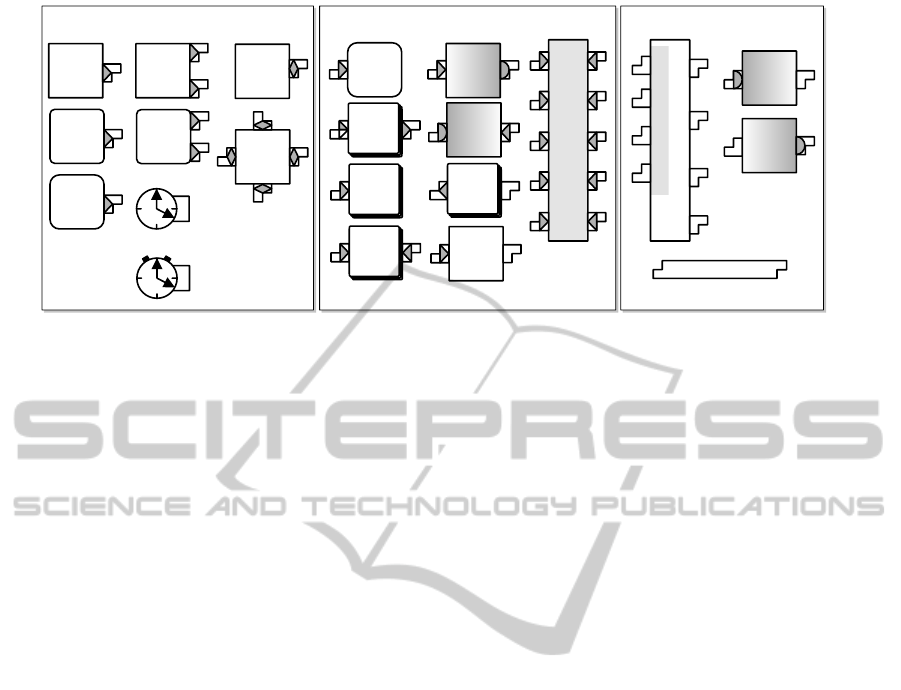
Bus Master and Timing Elements
T
Clock
ISP
Princeton
Memory
Hub
Controller
Direct
Memory
Access
ASIP
Princeton
ASP
ISP
Harvard
P
D
ASIP
Harvard
P
D
T
Timer
Bus Slaves
D/A
Converter
A/D
Converter
Bus
(e.g.
CAN)
SPI
ASP
Memory
Memory
(Dual Port)
Cache
CAM
Passive Bus Components
A/D
Converter
8 Bit
D/A
Converter
Arbiter
Bus
Figure 3: Symbols of components.
is possible to describe complex architectures easily.
Such a model is needed because a complex binding
relationship as proposed by MARTE is very hard to
use if an automatic design space exploration has to
be designed and implemented because there exist a
lot of dependency rules between the different views.
A comparable approach is presented in (Liehr et al.,
2008).
In UML, MARTE, or SysML it is only possible
to describe the application or platform view. Bind-
ing and mapping is only supported in a graph based
approach like in (Teich et al., 1997). Memory is not
considered in it. The whole system view is also miss-
ing in all cases. This gap is closed in this paper by
the newly introduced system view and the concept of
platform domains.
4 PLATFORM LANGUAGE
The platform view enables hierarchical design as well
as refinement processes and is divided into two differ-
ent views of a platform. All views describe the same
platform but with different intentions.
4.1 Module and Component Level
The platform view (see Figure 1) starts with modules
to support a hierarchical design methodology. Mod-
ules are for example devices, cards or chips. The
modules can consist of several modules or compo-
nents. Components are the basic functional hard-
ware elements. Therefore modules and components
are elements of a hardware view of addressable ob-
jects. We distinguish between different types of com-
ponents (see Figure 3).
4.1.1 Bus Control Interfaces
Components contain bus control interfaces that are
connection points with a technology type and a bus
control interface contract. The bus control interface
contract is something like the interface type in object
oriented languages. At this level of detail we distin-
guish between the following bus control interfaces:
Active, Passive, Analog and Timing. Only bus control
interfaces with compatible types could be connected
to each other. The interfaces and their symbols are
shown in Figure 3.
The bus control interface could be an active bus
control interface what implies that the component
contains the controller needed for connecting to the
appropriate communication system like a bus. Ac-
tive bus control interfaces are symbolized by a tri-
angle inside the bus control interface symbol. Pas-
sive bus control interfaces will not contain any con-
troller and are therefore only seen as a wiring connec-
tion point. The interface symbol contains no trian-
gle. Analog interfaces are specified to connect analog
building blocks (see section 6). They are symbolized
by a semicircle inside the interface symbol. Finally
Timing interfaces connect timing elements with time
users that could be almost all other components. The
interface symbol differs from the other symbols and it
contains a “T” indicating the timing interface.
4.1.2 Components
Model elements that can act as a bus master are called
bus master components. They are equipped with ac-
tive interfaces with a triangle pointing away from the
component. This indicates the component can com-
mand the bus. Another possibility is a diamond sym-
bol indicating the component can also be commanded
by other components. Examples of bus masters are
processing elements like instruction set processors
SIMULTECH2013-3rdInternationalConferenceonSimulationandModelingMethodologies,Technologiesand
Applications
254
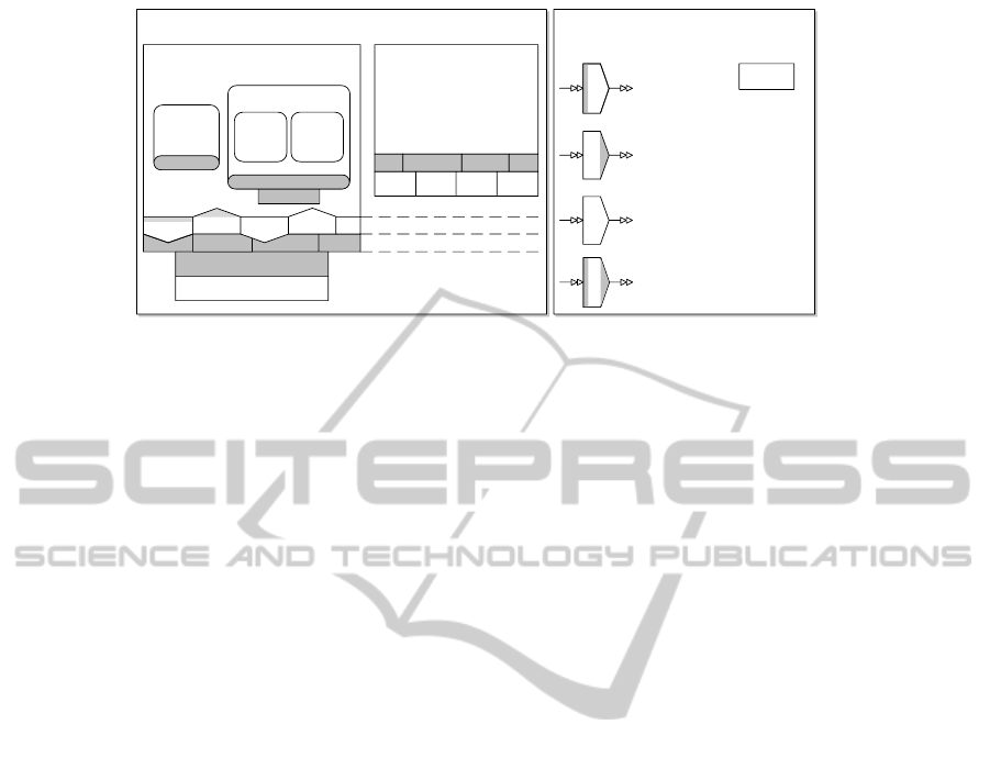
Services, service access points
and their attributes
mem
mem
memmem
blocking write
non blocking read
blocking write
non blocking read
mem
blocking write
blocking read
non blocking write
non blocking read
memory binding
memory binding
memory binding
memory binding
Direct memory
access (pointer)
Domains
Resource domain containing
e.g. service domains
Allocation of resources
Memory Layout
CAN AD ISPMEM
Layout
Service domain, e.g. operating system
with process and thread binding
Scheduling service layer
Processing resource binding
Process
Scheduling
Thread
Process
Thread
Memory
Memory
write
read
read
Memory
write
Device driver and service layer
Memory layout layer
Figure 4: Symbols of domain level elements.
(ISP) or application specific instruction set processors
(ASIP), direct memory access controllers and mem-
ory controller hubs also known as bus bridges. These
components and their symbols can be found in Fig-
ure 3 in the area of Bus Master Components.
Bus slave components are components that will
be commanded by bus masters. They are equipped
with active interfaces containing a triangle pointing to
the component. Bus slave components are for exam-
ple memories and caches including their controllers
(symbolized by a stack of memory cells) or buses
with active controllers as a CAN bus for example.
The memory addressing scheme – virtual or physi-
cal - could be modeled as an attribute of a component
like a cache or instruction set processor. This implies
that a memory management unit or a memory protec-
tion unit is not modeled as separate component but
as this attribute. The interface of such a virtual ad-
dressing is indicated by a double bar triangle. These
components can be found in Figure 3 in the area of
Bus Slave Components.
Passive bus components will not contain an active
controller. They are connected by passive bus con-
trol interfaces. For example buses without controllers
are passive bus components. Another example is an
AD/DA converter that should be connected to a pas-
sive bus control interface (only wires).
Timing elements are components that model
timers and clocks. They can be connected to all other
elements and will be symbolized by a clock with a
timing interface.
4.2 Domain Level
The modules and components can then be refined by
domains. In our approach we distinguish between
two types of domains: Resource domains describing
the resources of the platform and service domains de-
scribing the offered services with their access points
that are mapped to application elements in the system
view. Symbols for domains and their containing el-
ements are shown in Figure 4). In the domain level
no direct connections between model elements with
arrows or lines are used, elements are connected by
their names and position.
The idea is to define an abstraction layer which
covers all aspects of a platform as seen by the appli-
cation. In embedded or cyber-physical system design
this could be a view on operating system services as
device drivers or schedulers as well as the memory
layout. The new layer defined in this section allows
to model the platform aspects in an abstract way. It
allows the designer to concentrate on the architecture
and it hides the aspects of implementation details. To
introduce modeling components and graphic symbols
for this part is new. In further work software engi-
neers model the platform in a software way to inter-
pret the services as software functions like applica-
tion functions and hardware engineers are not inter-
ested to consider scheduling or memory architectures
as seen by software. Therefore to describe the archi-
tecture of a hardware/software system the aspects of
the platform must be considered as an architecture of
hardware as seen by the application (and not only by
software).
4.2.1 Resource Domains and Resources
Resource domains can contain other resource do-
mains, service domains and resources that are the sub-
stitution of hardware components. They also contain
the memory layout of their resources. A resource
domain contains all relevant resources of the consid-
ered system or subsystem. Resource domains inside
of other resource domains are a logical group of the
system resources. This enables hierarchical composi-
tion of resource domains and encapsulation of subsys-
tems. For communication between these subsystems,
a resource in the superior resource domains is needed.
AbstractModelingofembeddedSystemsHardware
255
FFT
t
s
FFT
t
s
IFFT
t
s
Main
Controller
Multiplication
*
NIOS
Aplication Specific Scheduling
FFT
«analog» Tranceiver
Low Pass Filter
Amplifier
Transducer
M
E
Voltage
Source
Level
Converter
Voltage
Multiplier
U
U
TX
RX
Sound
A/D
A
D
D/A
A
D
DM1
PRIO
MEM
($07FFF - $FFFF, 24 K)
DM2
($03FFF - $07FF, 16 K)
DM1
($0000 - $03FF, 16 K)
NIOS
FFT
CANPWM
DM2
wmem
CAN
CAN
DM2
DM1
DM1
wmem
CANCAN
DM1
DM2
DM2
MEM
Envelope Filter
MEM
MEM
wmem
Threshold
Filter
Application Specific Register File
REG3
REG REG2
Sample
Time
1 MHz
DM2
Signal
Generator
PWM
Pulse Response
Time
4 Hz
Timer
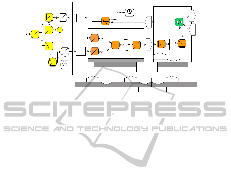
Figure 5: The system level domain architecture of the sonar system.
The root node of domains is in every case a resource
domain that is a visualization of the system border.
As mentioned above, resource domains contain
only relevant resources. That are resources used
by the services of the containing service domains.
It is not intended that all hardware components are
mapped to resources e.g. an address bus is a com-
ponent element that is needed for the correct work of
the system but it is not used explicitly (but implicit)
by services and not modeled as a resource.
Resources are the substitution of hardware com-
ponents in the domain level. A domain contains all
relevant resources of the considered system or sub-
system modeled by the domain. As mentioned above,
domains contain only relevant resources. That are re-
sources that will be used by services.
4.2.2 Service Domains and Services
The concept of service domains establishes a service-
oriented view to platforms. They are an abstraction
for operating systems, frameworks, processes and
threads. Service domains itself can contain service
domains. At the lowest level a service domain is a
process or thread. They contain services, their access
points and the memory layout of these services.
Services are a concept to provide and manage
computing resources. They are bound to underlying
services or directly to resources. Services are divided
into the following types: processing, communication,
storage and timing. This categorization can be ex-
tended easily. Services are used by the application
through service access points. They model the usage
of services and are therefore a kind of configuration
of the services depending on the current application.
4.2.3 Memory Layout
The memory layout consisting of memory partitions
is available in every kind of domain. It describes the
address space and size available for that domain. Re-
sources and services will be assigned to memory par-
titions. A memory layout of a process describes the
private memory of that process. This private memory
is only virtual as it is not directly bound to a memory
resource but to a memory service of the containing
operating system.
5 CASE STUDY
In this section, a design example is considered that is
derived from (Slomka et al., 2011). The sonar system
is part of a larger project, an autonomous underwater
vehicle (AUV). The major task of the sonar system is
to detect objects in the water that will be used for nav-
igation and maneuvering of the robot. The sonar sys-
tem sends acoustic waves into the water and, if there
is any object, receives the acoustic reverberation of
that object. It consists of an electromechanical part
to generate acoustic signals, an analog electronic part
to drive the electromechanical sound generator and to
receive the reverberation, and a digital electronic part
with hard- and software for signal processing and tar-
get detection.
In this case study we will focus on the design of
the platform fulfilling the requirements of the applica-
tion as stated above. The application design, system
design and requirements analysis are shown in detail
in (Slomka et al., 2011).
SIMULTECH2013-3rdInternationalConferenceonSimulationandModelingMethodologies,Technologiesand
Applications
256
Direct
Memory
Access
MEM
DM2
A/D
Converter
D/A
Converter
Arbiter
Bus
FFT
DM1
NIOS
P
D
Direct
Memory
Access
BusBus
T
PWM
T
4 Hz
Timer
CAN
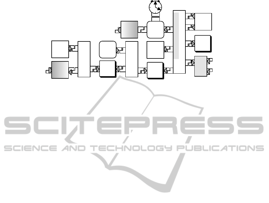
Figure 6: Platform level component architecture of the sonar system.
5.1 System Mapping and Domains
Three service domains are manually chosen for sig-
nal generation, fast fourier transformation (FFT) and
main controller (see Figure 5). This is one possible
kind the domain architecture chosen here for simplic-
ity.
The next step is specifying the services to real-
ize the communication that is modeled by messages
or binary signals between computational tasks. As
displayed in Figure 5 the communication services are
placed between the communication links of the ap-
plication. The points were the communication links
are connected to the service are the service access
points. This is the way to visualize the binding of
communication to the platform. Tasks that transform
from digital to analog domain or vice versa are known
as transformers and contain a digital and an analog
port. The digital port will be mapped to a communi-
cation service access point. Next, the tasks itself are
all mapped to a processing service access point to en-
able scheduling of the tasks. Application tasks that
use timing information are called timing tasks. They
will be mapped to a timing access point. They pro-
vide the timing information via ports and are mapped
to communication service access points.
It is already needed to create at least one resource
domain containing all the hardware resources of the
entire system. The result is shown in Figure 5. The
domain implementing the fast fourier transformation
(FFT) is not considered any more in the system level
but specified in the hardware synthesis. Therefore the
communication services are displayed with dashed
lines and the memory layout and scheduling is defined
as “application specific”.
5.2 Generation of Components
After specifying the domain architecture components
and modules are generated or selected implementing
that domains. This decision is a task of the system
architect. Both ways are supported by the approached
methodology and both ways could be mixed. In our
current case study we decided to select components
and modules manually from a list of available items.
Processing resources are transformed to bus mas-
ters like ISPs, ASIPs or ASPs (see Figure 3) depend-
ing on the scheduling services and attributes. Memory
resources will be transformed to memory elements.
If caching is used by the memory layout, cache ele-
ments are added. Timing resources are transformed
to timers and clocks. Communication resources are
transformed into the active or passive communication
infrastructure. Resources of different domains can
communicate with each other by coupling elements.
Examples are memory hub controllers, buses or dual
ported memories. In our case study the dual ported
memory DM2 (see Figure 6) is used as a coupling el-
ement.
The automatic generation of components and
modules will be done using formal transformation
rules. They describe the transformation of elements
of the resource domains and corresponding service
domains to elements of the component level. For-
mal transformations are part of our future work (see
Sect. 6).
6 CONCLUSIONS
The paper introduces a new abstraction level in sys-
tem design. The goal is to bridge the gap between
structure diagrams as used by hardware engineers and
class and module based diagrams as used by software
engineers. It includes graphical modeling of applica-
tion and platform which are mapped together at the
newly introduced system view in an intuitive graph-
ical way. The fact is, that methods like UML are
AbstractModelingofembeddedSystemsHardware
257

mainly used to model applications and therefore ab-
stract from architectural details as memory layout or
scheduling. But both these parts are essential for the
design of cyber-physical or in general way embedded
systems. The results presented in this paper are a new
way to describe architectures of embedded platforms
considering aspects of the design of the hardware plat-
form. Therefore it allows the exploration of different
platform implementations in early design phases of a
project.
Future work will cover the meta modeling to inte-
grate this new technique to UML as well as formal
transformations to support system optimization and
design space exploration. To validate our approach
an implementation of the design methodology and de-
sign flow in combination with usability investigations
are some more tasks to do. This will include a com-
parison with other modeling methodologies.
REFERENCES
AUTOSAR development cooperation (2013). AUTomotive
Open System ARchitecture. http://www.autosar.org/.
Boulet, P., Marquet, P., Piel,
´
E., and Taillard, J. (2007).
Repetitive allocation modeling with marte. In Forum
on specification and design languages (FDL07).
Carloni, L., De Bernardinis, F., Pinello, C., Sangiovanni-
Vincentelli, A., and Sgroi, M. (2005). Platform-Based
Design for Embedded Systems. In The Embedded Sys-
tems Handbook. R. Zurawski (Ed.).
Gajski, D. (1992). High-Level Synthesis. Kluwer.
Lee, E. (2008). Cyber physical systems: Design challenges.
In 11th IEEE Symposium on Object Oriented Real-
Time Distributed Computing (ISORC).
Liehr, A., Rolfs, H., Buchenrieder, K., and Nageldinger,
U. (2008). Generating marte allocation models from
activity threads. In Forum on Specification, Verifica-
tion and Design Languages (FDL08), pages 215–220.
IEEE.
Marwedel, P. (2011). Embedded Systems Design - Embed-
ded Systems Foundations of Cyber-Physical Systems.
Springer, 2nd edition.
Object Management Group (OMG) (2010). OMG Systems
Modeling Language, version 1.2 (OMG SysML).
http://www.sysml.org/specs/.
Object Management Group (OMG) (2011). Modeling
and Analysis of Real Time and Embedded sys-
tems, version 1.1 (MARTE). http://www.omg.org/
spec/MARTE/1.1/.
Object Management Group (OMG) (2013). Unified Mod-
eling Langauge (UML). http://www.uml.org/.
Sangiovanni-Vincentelli, A. and Martin, G. (2001).
Platform-Based Design and Software Design Method-
ology for Embedded Systems. In IEEE Design and
Test of Computers, volume 18, pages 23–33.
Slomka, F., Kollmann, S., Moser, S., and Kempf, K. (2011).
A multidisciplinary design methodology for cyber-
physical systems. In 11th IEEE Symposium on Object
Oriented Real-Time Distributed Computing (ISORC).
Sommerville, I. (2001). Software Engineering. Pearson
Studium.
Teich, J., Blickle, T., and Thiele, L. (1997). An evolutionary
approach to system-level synthesis. In CODES, pages
167–172.
SIMULTECH2013-3rdInternationalConferenceonSimulationandModelingMethodologies,Technologiesand
Applications
258
