
Low Latency of Re-authentication during Handover
Re-authentication using a Signed Token in Heterogeneous Wireless
Access Networks
Hassane Aissaoui
1
, Pascal Urien
1
and Guy Pujolle
2
1
Network and Computer Science Department, TELECOM-ParisTech : LTCI CNRS Laboratory, rue Barrault, Paris, France
2
LIP6-University Pierre and Marie Curie Paris VI: CNRS Laboratory, 4 Place Jussieu, Paris, France
Keywords: Wirless, Roaming, Handover, Digital Signature, Signed Token, Trusted Infrastructure, (Re)-authentication,
(Re)-association, Mobility Anytime Anywhere, Ubiquitous Access, Low Latency, Real-time Applications,
AAA Framework, IEEE802.1x/EAP Protocol.
Abstract: Wireless networks provide several advantages over wired networks. They offer: a satisfactory bandwidth,
mobility, easy deployment in difficult areas, long-term savings and the speed more and more higher.
However, they also have some disadvantages in regard to security, performances during re-authentication,
execution of real-time applications and interference from other electromagnetic sources (Bluetooth,
microwave, etc.).
The existing solutions to reduce delays of Handover intercellular are specific solutions to a particular
network or manufacturer of this technology.
The main objective of this paper is to propose novel mechanisms based on digital signatures to obtain low
latency re-authentication during Handover in Wireless Access Networks. Our infrastructure will be based on
trusted relationship between the heterogeneous access points and the authentication servers, in order to
allow the mobility anytime anywhere to any user, and the ubiquitous access to the Future Internet, while
ensuring the right level of security to both the end users as well to the wireless networks.
In this context, the main issues are to resolve the seamless Handover and the re-authentication during
mobility of station. By using a signed token in our trusted infrastructure, we achieve a unique authentication
and a fast re-authentication. Therefore, the requests to the authentication server are considerably limited.
1 INTRODUCTION
Unlike the Global System for Mobile
Communications (GSM), the concepts of "Roaming
and Handover" represent different actions.
In general, the process of handover is natively
implemented in Mobile Station (MS), Base Station
Controller (BSC) and Mobile Switching Center
(MSC). The handover process in GSM involves four
steps: the measurement, the request, the decision and
the execution of handover. The request of the
handover is generated by the BSC, and the decision
is provided by the MSC. the other steps can be
maintained by the BSC.
In wireless technologies, the Handover is a
process that represents a mobility of the mobile node
(MN) to another target Point of Attachment (PoA),
which offers a higher radio link quality.
The Handover is a fundamental mechanism in
the inter-cellular communication; involving a set of
operations that allows the mobile station to change
the PoA without losing the connectivity and the
session. These operations generate several steps and
every single step causes delays and has an impact on
the real-time applications such as Voice over IP
(VoIP).
The rest of this paper is structured as follows: In
(Section 2), we present an overview of the
constraints and the causes of the inter-cellular delays
and the impact of security on the Handover. In
(Section 3), we examine proprietary solutions and
improvements to the Wireless Local Area Networks
(WLAN) or IEEE 802.11 Standards (WLAN 1997).
We will analyze, (Section 4), the WLAN
Standards and Authentication, Authorization and
Accounting Framework (AAA, 2000) which is based
on Extensible Authentication Protocol (EAP 2004).
248
Aissaoui H., Urien P. and Pujolle G..
Low Latency of Re-authentication during Handover - Re-authentication using a Signed Token in Heterogeneous Wireless Access Networks.
DOI: 10.5220/0004608602480254
In Proceedings of the 10th International Conference on Signal Processing and Multimedia Applications and 10th International Conference on Wireless
Information Networks and Systems (WINSYS-2013), pages 248-254
ISBN: 978-989-8565-74-7
Copyright
c
2013 SCITEPRESS (Science and Technology Publications, Lda.)

In (Section 5), we illustrate the advantages and
properties of digital signature that allow privacy and
authenticity of a message, freshness against replay
attacks / anti-replay, non-repudiation and anonymity
(ISO 7498-2:1989). In (Section 6), we present our
contribution which involves the use of asymmetric
cryptography to sign tokens after client
authentication, how this token save the context of a
user session and how the stations perform a fast re-
authentication during a Handover with this token?
Finally, we present in (Section 7), a conclusion
and perspectives for future work.
2 INTERCELLULAR HANDOVER
PROBLEMS
2.1 Delays Due to Technology IEEE
802.1X Protocol
Delays due to Handover have been for a long time a
recognized problem in wireless networks.
Certain experimental studies (Mishra et al.,
2003) and (Velayos and Karlsson, 2004), attributed
the delay in the IEEE 802.11 networks to the
following phases: scanning, re-initialisation, re-
association and re-authentication, during which a
wireless station discovers neighboring access points.
According to (Zrelli and Shinoda, 2007), the use
of EAP authentication causes significant delays
regarding the re-authentication phase. Indeed, the
EAP is a component of the AAA Framework to
secure and control access to different networks.
In this centralized Framework, the delays due to
the EAP protocol, during re-authentication phase of
a mobile station can become a problem, especially in
the use of real-time applications.
When the mobile station moves to a new AP, it
loses its attributes and continuity of the session, and
must re-authenticate again with the centralized
Framework. This process of the re-authentication
greatly increases latency during the Handover.
2.2 Constraint of Real-time
Applications
VoIP is a real-time application, which imposes itself
as the main application to test the validity of the
performance of Handover in the wireless network.
Indeed, the main constraint of VoIP is the continuity
of the flow so that there is no break in the
conversation (da Conceicão et al., 2006), because
human ear perceives a break of the voice greater
than 50 ms during a VoIP communication.
3 OVERVIEW OF SOLUTIONS
THAT IMPROVE HANDOVER
In real-time applications, it is important to reduce
the time of re-authentication and re-association
during the Handover process while supporting
advanced security mechanisms.
Table 1: Effect of roaming on Packet loss (Exact copy
from a Source: Bangolae et al., 2006, p.6)
Authentication
method
Average
Roaming
time (ms)
Average
Packet Loss
%
Maximum
Consecutive
lost datagrams
(Average)
Baseline – Full
802.1x EAP
Authentication
525 1.8 53
Fast Transition
using 802.11r
42 0.2 6
Many enhancements have been made to the
802.11 standard (IEEE 802.11i), but it is not easily
adaptable to the mobility of real-time applications
(Bangolae et al., 2006). Implementing a caching
mechanism in 802.11i has not improved the time
roaming, it is around 350 milliseconds. This time of
switching to a new AP is 7 times higher than the
maximum latency for VoIP (which is about 50 ms).
In (Table 1), it shows the average time roaming
(525 ms) and packet loss (1.8%) using basic
authentication 802.11i, especially when there is a
traffic load of the back-end (eg: Remote
Authentication Dial In User Service) (RADIUS,
2000).
The first solution developed to reduce the latency
in Handover is the Inter Access Point Protocol
(IAPP). Based on IAPP, the Institute of Electrical
and Electronics Engineers (IEEE) in 2003 led to the
drafting of a "Trial-Use Recommended Practice"
which presents the 802.11f (IAPP, 2003). The
deployment of this recommendation has been
virtually no communication. Despite this ratification,
the manufacturers have continued to implement their
methods of Roaming in their wireless networks
technologies. It was abandoned in 2006 for various
reasons, in particular the very slow Handover
latency.
LowLatencyofRe-authenticationduringHandover-Re-authenticationusingaSignedTokeninHeterogeneousWireless
AccessNetworks
249
4 IEEE 802.1X / EAP AND AAA
FRAMEWORK
4.1 IEEE 802.1X
The Port Based Access Control or IEEE 802.1X
protocol is developed by the IEEE based on the
control ports (IEEE 802.1X, 2001). It allows access
to a network after authentication from a wired or
wireless network. The main components of this
mechanism are presented as following:
Supplicant: the system that will be authenticated
(station: STA).
Authentication Server (AS): that manages user
accounts (AAA Framework, RADIUS).
Authenticator: network equipment that plays the
role of mediator between the STA (Access Point,
Switch ...) and AS.
Each AP shares a secret with AS, to enable them to
perform mutual authentication and establish a secure
channel.
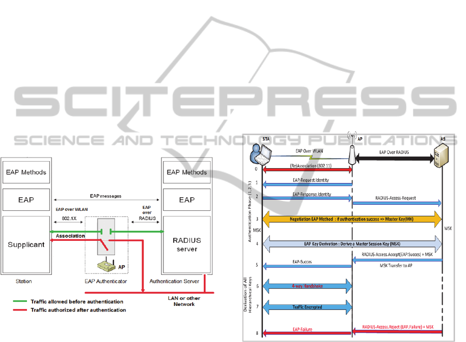
Figure 1: 802.1X architecture of authentication.
The STA also shares a secret with the AS,
usually it is an username and password, as the STA
is not authenticated, 802.1X does not allow it access
to the network, only exchanges related to
authentication processes are relayed to the AS by the
AP. Once the STA is authenticated, the AP permits
the traffic related to this STA “Figure 1”.
4.2 IEEE 802.1I and EAP Protocol
IEEE 802.1X is based on EAP authentication
methods that are specified in the RFC 3748 standard
and respect the requirements of the standard RFC
4017, in order to provide mutual authentication
between a station (STA) and the local network.
There are two kinds of traffic EAP “Figure 1”:
EAP over LAN (EAPoL) or EAP over WLAN
(EAPoW): EAP is transported in these specific
frames between the Supplicant (STA) and
Authenticator (AP).
EAP over RADIUS (EAPoRADIUS) : are the
frames transported between the AP and the
authentication server (AS). The dialogue
between both is a simple "re-encapsulation" of
EAP packets without modifying the contents of
the package by the AP.
EAP is a transport protocol for authentication. It
defines mechanisms for exchanging authentication
between devices. In order to get the access to a
wireless network infrastructure, the STA must be
authenticated.
As shown in phase 0, "Figure 2": the first step is,
of course, the association 802.11, of the STA to AP,
which must be done previously at 802.1X
authentication phase.
Figure 2: EAP Exchanges.
The authentication phase is then initiated via
traffic (EAPoW):
Phase 1: (EAP-Request.Identity) sending a
request from the AP to the STA.
Phase 2: (EAP-Response.Identity) is STA
response to the request, and attaching a first
identifier (EAP-ID). This response is
retransmitted to the RADIUS server via (EAP
Over Radius) in the request (Access.Request).
Phase 3: From this time, the second stage begins
exchanges that depend on the chosen
authentication method (EAP-TLS, EAP-TTLS,
WINSYS2013-InternationalConferenceonWirelessInformationNetworksandSystems
250

EAP-MD5, LEAP, etc.). Therefore EAP
messages (requests and responses) are exchanged
between the RADIUS server and the STA. If the
STA is authenticated, the AS and the STA
negotiate a Master Key (MK). This MK is only
valid for this session between the STA and the
AS. The access point plays only a passive relay
at the moment.
Phase 4: After successful authentication, the
STA and the AS derive from the MK a secret key
called "Master Session Key" (MSK), during one
of the last messages sent by the AS. This key is
known only by the client and the server. The
MSK can be derived only by the client and the
AS.
Phase 5: At the end of these exchanges AS
indicates to the AP the success of this procedure
with EAP-Success message. Then, the AS
transfers the MSK to the AP in the
Access.Accept packet in the attribute "Microsoft
Vendor-specific RADIUS Attributes" (RFC
2548, 1999) and (RFC 3078, 2001). This
Attribute contains (MS-MPPE-RECV-KEY), a
session key for use by the Microsoft Point-to-
Point Encryption Protocol (MPPE). This key is
intended for encrypting packets received by the
Authenticator from the remote STA. It is
included in RADIUS-Access-Accept packets.
From this moment, the server has no interaction
and the exchanges continue between AP and
STA. The AP takes decisions on access control
LAN instead of the server.
Phase 6: The MSK is used as the symmetric key,
which is valid only for this session between the
STA and the AP. This symmetric key will be
derived in three keys between the STA and the
AP, using the protocol "4-way handshake".
Especially, the Group Transcient Key (GTK)
shared by all stations connected to the same AP.
It is only used to secure the Multicast and
Broadcast in the Basic Service Set (BSS). It is
renewed every time a workstation disassociates
from the AP.
Phase 7: All network traffic between the AP and
the STA is encrypted.
Phase 8: When the STA is not authenticated, the
AS indicates to the AP the failure of this
procedure with EAP-Failure message.
5 DIGITAL SIGNATURES
One of the main advantages of asymmetric
cryptography is that it offers the possibility of using
digital signatures. According to ISO 7498-2, these
signatures are used to verify the following
properties: the authenticity of the author of an
electronic message, but also to ensure its integrity
and non repudiation.
The digital signature (Menezes et al., 2001,
Chapter 11) proves to the recipient of a message that
it has been signed by the author, because it is
authentic and difficult to imitate. It is not reusable,
and is an integral part of the document.
The Asymmetric Cryptography consists of two
asymmetric keys (public / private). The keys are
mathematically related. An encryption key and a
decryption key are different; one key cannot be
calculated from the other.
In general, one of the keys is public and known
by everyone. This key will be used by any person to
encrypt a message. The original message is
extremely difficult to find as it can only be
decrypted by the person who possesses the second
secret key called the private key.
Figure 3: Encryption and decryption with an asymmetric
key.
The operation of asymmetric encryption is
simple “Figure 3”: Bob encrypts the text using the
public key of Alice. Alice can decrypt the text with
the associated key.
So it is possible to encrypt a message securely
with the public key, and only the person with the
private key can decrypt it.
Figure 4: Digital signature.
The digital signature is the opposite principle of
public key encryption “Figure 4”.
Alice encrypts a message with her private key.
The result obtained can be decrypted by anyone with
the associated public key. This confirms that Alice
has signed the content of this message. She cannot
LowLatencyofRe-authenticationduringHandover-Re-authenticationusingaSignedTokeninHeterogeneousWireless
AccessNetworks
251

repudiate it and can be verified by a third party.
When the document is voluminous, it must be
first hashed into just few lines. This process is called
a message digest. Then, the message digest must be
encrypted using the private key. The result is the
digital signature. This digital signature is appended
to the document and sent to the recipient.
First, the recipient decrypts the digital signature
(using public key) and obtains the message digest.
Then, the recipient hashes the received document
into a new message digest. If the two message
digests are the same, the recipient knows that the
signed data has not been changed.
6 CONTRIBUTIONS
As mentioned above, in order to obtain an access to
a wireless network infrastructure, the STA must be
authenticated and must share the MSK secret with a
PoA (an AP) “Figure 3”. Therefore, the AS has no
role and exchanges continue between AP and STA.
The AP makes decisions on granting access to the
LAN.
Our approach consists to reuse the MSK, shared
between the STA and the AP, in each re-
authentication to ensure the continuity of the session
of the STA.
6.1 Principle of Virtual ESS (VESS)
At the beginning of wireless network, the protocol
exchanges between STA and AP were much
simpler. The packet number, to establish a
connection, was mainly of four messages. With
secure standards, the number of messages increased
considerably.
Our contribution proposes enhancements to
IEEE 802.11i standard, which allows a station to
switch faster and seamlessly from one AP to another
target. The idea is based on the signed token with an
Asymmetric Cryptography to establish a trusted
infrastructure. This trusted infrastructure can be
considered as a wireless network infrastructure of
the same ISP “Figure 5” and consists of one or more
AS & AP.
In this large infrastructure of distributed access,
we use multiple AS to simplify management and
ensure the scalability of the infrastructure.
Each AS handles APs or a Basic Service Set
(BSS), which are deployed on the private key.
However, the public key is deployed only on APs.
We have restricted the deployment of asymmetric
keys only to AS and APs.
The private key is used to sign the tokens after
each authentication of the STA. The signed token
saves the context of a user session and can contain in
particular: "Time-Stamps" (to limit the token in
time), the message (EAP.Success), and the MSK
shared between the STA and the AP. For other uses,
this token may also contain: STA attributes, user
profile, etc.
Figure 5: Virtual ESS infrastructure.
These APs are interconnected by a Distribution
System (DS), usually is LAN on which the APs are
interconnected. These different BSS interconnected
via a DS in the same LAN are called an ESS
(Extended Service Set). An ESS is identified by an
ESSID.
The V.ESS is an extension of the ESS. It plays
the role of an approval authority. In this trusted
infrastructure, one of the "AS" signs the token with
the private key and the AP decrypts it with the
public key.
In other words, when a STA is authenticated by
AS-1 in BSS-1 “Figure 5”; this AS-1 signs a token
with attributes of the STA, including the MSK
negotiated as seen in (Section 4 “Figure 2” Phase 4),
and this token is sent via AP-1 to the STA.
When the STA moves to AP-3 in BSS-3, it will
present the token. The AP-3 will be able to
authenticate the STA, because it possesses the public
key of VESS infrastructure. It then decrypts the
token to retrieve all attributes, particularly the MSK.
Once the MSK is recovered, it can be reused and
derived by AP-3 and STA as seen in (Section 4
“Figure 2” Phase 6).
Remark 1: We notice that the AS-2 in DS-2 is not
involved in this process of re-authentication because
the re-authentication service has been delegated
partially to the APs. This is to avoid the Back-End
authentication, and to simplify considerably the
number of authentication request between the Back-
WINSYS2013-InternationalConferenceonWirelessInformationNetworksandSystems
252
End and the STA.
6.2 Use Case: (Re)-authentication
Process in VESS
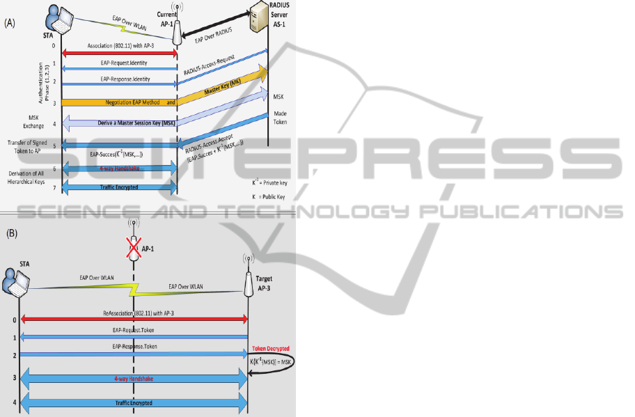
We illustrate in “Figure 6” the authentication
process and, during mobility, the re-authentication
process of the STA in VESS infrastructure.
Figure 6: Virtual ESS: approved infrastructure.
Scenario 1: STA authentication with AP-1
“Figure 6 (A)”
Phase 0: during this phase initialization and
association, STA and AP-1 negotiate the EAP
method with token signed.
Phase 1-2-3-4: authentication of STA and
negotiation of the secret key (MSK). In these phases,
nothing changes.
Phase 5: AS-1 signs the token containing (attributes,
user profile, "Time-stamps", message EAP.Success
and MSK) with the private key, and transmits to the
AP-1 the token signed in Access.Accept:
K
-1
= is private key,
Access.Accept(EAP.Success+MSK+K
-1
{MSK…})
Then the AP-1 forwards the EAP.Success and
signed token packet to the STA:
EAP.Success+K
-1
{MSK…}
Phase 6: the "4-way handshake" protocol, STA and
AP-1 derived from the MSK, a bunch of keys used
only in this session with AP-1.
Remark 2: In this scenario, “Figure 6 (A)”, the
exchanges between the STA, AP-1 and AS-1 are
almost identical as in “Figure 2”. The only
difference consists in signing a token after the
authentication process of the STA. This signed token
ensures continuity of service and the session of the
STA.
Scenario 2: STA re-authentication with AP-3
“Figure 6 (B)”
In this scenario of mobility, the STA transits the AP-
1 to AP-3. Phase 0: during this phase re-initialization
and re-association, the STA and AP-3 negotiate the
EAP method with token signed.
Phase 1-2: STA presents the signed token to the AP-
3. The AP-3 decrypts it, using the public key:
verifies the authenticity of the token and extract the
MSK.
Phase 3: with the "4-way handshake" protocol, AP-3
and STA proceed to the derivation of other keys.
Phase 3: with the "4-way handshake" protocol, AP-3
and STA proceed to the derivation of keys, from the
MSK.
The new derivated keyring is different from that
obtained with AP-1. This keyring will be used only
in this session with AP-3.
Remark 3: In this scenario, the STA did not need to
initiate a re-authentication process with AS-2, but it
was meant only to present a signed token to the AP-
3 to be authenticated. With this delegation of the re-
authentication process to the AP-3, we avoided the
invocation of the AS-2, so we reduced sufficiently
the number of requests of EAP authentication;
therefore, the Handover latency will be also low.
The keys negotiation is done in four passes instantly
and seamless.
6.3 Justification of Our Approach
In comparison with other existing solutions (IEEE
80211f, 802.11r, etc.), our approach is very easy to
implement, can use strong authentication
(asymmetric or symmetric cryptography) and does
not require many modifications of EAP
authentication methods. The implementation of our
EAP methods consists in modifying:
LowLatencyofRe-authenticationduringHandover-Re-authenticationusingaSignedTokeninHeterogeneousWireless
AccessNetworks
253

The beacon at the time of the negotiation of the
Robust Security Network Information Element
(RSN IE) to notify the client 802.1x that wireless
infrastructure supports the negotiation of the
tokens signed.
The requests of (re)-association: the STA 802.11
must notify its choice of security policy by RSN
IE included in these requests.
The Access.Accept method to sign the token and
transfer it to the STA and the AP.
7 CONCLUSIONS AND
PERSPECTIVES
This text describes the impact of security on the
mobility and session continuity. We have identified
the limitations of the EAP protocol in combination
with the AAA Framework. This standard is used in
the access control to different network technologies.
Several stages of the Handover process can be
improved. In this paper, we proposed a fast
Handover scheme; taking into consideration only
delays in re-authentication during a transition in the
same VESS.
To do this, we identified our needs in terms of
security in relation to mobility. Thus we proposed to
implement security components at the APs, to
delegate the re-authentication service to APs in the
VESS infrastructure.
In our scheme, the AAA Framework is ignored
during the process of re-authentication. Therefore,
we use a signed token that ensures trust in the VESS
and manages mobility and continuity of the single
session of STA. This proposition can solve the
problem of intercellular delays (see Section II A).
In the next step, our main focus will be to resolve
all technical barriers, evaluate the pertinence of our
approach to meet the constraints of real-time
applications. Finally, we propose improvements to
the EAP protocol and we implement the new
methods for managing virtual organizations with our
signed tokens.
REFERENCES & STANDARDS
Bangolae, S., Bell, C. & Qi, E., 2006, ‘Performance study
of fast BSS transition using IEEE 802.11r’, IWCMC
'06 Proceedings of the 2006 international conference
on Wireless communications and mobile computing
pp. 737-742, 2006.
Da Conceicão, A. F., Li, J., Florêncioy, D. A., & Kon, F.,
2006, ‘Is IEEE 802.11 ready for VoIP?’, Department
of Computer Science, Institute of Mathematics and
Statistics, University of Sào Paulo, Communication
and Collaboration Systems, Microsoft Research.
Menezes, A. J., Van Oorschot, P. C., &Vanstone, S. A.,
2001, ‘Handbook of Applied Cryptography’, Chapter
11, CRC Press, Fifth Printing August 2001, freely
available at <http://cacr.uwaterloo.ca/hac/>.
Mishra, A., Shin, M. & Arbaugh, W., 2003, ‘An empirical
analysis of the IEEE 802.11 mac layer handoff
process’ SIGCOMM Comput. Commun. Rev., vol. 33,
no. 2, pp. 93–102, 2003.
Velayos, H., & Karlsson, G., 2004, ‘Techniques to reduce
the IEEE 802.11b handoff time’ Tech. Rep., 20-24
June 2004.
Zrelli, S. & Shinoda, Y., 2007, ‘Experimental evaluation
of EAP performance in roaming scenarios’, AINTEC
'07 Proceedings of the 3rd Asian conference on
Internet Engineering: Sustainable Internet, pp. 86-98,
2007.
AAA Authorization Framework, 2000, IETF RFC 2904,
August 2000, <http://tools.ietf.org/html/rfc2904>.
EAP, 2004, ‘Extensible Authentication Protocol’, IETF
RFC 3748, <http://tools.ietf.org/html/rfc3748>, Jun.
2004.
IAPP, 2003, IEEE std 802.11F-2003, ‘IEEE Trial-Use
Recommended Practice for Multi Vendor Access Point
Interoperability Via an Inter Access Point Protocol
(IAPP) Across Distribution Systems Supporting IEEE
802.11 Operation’.
IEEE 802.1X, 2001, IEEE Std 802.1X, ‘Standards for
Local and Metropolitan Area Networks: Port Based
Access Control’, June 14, 2001.
ISO 7498-2, 1989, ‘Information processing systems --
Open Systems Interconnection--Basic Reference
Model’ Part 2: Security Architecture.
RADIUS, 2000, ‘Remote Authentication Dial In User
Service’, IETF Std RADIUS RFC 2865, June 2000,
<http://tools.ietf.org/html/rfc2865>.
RFC 2548, 1999, IETF RFC 2548, March 1999,
‘Microsoft Vendor-Specific RADIUS Attributes’,
<https://tools.ietf.org/html/rfc2548>.
RFC 3078, 2001, IETF RFC 3078, March 2001,
‘Microsoft Point-To-Point Encryption (MPPE)
Protocol’, <http://www.ietf.org/rfc/rfc3078.txt>.
WLAN, 1997, IEEE std 802.11, ‘WIRELESS LOCAL
AREA NETWORKS’, The Working Group for
WLAN Standards, <http://www.ieee802.org/11/>.
WINSYS2013-InternationalConferenceonWirelessInformationNetworksandSystems
254
