
Semi-automated Ontology Population from Building Construction
Drawings
Polina H
¨
afner, Victor H
¨
afner, Hendro Wicaksono and Jivka Ovtcharova
Institute of Information Management in Engineering, Karlsruhe Institute of Technology, Zirkel 2, Karlsruhe, Germany
Keywords:
Ontology Population, CAD Construction Drawings, Pattern Recognition, Intelligent Building.
Abstract:
Ontologies have been applied as knowledge representation in different domains, including intelligent building
management. One of the challenges in using ontologies is the population with building specific information,
such as the building elements and the energy consuming devices. The population usually has to be done man-
ually by analysis and interpreting the building drawings, thus it requires extensive work. This is due to the
lack of semantic information in the existing building construction drawings, which only contain geometrical
information. However, it is possible to understand the semantics of the drawings, if the knowledge in interpret-
ing the semantics of the symbols, shapes and other geometric information is present. This paper introduces
a tool to extract the semantic information from CAD drawings and populate the ontology using the extracted
semantic information in a semi-automatic way. The drawing primitives from CAD files are used to perform
the pattern matching and classification algorithms to extract the semantic information. The resulting semantic
information is then mapped to the corresponding ontology classes of a T-Box ontology. Finally individuals
of the corresponding classes are created to populate the ontology and their geometric properties like world
coordinate position and bounding box are set.
1 INTRODUCTION
Buildings are becoming more intelligent. There are
various reasons for this new trend, like energy effi-
ciency, comfort, and rising complexity of multime-
dia devices and intelligent furnitures. Another view
on this is the web of objects (Atzori et al., 2010).
Whereas the web of objects describes an object ori-
ented web of intelligent agents, this work focuses on
the central intelligence of the building. The core com-
ponent of an artificial intelligence is a knowledge base
containing semantic description of the domain and al-
lowing the interaction with the intelligent agents. An
ontology is a common representation to describe the
semantics. It contains the information and concepts
needed for the intelligent building management.
The need for more semantic information has also
been addressed in the development of the Building In-
formation Model (BIM) (Howard and Bj
¨
ork, 2008)
and the introduction of BIM standards like IFC and
gbXML. The way to create the CAD content goes
through a paradigm shift from drawing to configuring
and this facilitates the collection of the semantic in-
formation. The reason one can not take advantage of
those new features now is that they will take effect at
least in the next several years because of their low use
(Laakso and Kiviniemi, 2012). Until then the present
data of recent buildings mostly consist of construction
drawings based on 2D geometric primitives.
Our work addresses the extraction of semantic in-
formations from 2D drawings with the goal to cre-
ate an ontology represented knowledge base for in-
telligent buildings. First one needs to define differ-
ent classes and relation definitions for building man-
agement domains, such as the classes representing
elements like room, door, window and the relations
like hasDoor, hasWindow, etc. This will result in a
T-Box ontology, which can be used as the common
structure and taxonomy for the building information
model. Then, one needs to populate the ontology with
the building specific instances like the list of rooms
with their position and dimensions, the positions of
doors and windows, and the building automation sys-
tems with all the sensors and actuators. The popula-
tion usually has to be done manually, which requires
extensive work. The building plans are usually drawn
in CAD as collections of primitives representing cer-
tain symbols. It needs pre-knowledge in order to in-
terpret the semantic of the drawings and populate the
corresponding ontology.
379
Häfner P., Häfner V., Wicaksono H. and Ovtcharova J..
Semi-automated Ontology Population from Building Construction Drawings.
DOI: 10.5220/0004626303790386
In Proceedings of the International Conference on Knowledge Engineering and Ontology Development (KEOD-2013), pages 379-386
ISBN: 978-989-8565-81-5
Copyright
c
2013 SCITEPRESS (Science and Technology Publications, Lda.)
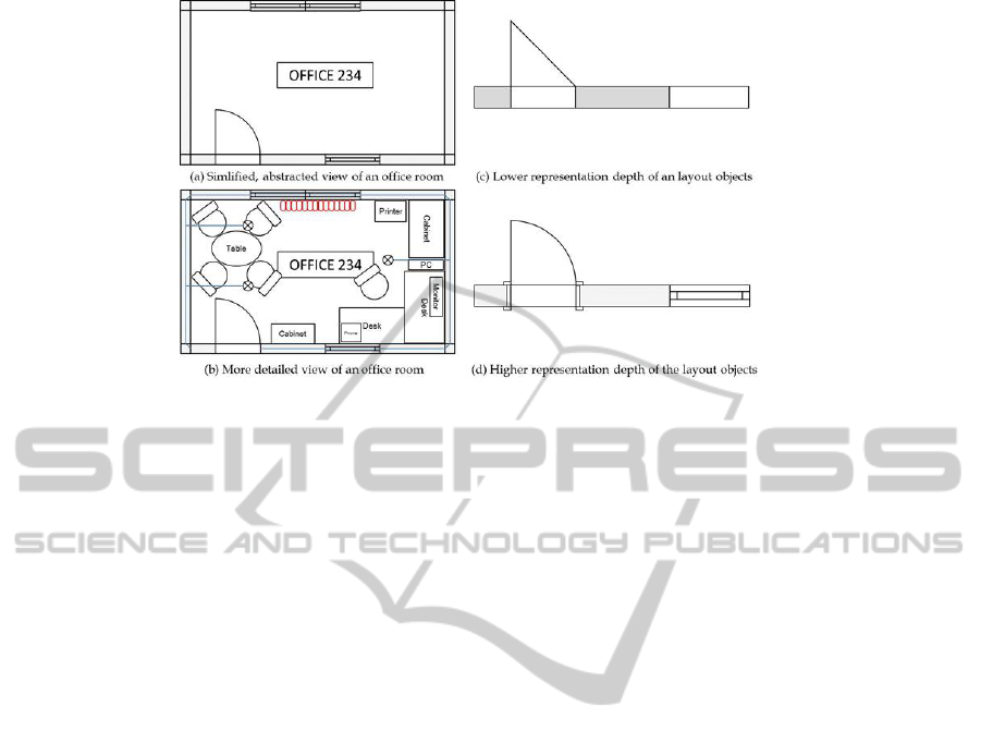
Figure 1: Possible representation of a CAD drawing (Wicaksono et al., 2012).
There are many challenges when extracting se-
mantic geometrical information directly from CAD
drawings and many software products for CAD on the
market used for drawing building layouts. These tools
have versions and variants resulting in many differ-
ences and incompatibilities between them, different
interfaces and import/export file formats. A further
challenge is the varying representation of the building
elements in such a drawing. The quality of the infor-
mation often fully depends on the person who inputs
the data (Vanlande et al., 2008). Figure 1 shows some
examples of different representation possibilities. It
differs in the degree of information density and level
of representation depth. Another problem of the au-
tomated recognition of building elements from CAD
drawings are the different languages used. Each au-
thor labels his drawing using a particular language,
depending on the country. In addition, CAD draw-
ings are often made for different perspectives of the
building so called viewports (top or front projection).
Then a recognition program has to distinguish all per-
spectives. Other kinds of CAD drawings are block
schemes for building domains such as ventilation,
heating, access controls, photovoltaic, electric circuit
etc. To populate the ontology correctly it is impor-
tant to be able to use all layouts of the building (all
floors and all perspectives) in order to avoid informa-
tion loss.
A fully automated pattern matching method to
extract semantic informations from the CAD draw-
ings is not practicable since every drawing differs in
its conventions. The proposed solution focuses on
a semi-automatic approach, enabling the user to se-
lect a building element. The object type is defined
by the user and his information can then be populated
into the ontology. The user selection can be used to
filter all identical objects automatically using pattern
matching algorithms. This is especially useful for re-
curring objects like doors and furniture. Another type
of information are the zones and rooms which can
also be easily populated.
This paper presents the methodology of OntoCAD
and its potential in the field of building ontologies.
This introduction is followed by the state of the art
in ontology population, building layouts, and pattern
matching on primitives. Then the methodology and
implementation of our solution is described. The last
part is dedicated to the conclusion and outlook.
2 STATE OF THE ART
The following section presents the state of the art and
related works in the three topics: ontology population,
building layouts and geometric pattern matching.
2.1 Ontology Population
Ontology population has been a major challenge in
constructing an ontology-based knowledge base. Lit-
erature often describes that a manual construction
of ontology individuals leads to costly and exten-
sive work. Some researchers have proposed methods
to populate ontology semi-automatically in different
domains. However, the population methods depend
strongly on the information sources.
In the semantic web domain, where the informa-
tion sources are semi-structured documents, such as
HTML and XML, the ontology is populated based on
the syntactic and semantic similarity between the on-
tology and the web tables containing terms that are
extracted from web documents. The web documents
are collected by a web crawler. The populated ontol-
KEOD2013-InternationalConferenceonKnowledgeEngineeringandOntologyDevelopment
380

ogy is used for automatic cataloging of IT products
(Song et al., 2009).
Another method for ontology population is in the
risk management domain. The method tries to popu-
late the ontology semi-automatically from fact sheet
documents using combined Natural Language Pro-
cessing (NLP) techniques. It extracts the verbs from
natural language text and matches them to the cor-
responding relations in the T-Box ontology. How-
ever, the human intervention is still needed for control
and validation (Makki et al., 2009). There are some
other works that propose ontology population meth-
ods from unstructured texts based on NLP approaches
(Vargas-Vera et al., 2007), (Maynard et al., 2009). Up
to now, there exists no method to populate ontologies
in the building management domain.
2.2 Building Layouts
CAD design tools, such as AutoCAD, ArchiCAD or
Revit are commonly used for the creation of building
layouts representing two or three dimensional draw-
ing (plans, sections, elevations). Further CAD-based
software is used to plan and model many domains
of a building, such as ventilation, heating, access
controls and photovoltaic (Krahtov et al., 2009). The
number of elements in a sketch and its complexity
may vary (Donath, 2009) (see Figure 1).
Building information modeling (BIM) is the pro-
cess of development and use of computer generated
models to simulate the lifecycle of a facility including
planning, design, construction and operation (Azhar
et al., 2008). The resulting model of BIM is a data-
rich, object-oriented, intelligent and parametric digi-
tal representation of the facility and serves as shared
knowledge resource which helps the decision mak-
ing at each stage of the facility lifecycle (Azhar et al.,
2008). With the BIM model the former 2D construc-
tion drawings are augmented with intelligent contex-
tual semantic, where objects are defined in terms of
building elements and systems such as spaces, walls,
beams and columns (CRC, 2007). To achieve the BIM
concepts, an open standardized data model called IFC
(Industry Foundation Classes) for enabling interop-
erability between BIM software and containing the
semantic information of the facility has been devel-
oped. The reason one can not use the benefits of IFC
for the population of building ontologies is that to-
day after almost 20 years of IFC development (since
1994) we witness the low usage in actual construction
drawings. Laakso assumes that this is caused by the
slow adoption of collaborative model-based construc-
tion processes and industry reluctance to switch over
to new IT tools (Laakso and Kiviniemi, 2012). Even
if IFC becomes more used, there will still be cases
with drawing-like data without semantic information.
2.3 Geometric Pattern Matching
To populate the building ontology in an efficient way,
pattern matching algorithms are used to find all enti-
ties like doors, windows and furniture. There are a lot
of applications where pattern matching plays an im-
portant role. These include pose determination, com-
puter aided design, robot vision and many more. This
work considers a very small subset of pattern match-
ing methods. Spatial pattern matching is the process
of finding a geometric transformation to match two
given images. Only the special case where the im-
age is a 2D vector graphic is called geometric pat-
tern matching. Moreover only exact and total pattern
matching is considered. This is the case for whole
matches with an optimal transformation. This means
that matching patterns are identical. As described by
(Hagedoorn, 2000) there are different methods for ge-
ometric pattern matching, for instance graph match-
ing and geometric hashing. Graph matching means
that the structure of a pattern is described as a graph
and matching is performed between the graphs. Ge-
ometric hashing means that the pattern as a whole is
described by a normalised description. The drawback
of geometric hashing is that it works for known pat-
terns, as a data structure (the hash table) has to be
constructed for the whole data.
This work uses a correspondence method where
patterns are matched by fitting pairs of geometric
primitives. This method combines the geometric
primitives that make up the input pattern. An example
is pairing line segments, where each combination of
two line segments in the patterns must fit to make a
match.
3 SOLUTION
Our methodology uses a semi-automated approach
for the extraction of semantic information from build-
ing CAD drawings using user input at different stages.
The drawings are exported from CAD design software
using the exchange format DXF. OntoCAD imports
and draws the primitives, layers and view-ports. A T-
Box ontology (see Section 3.2) is used as input, which
allows the user to choose building elements from a
building taxonomy. The user can see and use the vec-
tor based primitive representations to add semantic
information. The population process is accelerated
through the OntoCAD user interface and the pattern
Semi-automatedOntologyPopulationfromBuildingConstructionDrawings
381
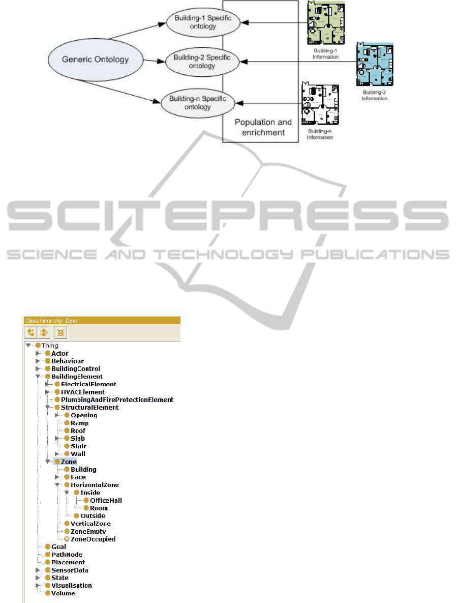
Figure 2: Generic and building specific ontology.
matching algorithms to find the similar objects. The
user has the possibility to directly validate the results
and apply necessary corrections. Each step is con-
tinuously and automatically saved to a building spe-
cific ontology containing A-Box elements. The ad-
vantage of a user-centred method is that the user can
provide meta information about the data like drawing
type (top or side view) or additional semantic infor-
mation like room name or number, supported by an
intuitive graphical user interface. The target user of
our solution can be a facility manager, building owner,
or building management system specialist.
Figure 3: Main classes of the building management ontol-
ogy that will be populated.
3.1 The Ontology Source
In our work, the building management ontology is
represented in OWL (Web Ontology Language), a
W3C specified knowledge representation language
(Smith et al., 2004). Basically there are two types
of ontologies. A generic ontology (T-Box ontology)
represents a common information model for building
energy management, which is then populated and ex-
tended with building specific information resulting in
more building specific ontologies (A-Box ontology).
It is illustrated in Figure 2.
The ontological classes as well as their attributes
and relations representing the resources needed for
the building management are created manually by ex-
perts. The ontology containing these hand-crafted el-
ements is called generic ontology. The generic on-
tology only contains the ontological classes or T-
Box components that describe the knowledge struc-
ture, definitions and terminology. It does not contain
any ontological individuals or A-Box components and
contains no building specific information. Figure 3
depicts the ontology main classes representing the dif-
ferent resources needed for the building management.
The class BuildingElement models the building struc-
tures that are observed, examined and analyzed in en-
ergy management activities. The building elements
are passive entities which have states, but do not have
capabilities to measure or to observe their own states.
The class BuildingElement and its subclasses repre-
sent the fundamentals of the BIM. It is aligned with
the domain layer in IFC2x4.
The aim of the ontology population in our work is
to create individuals for the classes and subclasses of
BuildingElement and to enrich them with geometric
properties. For this, the generic ontology must satisfy
requirements regarding the definition of data and ob-
ject properties. Those properties have to be linked to
each class. This means that a property holds informa-
tion to which classes it belongs.
KEOD2013-InternationalConferenceonKnowledgeEngineeringandOntologyDevelopment
382
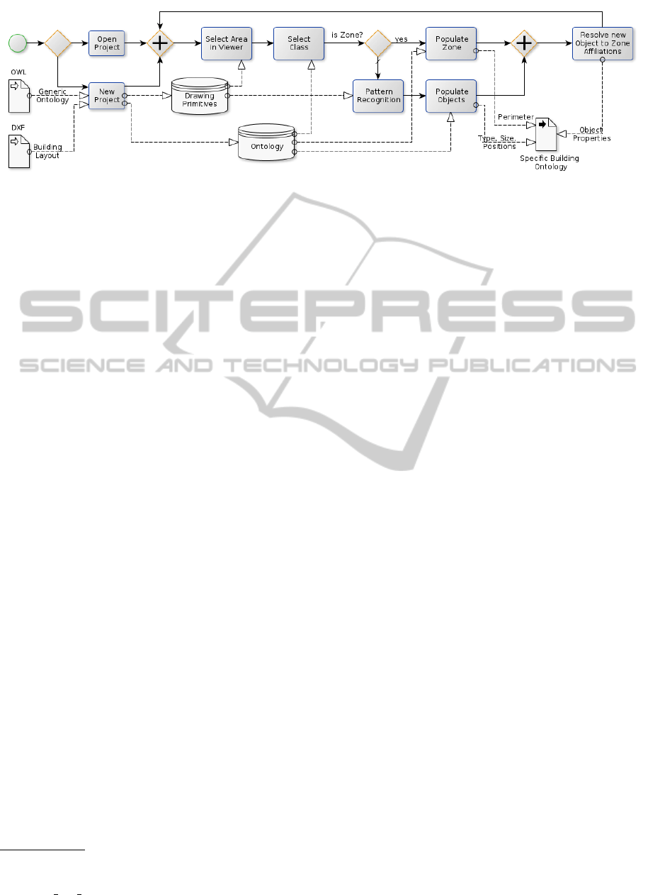
Figure 4: Workflow of OntoCAD.
3.2 OntoCAD
OntoCAD is a tool to populate the generic ontology
with geometric information implementing the pro-
posed methodology. It relies on open libraries like
Python, OpenGL and PyGTK, which make it highly
portable. The architecture is modular and contains
the following five modules: Input interface (for the
CAD drawings and the generic ontology), data model,
graphical user interface (GUI), pattern matching and
population modules. The whole workflow is depicted
on Figure 4.
3.2.1 Input Interfaces
OntoCAD allows the import of 2D Layouts via the
DXF exchange format from Autodesk
1
. DXF export
is nowadays supported in most CAD modelling soft-
ware. OntoCAD imports only the geometric prim-
itives line, arc, circle and ellipse, other geomet-
ric primitives are reduced to supported primitives or
discarded. Other information like metadata is also
discarded. Our DXF parser is partially based on
the FreeCAD implementation, dxfReader.py
2
by Ed
Blake. It is essentially a state machine that constructs
the initial data hierarchy following the open DXF
specifications.
In our work, OWL is used as the language to rep-
resent the ontologies. OntoCAD supports the import
of OWL files with the RDF/XML format that repre-
sents the generic ontology. The classes represent the
taxonomy and are therefore organized in a hierarchi-
cal tree. To populate individuals with OntoCAD, it is
important to know the available classes and the data
properties for each class.
3.2.2 User Interaction
The graphical user interface consists of four main
1
www.autodesk.com
2
free-cad.sourceforge.net/SrcDocu/d7/dd1/
dxfReader 8py source.html
parts (see Figure 5). The toolbar allows to load layout
(.dxf) and ontology (.owl) files and toggle the visu-
alization of the already extracted objects and zones.
The left panel lists all layers contained in the drawing
file, each visualized with a different color. Selecting a
layer from the list will highlight it in the viewer. One
can toggle the visibility of the layer. This will also
affect the performance of the pattern matching algo-
rithm as it will ignore invisible layers. The central
viewer is quite important as the whole methodology
is based on the users experience and visual recogni-
tion of building elements. The viewer uses OpenGL
and a custom shader to render curved primitives like
arcs and circles. The user does not change the primi-
tives except when loading a CAD file, thus the vertex
buffer objects do not need to update during the pop-
ulation process. This makes the viewer very perfor-
mant and guarantees a fluent navigation and interac-
tion. The navigation consists of panning and zooming
into the data and selecting groups of primitives with a
polygon selection tool.
The right side panel allows the user to manipulate
the ontology. The first tab, “Properties”, is a map-
ping of the data properties to a function of OntoCAD.
This is necessary because the data properties are ar-
bitrary strings with no information on how to com-
pute them and cannot be automatically set. OntoCAD
functions calculate for instance geometrical data like
position, area, length, etc. A data property from the
ontology that describes a position could be ‘hasPosi-
tion’, ‘hasLocation’, ‘hasXCoordinate’, etc. Thus it
is important that the user maps those before starting
to populate individuals. This configuration is done
only once, then the user can start populating the ontol-
ogy. Another tab, “Ontology”, visualizes the ontology
class tree to show all the available classes of individu-
als and to help the user to understand the structure of
the OWL file. The “Entity” tab, as seen in Figure 5,
contains a dropdown menu with all available classes,
a button to add individuals and a list of the data prop-
erties of the currently selected class. If a data property
has been mapped to “User input”, then a text entry
Semi-automatedOntologyPopulationfromBuildingConstructionDrawings
383
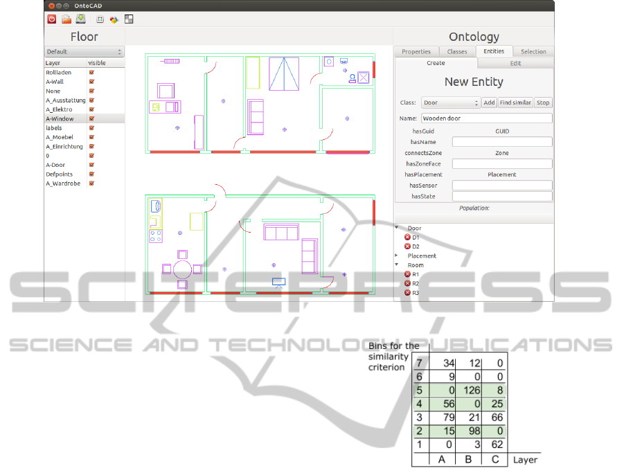
Figure 5: OntoCAD GUI.
will appear next to it, this allows to add additional se-
mantic information, for instance the room type, room
number and room label. When populating two cases
are distinguished:
• Zones or rooms where their perimeter is defined
by the polygon selection tool. There OntoCAD
can provide the selection area, the polygon ver-
tices, or the bounding box of the selection.
• Objects or other small sets of primitives that make
up logical entities. In such a case it is often in-
teresting to search for all duplicates in the draw-
ing to populate all instances at once, for example
lamps or doors. In that case OntoCAD can pro-
vide the bounding boxes, the position, the width
or the length for every instance.
3.2.3 Data Model
The internal data model of OntoCAD consists of the
CAD layout and the ontology. The layout uses five
CAD primitives: points, line segments, circles, el-
lipses and arcs, organized by layers. When loading
a layout, the primitives are copied to a vertex buffer
object for the OpenGL viewer. The ontology consists
of classes in a hierarchical tree, two lists of data prop-
erties and object properties and a list of individuals.
3.2.4 Module for Pattern Matching
Our goal is to get as much semantic information as
possible from the building’s 2D layout, and as auto-
mated as possible. Our approach consists of group-
ing primitives into objects based on a user defined se-
Figure 6: Example of accessing the similar primitives using
the similarity criterion.
lection of primitives. The user has the possibility to
use a polygon selection tool to select all the primi-
tives that belong to a logical building element. The
targeted building elements are recurring ones. This
applies mostly to furniture like tables, chairs, or other
objects that have been inserted multiple times by the
author. Our approach uses primitives to find similar
building elements with the following steps:
• gather a set with primitives similar to the selected
ones
• compute the set of relations between the selected
primitives
• group the similar primitives into objects based on
the above set of relations
The initial step is to take a subset of all the primitives
using criteria that define two primitives as similar. Im-
portant aspects of such a criterion is the rotation and
scale invariance. For our purpose it is important to
have rotation invariance but not scale invariance. This
is based on the assumption that rotated shapes are ro-
tated identical objects but scaled shapes are likely to
KEOD2013-InternationalConferenceonKnowledgeEngineeringandOntologyDevelopment
384

be different objects. Our criteria for lines is the length,
for circles and arcs it is the radius and for ellipses the
minimum and maximum radius. To speed up the pro-
cess a map is kept in every layer where the primitives
are sorted by their similarity criterion. This allows
fast access to the primitives, a subset example is de-
picted on Figure 6. The picture shows how the data is
organized, the numbers represent the amount of prim-
itives in the layer.
To compare patterns of primitives it is important
to define how to describe such a pattern. For this pur-
pose relations between the different types of primi-
tives are introduced. The first and most important re-
lation is the line segment to line segment relation. It
is important to have rotation invariance but no scale
invariance as for the similarity criterion. The line seg-
ment to line segment relation is the set of the four dis-
tances between the line segment endings as illustrated
on Figure 7. This definition of the relation allows
to find matches with transformations corresponding
to euclidean isometries as it preserves the length be-
tween two points.
The last step is to group the primitives into ob-
jects. The constraint is to match the selected set of
primitives. One needs to define what is considered
being a match. First the sets need to have the same
number of primitives, and second all relations have to
exist that are also in the reference set. An example of
matching similar chairs, even rotated, can be seen on
Figure 8.
The algorithm has been highly optimized, also by
using kd-trees and nearest neighbour search. In most
cases the pattern matching performs in under 5 sec-
onds with a building layout having 10
5
line segments.
3.2.5 Output
The result of the population process is the building
specific ontology (A-Box ontology). OntoCAD com-
putes the values for the individuals, their data and ob-
ject properties. This includes geometric information
such as size, area or world position of objects and the
perimeter for zones. Other information are individual
semantic data like type, name, globally unique identi-
fiers (GUIDs) and the building elements affiliation to
zones. All changes are saved continuously and auto-
matically to disk (.owl file). The results can be opened
Figure 7: The line to line relation is defined by the square
values of d1, d2, d3 and d4.
Figure 8: Geometric pattern matching of furniture.
and further edited with other ontology tools (for in-
stance Prot
´
eg
´
e).
4 SUMMARY AND OUTLOOK
Our methodology enables the user to extract and con-
solidate semantic information in a consistent and ef-
ficient manner from 2D building layouts to populate
an ontology. We addressed the challenge of handling
the highly unpredictable data in a generic way by in-
cluding the user to parse small geometric formations
into semantic information. The second challenge re-
lated to process big amounts of data from buildings in
an efficient way. We overcame this by combining the
user input with pattern matching algorithms.
Our implementation, the OntoCAD tool, allows
the user to extract small recurring patterns from a
CAD layout with very little effort and time. Our first
use case is to extract all building elements from a
building layout and use the resulting specific ontology
combined with SWRL rules to run ontology reason-
ing algorithms in order to infer the energy efficiency
states of the building elements.
Our future work will further explore the possibili-
ties and use cases of OntoCAD in different domains.
An interesting extension would be the construction of
a 3D building model from the 2D layout. The primi-
tives forming the walls have to be extruded, moreover
the position of doors, windows and furniture can be
used to augment the building with detailed 3D build-
ing models. We see a high potential of OntoCAD in
the fields of building construction, but also in factory
planning and production management.
ACKNOWLEDGEMENTS
The work introduced in this paper is partially funded
by European Union as part of the project KnoholEM.
Semi-automatedOntologyPopulationfromBuildingConstructionDrawings
385

REFERENCES
Atzori, L., Iera, A., and Morabito, G. (2010). The internet of
things: A survey. Computer Networks, 54(15):2787–
2805.
Azhar, S., Hein, M., and Sketo, B. (2008). Building infor-
mation modeling: Benefits, risks andchallenges. Pro-
ceedings of the 44th ASC National Conference.
CRC (2007). Adopting BIM for facilities management :
Solutions for managing the sydney opera house. ISBN
: 978-0-9775282-2-6 Industry Publication.
Donath, D. (2009). Bauaufnahme und Planung im Bestand :
Grundlagen — Verfahren — Darstellung — Beispiele.
Vieweg+Teubner.
Hagedoorn, M. (2000). Pattern Matching Using Similarity
Measures. PhD thesis.
Howard, R. and Bj
¨
ork, B.-C. (2008). Building information
modelling - experts’ views on standardisation and in-
dustry deployment. Adv. Eng. Inform., 22(2):271–280.
Krahtov, K., Rogalski, S., Wacker, D., and Ovtcharova,
J. (2009). A generic framework for life-cycle-
management of heterogenic building automation sys-
tems. In Proceedings to Flexible Automation and In-
telligent Manufacturing: 19th International Confer-
ence.
Laakso, M. and Kiviniemi, A. (2012). The IFC standard -
a review of history, development, and standardization.
Journal of Information Technology in Construction.
Makki, J., Alquier, A.-M., and Prince, V. (2009). Ontology
population via NLP techniques in risk management.
International Journal of Humanities and Social Sci-
ences 3.
Maynard, D., Funk, A., and Peters, W. (2009). Sprat: a tool
for automatic semantic pattern-based ontology pop-
ulation. In International Conference for Digital Li-
braries and the Semantic Web.
Smith, M., Welly, C., and McGuinness, D. (2004). OWL
web ontology language guide. W3C Recommendation.
Song, H., Park, S.-B., and Park, S.-Y. (2009). An auto-
matic ontology population with a machine learning
technique from semi-structured documents. In Inter-
national Conference on Information and Automation
ICIA, pages 534–539.
Vanlande, R., Nicolle, C., and Cruz, C. (2008). IFC and
building lifecycle management. Automation in Con-
struction, 18(1):70–78.
Vargas-Vera, M., Moreale, E., Stutt, A., Motta, E., and
Ciravegna, F. (2007). Semi-automatic ontology pop-
ulation from text. Sharman, R., Kishore, R., Ramesh,
R. Ontologies, 14:373–402.
Wicaksono, H., Aleksandrov, K., and Rogalski, S. (2012).
An intelligent system for improving energy efficiency
in building using ontology and building automation
systems. In Automation, pages 531– 548.
KEOD2013-InternationalConferenceonKnowledgeEngineeringandOntologyDevelopment
386
