
Manifold Learning Approach toward Image Feature-based
State Space Construction
Yuichi Kobayashi
1
, Ryosuke Matsui
2
and Toru Kaneko
1
1
Department of Mechanical Engineering, Graduate School of Engineering, Shizuoka University,
3-5-1 Johoku, Naka-ku, Hamamatsu, Japan
2
Nippon Systemware Co. Ltd., 2-15, Nampeidaicho, Shibuya-ku, Tokyo, Japan
Keywords:
Developmental Robotics, Humanoid Robot, Manifold Learning, Image Features.
Abstract:
This paper presents a bottom-up approach to building internal representation of an autonomous robot under a
stand point that the robot create its state space for planning and generating actions only by itself. For this pur-
pose, image-feature-based state space construction method is proposed using LLE (locally linear embedding).
The visual feature is extracted from sample images by SIFT (scale invariant feature transform). SOM (Self
Organizing Map) is introduced to find appropriate labels of image features throughout images with different
configurations of robot. The vector of visual feature points mapped to low dimensional space express relation
between the robot and its environment. The proposed method was evaluated by experiment with a humanoid
robot collision classification.
1 INTRODUCTION
One of the difficulties which autonomous robots face
in non-structured environment is that they are not
ready to unexpected factors and changes of their en-
vironments. In actual applications, it is not robots
themselves but human designers or operators that de-
tect, analyze and find solutions for the unexpected
factors. In other words, adaptability of autonomous
robots with current technologies is not sufficient as
to let them to act in environments close to our daily
life. One promising approach to overcome the lack
of adaptability of autonomous robots is to build intel-
ligence of robots in a bottom-up manner, known as
developmental robotics (Lungarella et al., 2003) and
autonomous mental development (Weng et al., 2001).
They have common idea for building robot intelli-
gence, e.g., stress on embodiment, self-verification
(Stoytchev, 2009), mimicking developmental process
of human (infant) (Oudeyer et al., 2007), etc.
Among various concerns in the field of devel-
opmental robotics, problem of building state space,
with which a robot can plan and control its action,
is rather important but has not been gathering suf-
ficient attention. One reason for this is that imita-
tion learning, generating appropriate robot motions
based on human demonstration (Argall et al., 2009),
is much more effective to generate complex motions
with high degrees of freedom. It is known that ac-
quisition of motion without any pre-defined knowl-
edge on robot tasks, e.g., by reinforcement learn-
ing (Sutton and Barto, 1998), takes numerous tri-
als and not directly applicable to continuous high-
dimensional control problems. The problem of con-
structing state space, however, is of great importance
for autonomous robots to finally generate, control and
modify their motions adaptively, even though proto-
type motion could be built by imitation initially.
Generation of space which is suitable for robot
motion learning has been investigated from various
viewpoints. Poincar
´
e map is an example of abstract
representation for complex robotic behavior learn-
ing (Morimoto et al., 2005), where periodic walk-
ing pattern by a biped robot was considered. Apart
from researches on acquisition of behavior of robot it-
self, such as walking, jumping, and standing up, state
space construction has not been regarded as an impor-
tant issue. In general, configurations of objects and
robots are assumed to be observable in researches on
manipulating objects, where positions and postures of
objects in the Cartesian (world) coordinate system are
used as a solid base.
But in the real world application, measurement of
3D configurations of objects is difficult. It contains
difficulties in multiple levels:
1. The framework of 3D configuration measurement
529
Kobayashi Y., Matsui R. and Kaneko T..
Manifold Learning Approach toward Image Feature-based State Space Construction.
DOI: 10.5220/0004630305290534
In Proceedings of the 5th International Joint Conference on Computational Intelligence (NCTA-2013), pages 529-534
ISBN: 978-989-8565-77-8
Copyright
c
2013 SCITEPRESS (Science and Technology Publications, Lda.)
inherently requires measuring precise shape of an
object, but it is difficult to measure whole shape
of an object because measurement by camera or
laser scanner is normally unilateral.
2. Spatial relation between robot and object is gen-
erally very important for both object manipula-
tion and collision avoidance, whereas an object is
more likely to be occluded by the robot when the
robot is approaching to the object.
3. Deformation of object is normally not considered
or requires specific model for mathematical anal-
ysis. But it is difficult to precisely model the de-
formation.
From the viewpoint of the developmental robotics,
the 3D representation in the world coordinate is not
a sole way to express the state for an autonomous
robot. If a robot can build representation of its en-
vironment based only on what it can verify by itself,
the representation might not suffer from the above-
mentioned difficulties (as can be seen in a learning
approach (Prankl et al., 2011)).
This paper presents an approach to the interest of
building a representation of a robot for motion plan-
ning and control without any pre-defined knowledge.
To consider relation between the robot and its envi-
ronment, image features based on SIFTiScale Invari-
ant Feature Transformj (Lowe, 1999) are used. Im-
age feature-based learning of robot behavior was pre-
sented in (Kobayashi et al., 2012), but it did not deal
with relation between an object and the robot with a
quantitative representation. In this paper, application
of a manifold learning is introduced, which enables
not only to classify state of the robot but also to eval-
uate how much the robot is close to a certain state.
Locally Linear Embedding (LLE) (Saul and
Roweis, 2003) is used as a means for manifold learn-
ing because continuous property of the system can
hold only in a local region in the problem of recog-
nition of environment by a robot. For the applica-
tion of LLE, vector generation based on SIFT-features
matching is proposed to deal with a problem that key-
points of SIFT are not consistent through all the im-
ages. The proposed framework is evaluated in exper-
iment using a humanoid robot, preceded by prelim-
inary verification of LLE framework with simulated
image vectors.
2 PROBLEM SETTINGS
Images obtained by CCD camera attached at the head
of a robot are considered as input to the robot sys-
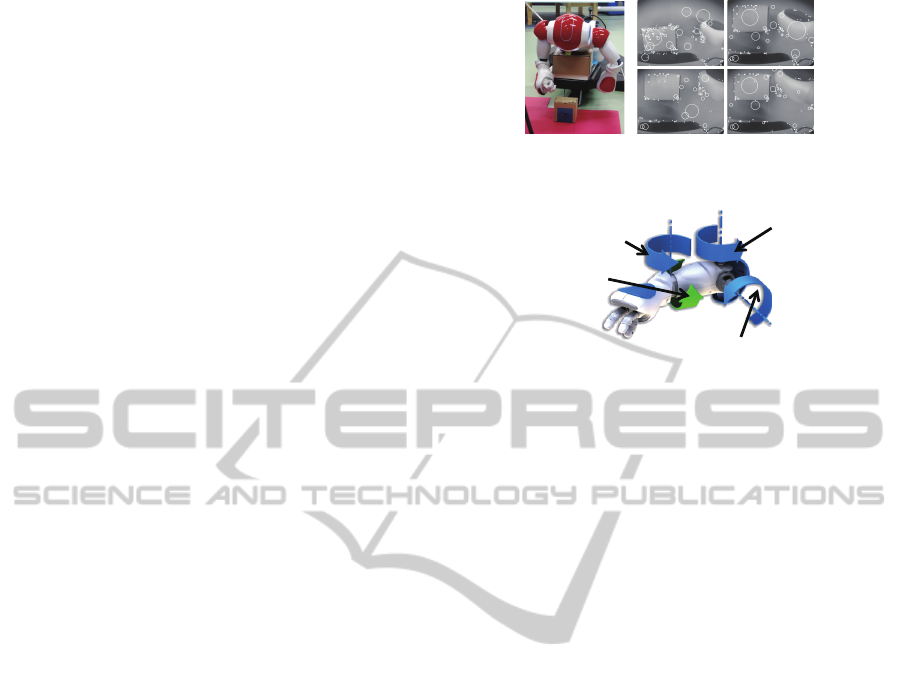
tem, as indicated in Fig. 1. Humanoid robot NAO
Figure 1: Humanoid robot NAO and its image.
Right elbow
roll angle
φ
3
Right shoulder
roll angle
φ
2
Right shoulder pitch angle
φ
1
Right elbow
yaw angle
φ
4
(fixed)
Figure 2: Configuration of robot arm (right).
(Aldebaran Robotics, 2009) is considered both in sim-
ulation and experiment. The images contains part of
body of the robot, an object which can contact with
the robot’s body and background which are not af-
fected by configuration of the robot. The configura-
tion of the robot arm is shown in Fig. 2. Shoulder roll
joint and shoulder pitch joint are controlled (ϕ
1
and
ϕ
2
), while other two joints are fixed throughout the
experiment. This implies that the the motion of the
robot arm is constrained on a plane which is vertical
to optical axis of the CCD camera. A red plane in Fig.
1 is parallel to the motion constraint plane.
Image features are extracted from each image, as
shown as circles in the right hand of Fig. 1. Keypoints
of SIFT (Lowe, 1999) are used as image features. The
robot does NOT have knowledge on properties of im-
age features, that is, the robot does not have labels of
what is object or what is robot’s body in the image in
advance. The robot collects images while changing
configuration of its arm. Position of the object can
also differ irrelevantly to the position of the arm.
Objective of the robot system is to construct a
space which provides the following functions:
1. Estimating closeness of its hand to the object
2. Predicting collision of its hand with the object
The first function allows the robot to plan its hand tra-
jectory so as not to be too close to the object, when
the robot intends to achieve a task while avoiding col-
lision with obstacles. The second function does not
directly allows the robot to avoid collision, but can
contribute to the ability by integration of other tech-
niques, e.g, predition of robot’s hand in the image
space.
IJCCI2013-InternationalJointConferenceonComputationalIntelligence
530
3 MANIFOLD LEARNING USING
IMAGE FEATURES
Manifold learning by LLE is applied to the SIFT key-
points to obtain a continuous space which reflect rela-
tion between the hand and its environment. Each key-
point has 128-dimensional feature vector that can be
utilized for identification and matching to other key-
points. By the matching process, a keypoint can be
traced through multiple images if it is extracted com-
monly in those images. One problem in generating a
vector for manifold learning is that feature vector of
a keypoint is not consistent in different images due to
change of posture of the arm. The arm, which con-
sists of serial links, inevitably change its posture even
when the end of the arm is making translation. Under
an assumption that each keypoint tracks a certain part
of the arm, a method for matching and labeling is pro-
posed using Self Organizing Map (SOM) (Kohonen,
1995).
Let D denote dimension of image vector, N denote
total number of images and I
(i)
∈ R
D
,i = 1,··· ,N de-
note vector of image i. M(i) denote number of key-
points in image i.
3.1 Matching and Labeling of Features
First, image vectors I
(i)
,i = 1, · · · , N are used to gen-
erate a SOM. Let K denotes total number of nodes in
SOM. Image vectors are divided into sets by the nodes
of the SOM.
G(k) = {i|k = argmin
ℓ
∥I
(i)
− w
ℓ
∥
2
}, (3.1)
where w
k
∈ R
D
denotes weight vector of node k. G(k)
denotes set of images that are similar to w
k
. For each
node, a representative image is decided as
¯
i
k
= arg min
i∈G(k)
∥w
k
− I
(i)
∥
2
, k = 1,··· ,K. (3.2)
Image
¯
i
k
is used for generating labels of keypoints.
Labels are generated by Algorithm 1.
As a sequel to the labeling procedure, totally
∑
K
k=1
M(
¯
i
k
) labels are generated.
Although feature vector of a keypoint can differ by
the change of the robot’s configuration, it is likely that
feature vectors in images with small differences are
similar. By using topological neighbor of SOM, cor-
respondence between keypoint labels can be found.
Fig.3 indicates the idea of combining redundant la-
bels. For representative node
¯
i
k
in node k, feature vec-
tors of keypoints are averaged within matched key-
points of images i ∈ G(k). Using the averaged feature
vectors, labels are integrated by Algorithm 2.
Algorithm 1: Labeling of keypoints.
for k = 1 to K do
Select representative image
¯
i
k
for node k
for ℓ = 1 to M(
¯
i
k
) do
Select keypoint ℓ in image
¯
i
k
for i = 1 to N do
if i /∈ G(k) then
Apply SIFT matching with keypoint ℓ to
all keypoints in image i
If matching found, label it
end if
end for
end for
end for
k
'k
)'(kG
)(kG
k
w
SOM
Figure 3: Matching of image features.
By finding correspondence between neighbor
nodes, labels which correspond to the same part of
the real world are integrated into one label.
3.2 Space construction with LLE
Using the obtained labels in the previous section, vec-
tors are defined as follows. Let L denote the number
of integrated labels. Keypoint information of image i
Algorithm 2: Integration of labels.
for k = 1 to K do
Find neighbor nodes of node k as i
′
∈ N (k)
for ℓ = 1 to M(
¯
i
k
) do
for i
′
= 1 to |N (k)| do
Apply SIFT matching with keypoint ℓ by
average feature vector
If matching found, record correspondence
between ℓ and the matched label
end for
If no matching found, remove label ℓ
end for
end for
Integrate all labels using recorded correspondence
ManifoldLearningApproachtowardImageFeature-basedStateSpaceConstruction
531
is converted to vector x
i
∈ R
2L
, where x
i
is defined by
x
i
= [u
(i)
1
v
(i)
1
u
(i)
2
v
(i)
2
··· u
(i)
L
v
(i)
L
]
T
. (3.3)
(u
(i)
ℓ
,v
(i)
ℓ
) denotes position (image coordinate) of key-
point whose label is ℓ in image i. If keypoint whose
label is ℓ does not exist in image i, averages over all
images are used for (u
(i)
ℓ
,v
(i)
ℓ
). Finally, data matrix
for LLE is constructed as H = [x
1
x
2
··· x
N
] ∈ R
2L×N
.
LLE is a method which maps a high-dimensional
vector (2L in this application) to a low-dimensional
vector while preserving local linear structure of each
data around its neighborhood. Weighting coefficient
v
i
j
, j = 1,··· , n for sample i, where n denotes the num-
ber of neighborhood, is calculated so that the cost
function defined by the following is minimized.
ε
1
=
N
∑
i=1
∥x
i
−
n
∑
j=1
v
i
j
x
i
j
∥
2
, (3.4)
where x
i
j
denotes neighborhood sample of x
i
. A low-
dimensional vector y
i
∈ R
d
, corresponding to x
i
, is
calculated so that the following cost function is mini-
mized.
ε
2
=
N
∑
i=1
∥ y
i
−
n
∑
j=1
v
i
j
y
i
j
∥
2
, (3.5)
where y
i
j
, j = 1, ··· ,d denotes neighborhood of y
i
and
d denotes dimension of the low-dimensional space.
4 EXPERIMENT
The proposed representation was evaluated by exper-
iment in two ways, with simulated images and actual
images obtained by a CCD camera attached at the
head of the robot.
4.1 Evaluation with Simulated Image
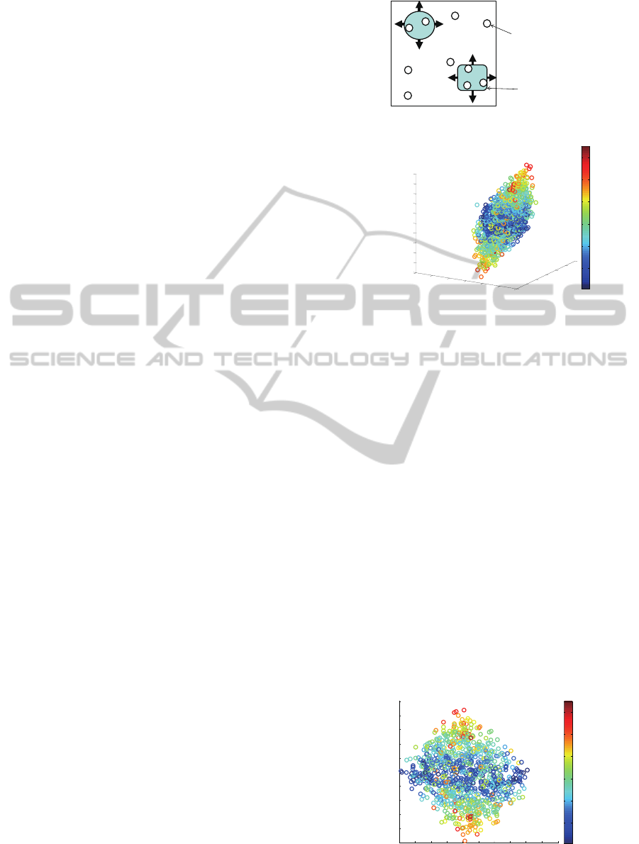
Fundamental property of LLE was tested in condi-
tions similar to the problem setting. Virtual keypoints
are generated as indicated in Fig.4. It was assumed
that an object and the robot hand is captured in a im-
age frame of 400×400 [pix] size. There were 10 key-
points to be detected on the object, 10 on the robot
hand and 5 in background. The positions of the ob-
ject and the hand were varied with uniform distribu-
tion for collecting samples. Total number of images
was set as N = 1000. Number of keypoints was set as
m = 25. Thus, data matrix for LLE was H ∈ R
50×1000
.
Dimension of the mapping was set as d = 3. To sim-
ulate matching error of keypoints, position informa-
tion of 10 % of the keypoints in the data vector were
Object
Robot hand
Keypoint
Figure 4: Simulated keypoints.
䢯
500
䢯
400
䢯
300
䢯
200
䢯
100
0
䢳䢲䢲
䢯
1000
䢯
800
䢯
600
䢯
400
䢯
200
0
200
-500
-400
-300
-200
-100
0
100
200
300
400
500
10
20
30
40
50
60
Y
Y
2
3
Y
1
Figure 5: Distance from object.
removed. That is, 10 % of the elements of H was
replaced by the average value of positions of the cor-
responding keypoint.
The result of mapping by LLE is depicted in Fig.5
and Fig.6. The two figures show the same point in-
formation from different perspectives. The colors of
the points denote distances between the object and the
hand in the corresponding images. It can be seen in
the figure that one direction in the feature space reflect
the distance between the object and the hand.
4.2 Evaluation with Real Image of
Humanoid
The evaluation in the previous section did not include
keypoints extraction and matching. In the experi-
ment with the humanoid robot, the proposed method
described in section was tested. Image size was
-900 -800 -700 -600 -500 -400 -300 -200 -100 0 100
-500
-400
-300
-200
-100
0
100
200
300
400
500
10
20
30
40
50
60
Y
Y
2
3
Figure 6: Distance from object.
IJCCI2013-InternationalJointConferenceonComputationalIntelligence
532
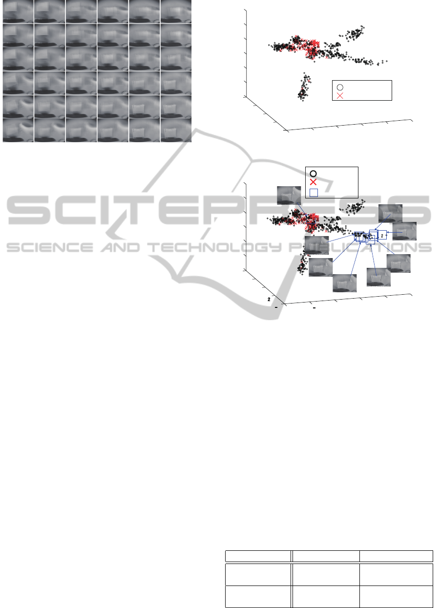
Figure 7: Images corresponding to SOM.
640×480 The number of nodes of SOM was set as
6×6. Joint angles ϕ
1
and ϕ
2
were changed an interval
of 2 [deg]. Position of the object was changed simul-
taneously and totally 732 images were taken.
Fig.7 indicates weight vector of all of the nodes
of SOM. It can be seen similar images are located in
the neighborhood in the topology of the map. After
labeling (Algorithm 1) and integration of labels (Al-
gorithm 2), 1674 labels were obtained.
Fig.8 shows 3-dimensional mapping obtained by
the proposed method. Each point (circle or cross) in-
dicates a vector obtained by converting vector x
i
by
LLE. Cross indicates that the image corresponds to a
situation where the hand is contacting with the object.
Circle indicates that there is no contact. It can be seen
that crosses are concentrating around a certain region.
Distance between the object and the hand, however,
could not be seen in the obtained map.
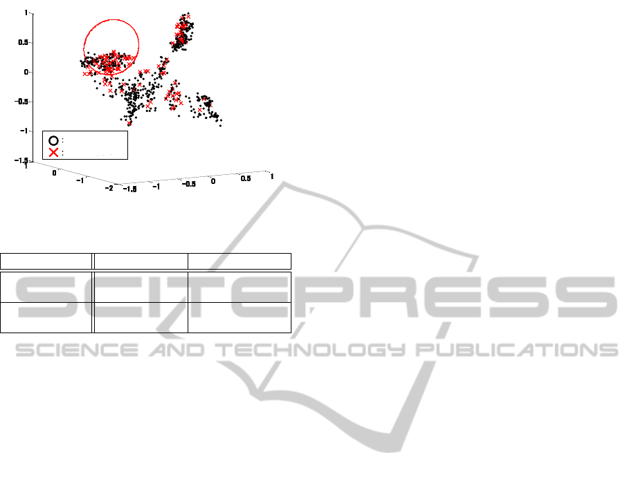
Test images, which were not contained in the im-
ages for training (generating LLE mapping), were
mapped onto the obtained space. Boxes in Fig.9 in-
dicates test samples, where corresponding images are
also displayed. It can be seen that image in which the
hand is the most distant from the object is located at
the furthest from the region with dense crosses. Im-
ages in which the hand is closer are gradually located
closer in the mapped space. But there is a jump at the
last step to contact with the object into the region with
dense crosses.
Using the obtained map, classification of collision
was evaluated. Collision of the hand with the object
was classified by whether a sample is included in the
sphere whose center is the average of the crosses. The
optimal radius was set as r = 0.74. Table 1 shows the
classification result.
For comparison, a linear mapping was also im-
plemented. Fig.10 shows the result of mapping with
PCA (Principal Component Analysis) using the same
data matrix. Crosses, corresponding to contact of the
-2
-1
0
1
2
3
-4
-2
0
2
4
-4
-3
-2
-1
0
1
2
䠖No collision
䠖Collision
Figure 8: Obtained mapping with LLE.
- 2
䢯1
0
1
2
3
䢯4
- 䢴
0
2
4
- 4
- 3
- 2
- 1
0
1
2
䠖Test sample
䠖No collision
䠖Collision
Figure 9: Prediction of collision with test sample.
hand with the object, are more dispersing compared
with Fig.8. Classification result with PCA is shown
in Table 2. It can be seen that consideration of nonlin-
earity brings conspicuous difference of classification
performance.
5 DISCUSSION
The labels of keypoints obtained by the proposed
method was still numerous even after integration of
Algorithm 2. It is possible to consider reliability of
the keypoints by evaluating frequency of appearance.
It should be also considered that there are not so many
Table 1: Discrimination of collision wit LLE.
Collision [%] No collision [%]
Recognized as
collision 95 / 115 [82.6] 111 / 617 [18.0]
Recognized as
no collision 20 / 115 [17.4] 506 / 617 [82.0]
ManifoldLearningApproachtowardImageFeature-basedStateSpaceConstruction
533
No collision
Collision
Figure 10: Mapping result with PCA.
Table 2: Discrimination of collision with PCA.
Collision [%] No collision [%]
Recognized as
collision 63 / 115 [54.8] 132 / 617 [21.4]
Recognized as
no collision 52 / 115 [45.2] 485 / 617 [78.6]
keypoints stably detected on the hand of NAO. Not
only improving reliability of image features (e.g., us-
ing PCA-SIFT (Ke and Sukthankar, 2004)) but also
applying multiple kinds of features will be important
to generate good data matrix.
Mismatching of keypoints is substantially in-
evitable when a part of the robot changes its posture.
Therefore, it will be important to expand the frame-
work to a more flexible one, which can continuously
map a vector whose elements are partly lost.
6 CONCLUSIONS
In this paper, a manifold learning method was tested
for bottom-up acquisition of a space which is useful
for motion generation of a robot. This approach does
not require any specific knowledge on the robot and
its environment, which will contribute to development
of truly flexible intelligence of autonomous robots.
In the evaluation of simulated image vectors, it
was verified that the distance between the robot hand
and the object was reflected in the map. In the evalu-
ation of experiment with real images, the robot could
classify images whether the robot is colliding with
the object based on the obtained mapping. Moreover,
manifold learning turned out to be superior to linear
dimensionality reduction, PCA. As a next step, it will
be required to extend the idea of bottom-up construc-
tion of a low-dimensional space to the case where fea-
tures frequently disappears.
ACKNOWLEDGEMENTS
This work was partly supported by Kayamori Foun-
dation of Informational Science Advancement.
REFERENCES
Aldebaran Robotics (2009). Nao. http://www.aldebaran-
robotics.com/. Technical Specifications Document.
Argall, B. D., Chernova, S., Veloso, M., and Browning, B.
(2009). A survey of robot learning from demonstra-
tion. Robot. Auton. Syst., 57(5):469–483.
Ke, Y. and Sukthankar, R. (2004). Pca-sift: A more distinc-
tive representation for local image descriptors. Com-
puter Vision and Pattern Recognition.
Kobayashi, Y., Okamoto, T., and Onishi, M. (2012). Gen-
eration of obstacle avoidance based on image features
and embodiment. International Journal of Robotics
and Automation, 24(4):364–376.
Kohonen, T. (1995). Self-Organizing Maps. Springer Press.
Lowe, D. G. (1999). Object recognition from local scale-
invariant features. In Proc. of IEEE International Con-
ference on Computer Vision, volume 2, pages 1150–
1157.
Lungarella, M., Metta, G., Pfeifer, R., and Sandini, G.
(2003). Developmental robotics: a survey. Connec-
tion Science, 15:151–190.
Morimoto, J., Nakanishi, J., Endo, G., Cheng, G., Atke-
son, C. G., and Zeglin, G. (2005). Poincar
´
e-Map-
Based Reinforcement Learning For Biped Walking. In
Proc. of IEEE International Conference on Robotics
and Automation.
Oudeyer, P. Y., Kaplan, F., and Hafner, V. (2007). Intrinsic
motivation systems for autonomous mental develop-
ment. IEEE Transactions on Evolutionary Computa-
tion, 11(2):265–286.
Prankl, J., Zillich, M., and Vincze, M. (2011). 3d piece-
wise planar object model for robotics manipulation.
In Robotics and Automation (ICRA), 2011 IEEE In-
ternational Conference on, pages 1784 –1790.
Saul, L. K. and Roweis, S. T. (2003). Think globally,fit
locally : Unsupervised learning of low dimensional
manifolds. Journal of Machine Learning Research,
4:119–155.
Stoytchev, A. (2009). Some basic principles of develop-
mental robotics. IEEE Transactions on Autonomous
Mental Development, 1(2):122–130.
Sutton, R. S. and Barto, A. G. (1998). Reinforcement Learn-
ing: An Introduction (Adaptive Computation and Ma-
chine Learning). A Bradford Book.
Weng, J., McClelland, J., Pentland, A., Sporns, O., Stock-
man, I., Sur, M., and Thelen, E. (2001). Autonomous
mental development by robots and animals. Science,
291:599–600.
IJCCI2013-InternationalJointConferenceonComputationalIntelligence
534
