
A Layered Multi-Agent Model for Multi-Configuration Platoon Control
Baudouin Dafflon, Franck Gechter, Pablo Gruer and Abderrafiaa Koukam
IRTES-SET, UTBM, Belfort, France
Keywords:
Multi-Agent Model, Platoon Control.
Abstract:
Nowadays, urban environments suffer from recurrent traffic jam with associated side effects. Platoon system,
a set of vehicle attach by virtual link, is one of answer. in order to cope with issues such as different platoon
geometrics since several years, we’re seeing the multi-agent system as element of response to many problems.
This paper to apply this concept for platoon vehicles system through an multi-agent model based on key layers.
Thanks this solution, implemented as an agent which makes decisions depending only on its own perception
where each vehicles is recorded, analysed, transform in car command and adapted to vehicle by a command
filter.
1 INTRODUCTION
Platoons can be defined as a set of autonomous vehi-
cles evolving on a particular environment while main-
taining a particular geometric configuration. Platoon
control consists in determining the behaviour of each
one of the vehicles during platoon evolution, in order
to maintain the configuration and adapt it to changes
in the terrain (presence of unanticipated obstacles, de-
creasing of available surface, ...).
Several international projects, past or present, address
platoon control. Among them, we can cite PATH
(Hedrick et al., 1994), SARTRE (Chan et al., 2011),
CRISTAL
1
, SAFEPLATOON (Cartade et al., 2002)
2
. Most of them deal with column platoons as unique
configuration and situate in well defined environment
such as highways where the curve radius are high and
where the speed can be considered to be constant most
of the time. However, other application domains,
placed in different kinds of environments could bene-
fit from platoons composed of different types of vehi-
cles. Among those application domains we can men-
sion transportation and maintenance operations in ur-
ban areas, labouring and harvesting in agricultural ar-
eas and military operation theatres. Those cases are
subject to diverse, more stringent constraints. As an
example, in urban areas with a column configuration,
the lateral error must be highly limited in order to
avoid collisions. In echelon or line configurations, en-
vironment related constraints are more influential.
1
http://projet-cristal.net/
2
http://web.utbm.fr/safeplatoon
In this paper, we propose an multi-agent based ap-
proach for the multi-configuration platoon control
problem. The approach can be considered as self-
organizing, because platoon configuration emerges
from the behaviour of each vehicle, strictly based on
local vehicle’s perceptions. The platoon’s configura-
tion is determined locally by assigning to any platoon
vehicle another neighbouring platoon vehicle, consid-
ered as local leader. This proposal is structured as
a multi-layer decision process dealing first with the
interpretation of the perception data, then integrating
the choice of the local leader depending on the in-
tended spatial configuration and finally producing a
kinematic decision that has to be performed by the
vehicle. In this approach, each vehicle is consid-
ered as an agent which bases on its perceptions and
on the local intended configuration to make the cor-
rect decision. The proposed approach integrates ob-
stacle avoidance abilities which is based on a multi-
agent filtering method similar as the one developed in
(Franck Gechter and Koukam, 2010).
The paper is structured as follow: after a short re-
minder about vocabulary, a state of the art on platoon
systems is proposed. Then, the multi agent system ap-
plied to platoon control is described. Finally, a con-
clusion and some considerations on future work di-
rections are presented.
33
Dafflon B., Gechter F., Gruer P. and Koukam A..
A Layered Multi-Agent Model for Multi-Configuration Platoon Control.
DOI: 10.5220/0004632500330040
In Proceedings of the 10th International Conference on Informatics in Control, Automation and Robotics (ICINCO-2013), pages 33-40
ISBN: 978-989-8565-70-9
Copyright
c
2013 SCITEPRESS (Science and Technology Publications, Lda.)
2 DEFINITIONS
The literature introduces a rich terminology in related
to the platoon domain. In this section, we intend to
present the vocabulary used along the work, in order
to avoid ambiguities.
2.1 Leaders
Vehicles with a distinctive role within the platoon are
frequently qualified as leaders. We distinguish two
kind of leader roles.
Global Leader. The global leader is the reference ve-
hicle of the entire platoon. It can be fully autonomous,
applying a path-following algorithm, or driven by a
human operator. The global leader determines the ref-
erence trajectory for the convoy. Local Leader. The
local leader notion is tied to local, self-organizing ap-
proaches, and corresponds to the vehicle taken as a
reference by a follower vehicle. Each vehicle in the
platoon has a local leader, but this role can be assigned
dynamically during platoon operation. Generally, the
local leader is taken among the closest vehicles in the
follower perception field.
Virtual Leader. The notion of virtual leader is tied to
the mechanisms involved in our methods. The princi-
ple developed in this paper, is to be able to transform
any spatial configuration into a local column config-
uration of a local leader and its follower, and to ap-
ply a well defined interaction model, to determine fol-
lower’s behaviour.
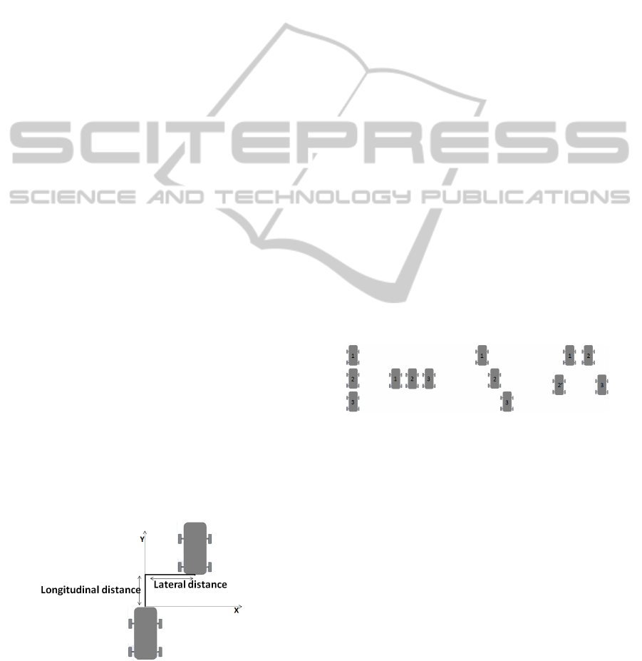
2.2 Geometry
A platoon configuration geometry is defined by means
of two distances, lateral and the longitudinal (cf.
Fig.1). The Lateral distance represents the lateral
spacing between two neighbour vehicles. The Lon-
gitudinal Distance. represents the spacing between
two neighbour vehicles, in the direction of the move.
Figure 1: Lateral and longitudinal distances.
Configuring a platoon formation bases on the defi-
nition of both lateral and longitudinal distance. De-
pending on the values of these, several platoon con-
figuration can then be defined, among which we can
mention: Column Configuration. This configura-
tion, represents the most frequently studied form of
platoon where vehicles organize as train (cf.figure
2). In this configuration, lateral distance should re-
main as small as possible (for curved trajectories this
means mono-trace displacement). Column configu-
rations have been foreseen as mostly dedicated for
the transport of passengers in urban or highway trans-
portation systems.
Line Configuration. In this configuration, vehicles
are placed side by side (cf.figure 2). The longitudinal
distance must be null. This configuration can be ap-
plied to agricultural tasks, such as tilling.
Echelon Configuration. Vehicles are in an inclined
column configuration, each is offset from the preced-
ing by a lateral distance (cf.figure 2). In this configu-
ration, lateral and longitudinal nominal distances have
a specified, non null value. This configuration can be
dedicated to agricultural or military applications.
Arbitrary Configuration and Wedge Configura-
tion. Arbitrary configurations can hold many geomet-
rical forms, produced by the combinations of two or
three of the configurations described above. These
configurations are mostly used in military environ-
ments. In wedge configuration for instance, leader
vehicle is followed by echelons of vehicles placed to
the right and the left forming an inverted ”V” forma-
tion (cf. figure 2).
Figure 2: Configurations of platoon. From left to right: col-
umn, line, echelon, wedge.
3 STATE OF THE ART
Platoon control approaches can be sorted into two
main categories: local approaches base on a local ref-
erence frame. On the other hand, global approaches
base on a global frame, common to every vehicle in
the platoon.
3.1 Local Approaches
Local approaches are based on a local reference frame
which generally anchors in the follower vehicle. In
this frame, the position and the orientation of the local
leader can be determined in the local frame. Conse-
quently, the local approach can be considered as the
ICINCO2013-10thInternationalConferenceonInformaticsinControl,AutomationandRobotics
34
regulation of both lateral and longitudinal distances
between the follower and its local leader.
Among the proposals corresponding to this ap-
proach, we can mention:
• System based on an automatic control mecha-
nism: (Daviet and Parent, 1996) proposes a mech-
anism for local control based on a PID (Propor-
tional, Integral, Derivative) controller . The mea-
surement acquisition is performed by linear cam-
eras or by a range finder sensor (Riess, 2000). The
control reference is decomposed on one hand in a
longitudinal reference and on the other hand in a
lateral reference.
• Control based on undumped impedances: (Gehrig
and Stein, 2001) presents a model of light links
where vehicles are treated as particles subjected
to physical forces.
• Control model based on a double impedance con-
trol: in (o Yeong Yi and Chong., 2005) an
impedance control model is used as a model of
the immaterial link between vehicles.
• Control based on a virtual mechanical link: In
these approaches, each vehicle in the convoy is
designed as an intelligent system able to perceive
its environment and maintaining a pre-set distance
with the preceding vehicle. The platoon system is
the result of direct interaction between each vehi-
cle and its predecessor. This approach is based on
an interaction model inspired by the physics. In-
deed, the interaction between two successive ve-
hicles virtual link shown by a mass-spring type.
Among these one can cite (Franck Gechter and
Koukam, 2010).
3.2 Global Approaches
Each vehicle determines its control references de-
pending on a global shared reference. Platoon trajec-
tory is determined by the global leader and expressed
as a series of trajectory points situated in the global
reference frame, known by every vehicle. The shar-
ing of the trajectory points implies vehicle to vehi-
cle communication capabilities and high performance
global localisation devices aimed at determining the
position of each vehicle in the global reference frame.
Platoon control can be considered as the regulation of
both lateral and longitudinal distance between each
vehicle and the reference trajectory.
Among the proposals corresponding to this ap-
proach, we can mention:
• An optimal controller is proposed in (Levine and
Athans., 1966) to serve on a constant set of inter-
vehicle distance in columns moving at high speed.
• In (Caicedo et al., 2003), the formation is char-
acterized by a set of generalized coordinates de-
scribing the position and the orientation. The re-
sulting shape and evolution of the column is based
on the laws of mechanics.
Relatively to military platoons enumerated, these
can fit the global/local classification. Unit center ref-
erenced and leader referenced approaches can be con-
sidered as global (the control can be centralized or de-
centralized). By contrast, Neighbour-referenced tech-
nique is local and decentralized.
4 MULTI LAYERS DECISION
PROCESS
4.1 Global Overview
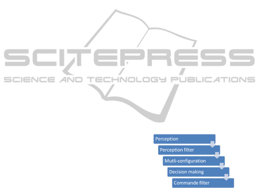
Our proposal is based on a multi-layer systems for
decision making. This architecture provides a set of
5 plug and play units (cf. Fig 3). The principle de-
veloped is based on the transformation of any spatial
configuration into a column configuration which uses
a well defined interaction model. Then, we use a vir-
tual leader, the position and the orientation of which
correspond to the transformation of the local leader
position and orientation taking into account platoon
spatial desired configuration.
Figure 3: Multi-layer Architecture.
Each step of the process is independent and has got
specific parameters and can be defined as follow :
Perception. is an abstraction of sensors. The in-
put data are the raw information from the sensors. A
parser is used to convert them in workable data set for
further decision-making process
In Perception Filter. block a filtering policy is ap-
plied. The goal of this unit is to sort out the perceived
elements between obstacles and other convoy vehi-
cles. Among these vehicles a local leader is chosen
using specific strategy.
The Multi-Configuration. unit applies the geomet-
rical transformations required to change local leader
position and orientation into virtual leader ones.
ALayeredMulti-AgentModelforMulti-ConfigurationPlatoonControl
35
The Decision-Making. block corresponds to the ap-
plication of the interaction model and the computing
of the command law to be applied to the vehicle.
The last step in this process is an Command Filter-
ing. which can corresponds to driving assistance fil-
tering such as obstacle avoidance or to the introduc-
tion of a kinematic model for the smooth command
for instance.
4.2 Detailed Description
This section aims at describing layers one by one fol-
lowing the introduction description and figure 3.
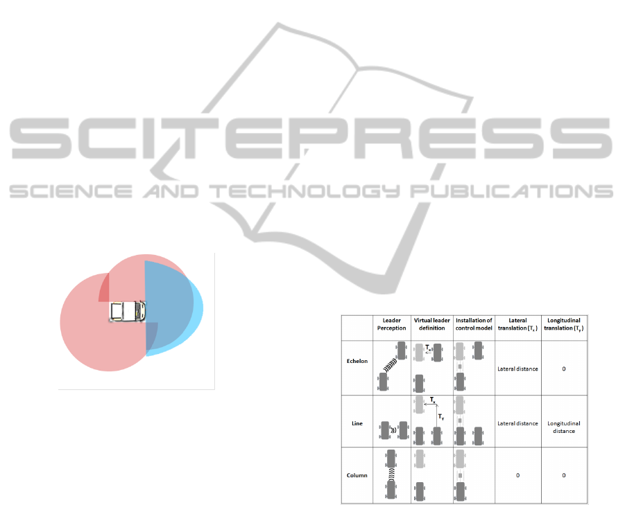
4.2.1 Perception
The perception takes as an input the raw data of the
sensor associated to object detection algorithm. To be
able to have reliable detection, sensors have to cover
the surrounded environment of the vehicle as shown
in fig. 4. The output of the perception unit is a list of
localized object in the vehicle reference frame. Vari-
ous kind of sensors can be used to performed this pro-
cess such as stereo cameras, sonars belt, laser range
finders,...
Figure 4: Sensors ideal coverage area.
4.2.2 Perception Filter
The goal of this unit is to analyse the output of the
perception in order to remove noise in the data and to
sort out detected objects. A Kalman filter has been
chosen to filter the noise. A Kalman filter is a pre-
diction/correction based filter which uses a transition
model for the prediction and an observation model for
the correction. As for the sorting of the objects a sim-
ple strategy has been used. the aim is to provide a
classification of the environment in 3 class.
1. Object member of convoy
2. Object moving in same direction but not member
of convoy
3. Object moving perilously.
This classification is based on dynamic study of per-
ceived object.
Then, the final step of this filtering unit is a geomet-
rical transformation aimed at expressing the coordi-
nates of the detected objects into the vehicle reference
frame. (Initially, their coordinates are expressed into
the sensors reference frames)...
4.2.3 Multi-Configuration
As exposed before, each vehicle in the platoon can
be seen as an agent that acts based only on its per-
ceptions. For each agent, we define a leader among
its neighbours in the platoon (see section 4.2.2). The
agent computes its references based on the position of
its leader by trying to maintain the desired lateral and
longitudinal spacing and the correct orientation. Col-
umn formation platoon control functions are now well
known and expose reliable properties. Consequently,
it as been decided to base our approach on this el-
ementary function. So, the key step is to translate
leader local position in vehicle agent reference frame
in order to be able to use column platoon function and
integrates desired lateral and longitudinal distances.
As exposed in section 2, there are several types of
configuration that can be grouped into several fam-
ilies (echelon, line, column). The multi configura-
tion proposal is based on modification of perception
by introduction of virtual leader vehicle. Indeed, as
detailed in table 5, every formations are possible with
the introduction of a virtual leader.
Figure 5: Formations tab.
In order to determine position of virtual leader, sev-
eral parameters are used: geometrics aspects, percep-
tion and configuration order. Indeed, a translation of
la and lo is made in the referential of local leader.
Position of virtual leader is defined by a 2D Trans-
formation (figure 6) could be describe by following
equation :
x
v
= x
r
+ l
a
cos(θ) +l
o
sin(θ)
y
v
= y
r
− l
a
sin(θ) + l
o
cos(θ)
(1)
where
ICINCO2013-10thInternationalConferenceonInformaticsinControl,AutomationandRobotics
36
• (x
v
,y
v
) virtual leader position
• (x
r
,y
r
) real leader position
• (l
a
,l
o
) lateral and longitudinal distances
• θ angle between cars.
Figure 6: Virtual leader in multi configuration.
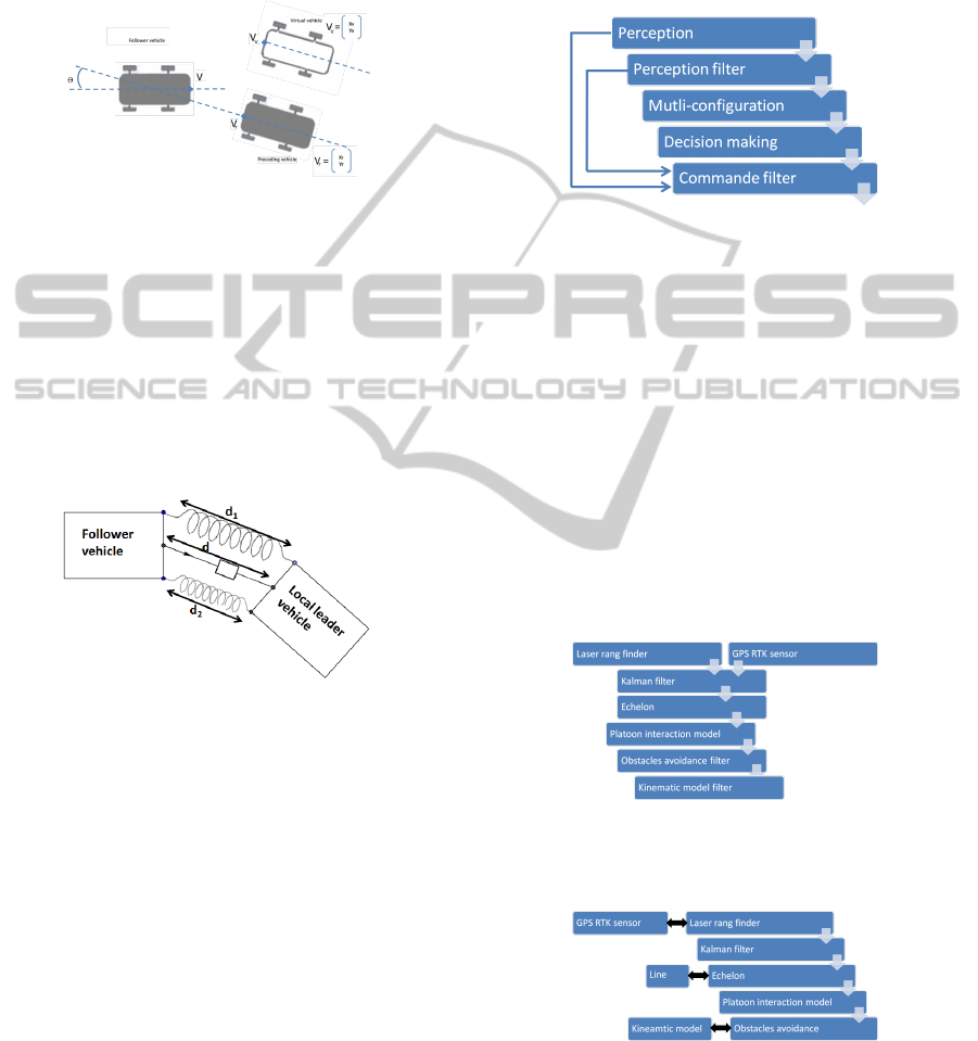
4.2.4 Interaction Model
A model of interaction inspired by physics has been
chosen. This model, detailed in (El-Zaher et al.,
2011b) has got two springs and a damper placed
between the local leader and the follower vehicle
(cf Figure 7). This model is virtual and unidirec-
tional. Indeed to better control the interaction, the lo-
cal leader vehicle is not affected by generated forces.
Figure 7: Interaction model.
The parameter of this model take into account the
vehicles characteristics . This optimisation allow to
keep a low latency and keep a real-time reactivity.
A compositional verification of this system has been
made in (El-Zaher et al., 2011a) to prove non collision
event.
4.2.5 Command Filter
The command proposed by the interaction model
must be adapted to the environment in order to deal
with the presence of obstacles for instance. Several
filters can be considered. The most simple is an emer-
gency stop filter: in case of obstacles in a neighbour-
hood too close, the command is set to 0. Another
filter presented in previous work (Franck Gechter
and Koukam, 2010) and aimed at computing obsta-
cle avoidance strategies can be apply. This obstacle
avoidance device is based on a multi-agent system
where the observation of an agents population lead
to a modification of the vehicle command.
These filters require data from the perception.
This is why a link is possible to bring directly sen-
sors data from perception unit (or perception filter) to
command filter as shown in the picture 8.
Figure 8: Command filter input.
4.3 Flexible and Adaptive System
As seen above, our proposal is based on layers. Each
module takes, as an input, the output of preceding
block. Thus, provided that the input and the output are
correct, layers can be changed using other algorithms
or strategies. Moreover, it is possible to combined
some inputs or to combine in cascade several blocks
of the same type. Finally, these changes in blocks can
be performed in runtime
Here are two examples to illustrate this modular-
ity:
1. Input combined and association in cascade
Figure 9: Input combined.
2. Interchanged blocks:
Figure 10: Association in cascade.
ALayeredMulti-AgentModelforMulti-ConfigurationPlatoonControl
37

5 EXPERIMENTAL RESULTS
5.1 Global Overview
5.1.1 Vehicles Description
Vehicles used in the simulation represent (graphi-
cally and physically) the experimental laboratory’s
vehicles. They satisfy the physical constraints and
share the same characteristics. In simulation, they
are equipped with two 270 degrees virtual laser range
finder, replica of LMS SICK 200 and with GPS-
RTK simulation required to follow and study trajec-
tories. Vehicles have the following characteristics:
1.8m width, 3.05m length, max steering angle=30 de-
grees and max speed=12m/s
5.1.2 Simulator
To assess the quality of our approach, simulations
have been done using VIVUS simulator (Lamotte
et al., 2010), VIVUS is a vehicle simulator based on
PhysX for real physical behaviour developed by the
SeT
3
laboratory.
This software can simulates behaviours for each ve-
hicle such as perception with laser range finder or
cameras, physical reaction between elements (wheels,
car’s parts,...),... Physical reaction are computed us-
ing the same physical law as real world (collision,
gravity,...) and considering the peculiarity of the en-
vironment (friction with soil, materials of soils and
walls,...). VIVUS has already been used to test vari-
ous intelligent vehicle algorithms such as linear pla-
toon control (Franck Gechter and Koukam, 2010) and
(El-Zaher et al., 2011b), obstacle avoidance and driv-
ing assistance (Gechter et al., ) and (Dafflon et al.,
2012), and intelligent crossroads simulations in (Daf-
fon et al., 2011).
5.1.3 Metrics and Analysis
Two informations are measured during experimenta-
tions:
• Lateral distance measures the spacing between the
horizontal axes of two neighbour vehicles. In
cases of column platoon, this distance should be
null.
• Longitudinal distance represents the inter-vehicle
distance between two neighbour vehicles.
Lateral and longitudinal distances are recorded by
VIVUS simulator and analysed off-line by matlab
scripts. thanks to these measures, we will explore:
3
http://set.utbm.fr/
- General behaviour of the convoy route with GPS -
Lateral and longitudinal distances a function of time -
Lateral and longitudinal distances a function of speed.
5.1.4 Test Area
Simulations were performed on a 3D geo-localized
model of the city of Belfort (France). Two different
trajectories have been chosen. In the first trajectory,
vehicles have to follow a circle around 25m of radius.
The simulations are done many times (ie: 500 itera-
tions) for the purpose a statistical studies about exper-
imentations.
5.2 Experimental Results
Experimentations are made following two scenarios.
The first simulates a convoy of vehicles in the column
whereas the second simulates a echelon convoy.
5.2.1 5 Vehicle Platoon Convoy in Column
1. 5 vehicle platoon convoy in line :
In Figure 11, only the lateral gaps from the first,
third, fourth and last follower are presented. We
can see that the error between the measurement
and instruction is amplified depending on the po-
sition of the vehicle in the convoy. The last fol-
lower error is between 0.07m and 0.55m, while
the first follower error is between 0.12m and
0.01m. The difference between the measurement
and setpoint comes from amplification errors due
to the local approach. It is interesting to compare
these measures to the width of a tire (about 0.2 m).
Figure 11: Lateral Gap in Platoon Convoy.
In Figure 12, only the longitudinal gaps from the
first, third and last follower are represented. We
can see that the error between the measurement
and set point is amplified. The error of first fol-
lower is between 5.7m and 6.7m whereas the last
follower is between 5.2 m and 6.4 m. The differ-
ence between the measurement and the reference
is from an extension of the springs in the present
interaction model.
2. 5 vehicle platoon convoy in echelon
Figure 13 shows the lateral deviation follower 1
and 5. We notice that the echelon formation does
ICINCO2013-10thInternationalConferenceonInformaticsinControl,AutomationandRobotics
38
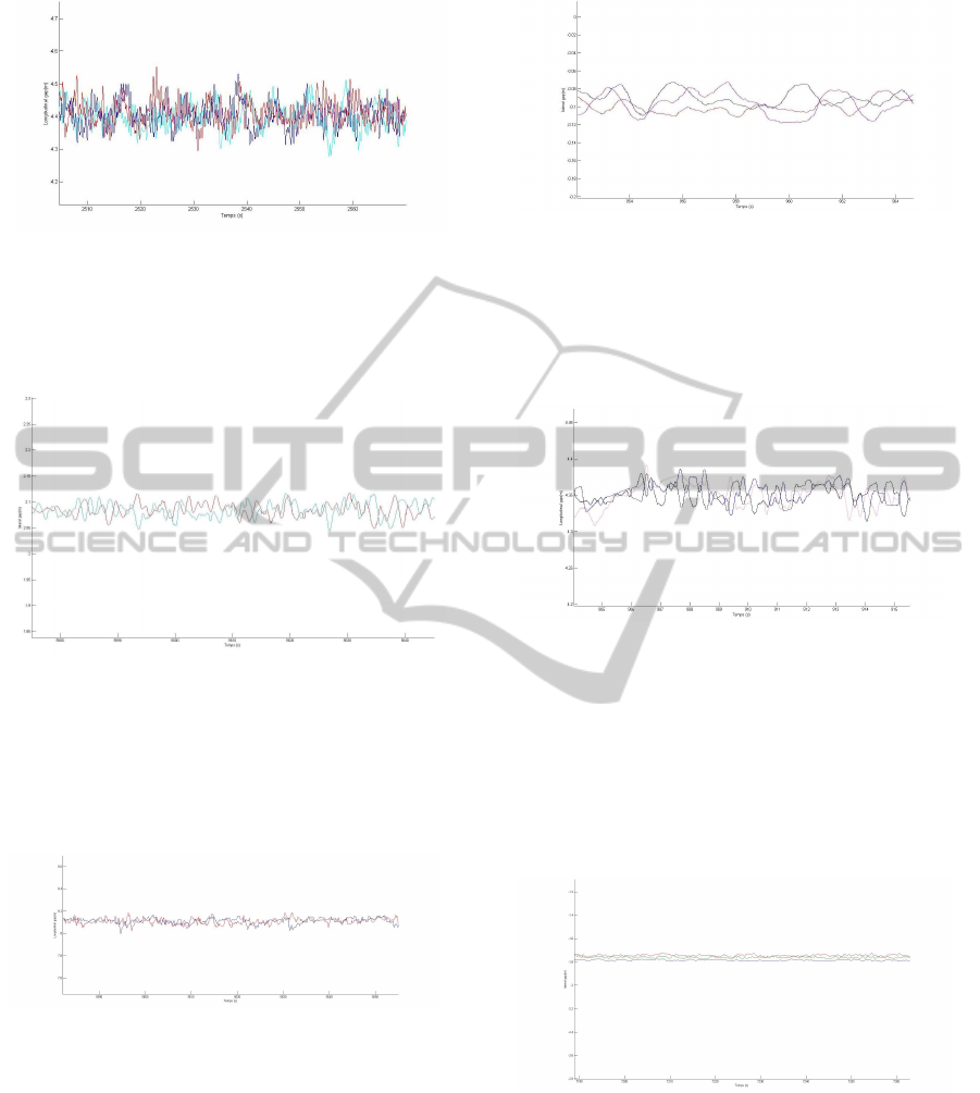
Figure 12: Longitudinal Gap in Column Platoon Con-
voy.
not lead additional oscillation as compared to a
column formation. The virtual vehicle seems a reliable
alternative for the inter-distance management of a
multi-lateral configuration.
Figure 13: Lateral Gap in Echelon Platoon Convoy.
Figure 14 shows the longitudinal inter-distance mea-
sured on the train. We can notice that the error between
the measurement and set point spreads by amplifying.
The inter-distance of first follower is between 5.18m
and 5.2m while the last follower is between 5.01m and
5.22 m.
Figure 14: Longitudinal Gap in Echelon Platoon Con-
voy.
5.2.2 5 Vehicle Platoon Convoy in Circle
1. 5 vehicle platoon convoy in column
As shown in Figure 15 the differences between
first and last follower, we can see besides the
residual oscillations that the differences between
vehicles are of the same order as in previous ex-
periment. From the first follower to the last,
the longitudinal gap is in a range from 5.87m to
6.04m.
Figure 15: Lateral Gap in Column Platoon Convoy.
Figure 16 represents the lateral error from the first
follower to the last. Thus, while the measurement
of the first Follower are in the same order as be-
fore, the last follower describes an lateral error be-
tween -0.1 and 0.2m.
Figure 16: Longitudinal Gap in Column Platoon Con-
voy.
2. 5 vehicle platoon convoy in echelon
Figure 17 describes the evolution in time of the lateral
deviations. it may be noted that the position in the con-
voy does not increase the oscillations. Indeed, with a
circular path, the error is comprised between 0.09 and
0.11m (less than the width of a tire). It is interesting to
note that the train keeps the same stability with 3 to 5
vehicles.
Figure 17: Lateral Gap in Echelon Platoon Convoy.
Figure 18 shows that the most the vehicle is near the
center, the more the error on the longitudinal set point
is large. The reasons of this result are the links between
anticipation, speed elongation and virtual vehicle trans-
formation.
ALayeredMulti-AgentModelforMulti-ConfigurationPlatoonControl
39

Figure 18: Longitudinal Gap in Echelon Platoon
Convoy.
6 CONCLUSIONS
The paper presents a agent approach for platoon sys-
tem through a generic and modular decision process
for autonomous vehicle in platoon system. In this
model, different layer is are proposed and combined
to define behaviour. Each layer allow facilitate the
processing done in next step. The main advantages
proposed by this system is a run time and self adap-
tation to environment. This solution was successfully
tested in simulation and results obtained are encour-
aging to test using real laboratory vehicles and real
sensors. In order to continue this research, we are now
working on generic and emerging perception filter to
adapt perception to any sensors.
Those works are done with the support of the
French ANR (National Research Agency) through the
ANR-VTT SafePlatoon
4
project (ANR-10-VPTT-
011).
REFERENCES
Caicedo, R., Valasek, J., and Junkins, J. (2003). Preliminary
results of one-dimensional vehicle formation control
using structural analogy. Control Conference.
Cartade, P., Lenain, R., Thuilot, B., and Berducat, M.
(2002). Formation control algorithm for a fleet of mo-
bile robots. 3rd International Conference on Machine
Control and Guidance.
Chan, E., Gilhead, P., Jelinek, P., and Krejci, P. (2011).
Sartre cooperative control of fully automated platoon
vehicles. 18th World Congress on Intelligent Trans-
port Systems.
Dafflon, B., Contet, J.-M., Gechter, F., and Gruer, P. (2012).
Toward a reactive agent based parking assistance sys-
tem. The 24rd IEEE International Conference on
Tools with Artificial Intelligence ICTAI, IEEE Com-
puter Society.
Daffon, B., Gechter, F., Contet, J., Abbas-Turki, A., and
Gruer, P. (2011). Intelligent crossroads for vehicle
4
http://safeplatoon.utbm.fr
platoons reconfiguration. International Conference on
Adaptive and Intelligent Systems.
Daviet, P. and Parent, M. (1996). Longitudinal and lateral
servoing of vehicles in a platoon. IEEE Intel ligent
Vehicles Symposium, pages 41 – 46.
El-Zaher, M., Contet, J., Gruer, P., and Gechter, F. (2011a).
Towards a compositional verification approach for
multi-agent systems : Application to platoon system.
First International workshop on Verification and Val-
idation of multi-agent models for complex systems
(V2CS).
El-Zaher, M., Gechter, F., Gruer, P., and Hajjar, M. (2011b).
A new linear platoon model based on reactive multi-
agent systems. The 23rd IEEE International Confer-
ence on Tools with Artificial Intelligence ICTAI, IEEE
Computer Society.
Franck Gechter, Jean-Michel Contet, P. G. and Koukam, A.
(2010). A reactive agent based vehicle platoon algo-
rithm with integrated obstacle avoidance ability. Self-
Adaptive and Self-Organizing Systems.
Gechter, F., Contet, J., Gruer, P., and Koukam, A. Car driv-
ing assistance using organization measurement of re-
active multi-agent system. Procedia CS1(1): 317-325.
Gehrig, S. and Stein, F. (2001). Elastic bands to enhance
vehicle following. IEEE Conference on Intelligent
Transportation Systems, pages 597 – 602.
Hedrick, J., Tomizuka, M., and Varaiya, P. (1994). Control
issues in automated highway systems. Control Sys-
tems, IEEE, 14(6):21 –32.
Lamotte, O., Galland, S., Contet, J.-M., and Gechter, F.
(2010). Submicroscopic and physics simulation of
autonomous and intelligent vehicles in virtual reality.
Advances in System Simulation, International Confer-
ence on, 0:28–33.
Levine, W. and Athans., M. (1966). On the optimal error
regulation of a string of moving vehicles. IEEE Trans-
actions on Automatic Control.
o Yeong Yi, S. and Chong., K.-T. (2005). Impedance control
for a vehicle platoon system. Mechatronics.
Riess, R. (2000). Qualification d’un tlmtre balayage laser
pour la robotique mobile : Intgration et exprimenta-
tions. Master’s thesis.
ICINCO2013-10thInternationalConferenceonInformaticsinControl,AutomationandRobotics
40
