
On the Investigation of Lumped Parameter Models for Thermal
Characterization of High Power Modules
Marco Iachello
Dipartimento di Ingegneria Elettrica Elettronica e Informatica, Facoltà di Ingegneria, Università degli studi di Catania,
viale A. Doria 6, 95125 Catania, Italy
Keywords: High Power Modules, Thermal Modeling, Thermal Coupling, Lumped Parameter Models, Distributed
Parameter Models.
Abstract: This research focuses on the development of a new thermal modelling methodology of multichip electronic
power modules. The current stage of the research is intermediate. In the first step the implementation of
simulations for collecting thermal data on high power modules has been performed. The current step is the
development of the methodology for lumped parameter models extraction. The main aim of this project is to
generate an optimized procedure for the design of lumped parameter thermal models extracted from 3D-
field simulations or experimental measurements
1 STAGE OF THE RESEARCH
This research focuses on the development of a new
thermal modelling methodology of multichip
electronic power modules. The current stage of the
research is intermediate. In the first step the
implementation of simulations for collecting thermal
data on high power modules has been performed.
The current step is the development of the
methodology for lumped parameter models
extraction.
2 OUTLINE OF OBJECTIVES
The main aim of this project is to generate an
optimized procedure for the design of lumped
parameter thermal models extracted from 3D-field
simulations or experimental measurements.
3 RESEARCH PROBLEM
The growing demand of high power devices
concentrated in small volumes is leading to the
design of integrated power modules. They are
realized by integrating several chips inside one
package. Consequently the resulting high power
density produces strong thermal constraints on the
package. Furthermore, the different chips included
in the device are thermally coupled, then the thermal
power provided by each chip has the effects of
heating the chip itself and all the other chips in the
package. Thermal aspects become dominant and
strongly influencing either the module working
conditions or its lifetime. As a result the probability
of failures, due to the thermal stresses, significantly
increases, thus impacting on the reliability. Then to
keep the device in safe operating conditions, the
silicon chips junction temperature (both in transient
and in steady-state regime) should be known and
controlled. On the one hand, thermal simulators need
to be more and more able to reproduce
instantaneously the device thermal behaviour. On
the other hand, if there are more than just a few
chips thermally modelled the simulation time of
three dimensional models increases enormously. The
result is that a trade-off is necessary. This research
addresses the problem to reproduce the thermal
behaviour of high power modules by means of
equivalent circuit simulators.
4 STATE OF THE ART
Many papers describing numerical methods for
thermal analyses of multichip power modules have
been published (Wu et al., 2013); (Shammas et al.,
3
Iachello M. (2013).
On the Investigation of Lumped Parameter Models for Thermal Characterization of High Power Modules.
In Doctoral Consortium, pages 3-7
DOI: 10.5220/0004636900030007
Copyright
c
SciTePress

2002). In general it is possible to classify them in
two main categories: approaches based on
distributed parameter models and on lumped
parameter models.
4.1 Distributed Parameter Models
Distributed parameter models are characterized by
the fact that all variables are both function of time
and function of some spatial coordinates.
Assuming constant thermal conductivity, the heat
conduction inside a volume domain is described by
the following equation (Cengel, 2002):
1
(1)
where is the time, the temperature field, the
thermal diffusivity, is the thermal conductivity and
the rate of the internal heat generation per unit
volume. The equation (1) can be solved employing
different methods as the Finite Element Method
(FEM) and the Boundary Element Method (BEM).
These approaches, which can be described as
physical modelling, entail decomposing the device
geometry into a collection of volume (FEM) or
surface (BEM) elements (meshing), and then solving
a system of partial differential equations for the field
values at the element control points.
The problem is completed assigning initial and
boundary conditions.
Typically power modules are made by thin
vertical layers and have large horizontal dimensions.
It means that the heat flux predominantly flows from
the top to the bottom of the module. Consequently
the flux through the lateral sides could be neglected
and the corresponding boundary condition assigned
is adiabaticity.
If the heat sink is dimensioned properly, it will
be able to dissipate the whole heat and its bottom
side could be assumed isothermal.
Let us consider a power module made up of
chips and focus our attention on its FEM thermal
modelling.
As explained in (Khatir et al., 2004), the heat
transfer problem could be assumed linear and this
hypothesis is in good approximation true for most
power electronic applications. Under these
conditions the superposition principle is applied.
The usual approach (Drofenik et al., 2007);
(Carubelli and Khatir, 2003) consists in applying a
power pulse (
) only on a single chip and to
measure thermal responses on all chips. The
temperature of the bottom side of the heat sink is
called reference temperature (
). The approach is
schematically shown in Figure 1.
Figure 1: A prototypal version of a power module made of
6 IGBTs and 6 diodes.
To characterize the response of the heated chip,
the so-called thermal self-impedance is defined:
,
(2)
where
is the power applied on chip and
is the
temperature of the centre, on the top area, of the
heated chip .
The thermal coupling effect between chips is
given from the thermal mutual-impedance defined
as:
,
(3)
where
() is the temperature of the centre of
chip when chip is heated by the power
.
Then, for a device having chips, it is possible to
assemble the following thermal impedances matrix:
,
,
⋯
,
,
⋮⋱⋮
,
,
⋯
,
,
(4)
in which the coefficients of the main diagonal are
the self-impedances of each silicon chip while the
other terms are the mutual-impedances describing
coupling effects between chips.
It is important to underline that thermal
impedances can be calculated from 3D thermal
model or extracted from experimental
measurements.
Combining equations (2)-(4), the complete
model can be written in matrix-form as:
(5)
where
is the thermal impedances matrix, P
is the 1 vector of the input powers
and is
a 1 vector of the differences between the
temperature chip
and the reference temperature
ICINCO2013-DoctoralConsortium
4
.
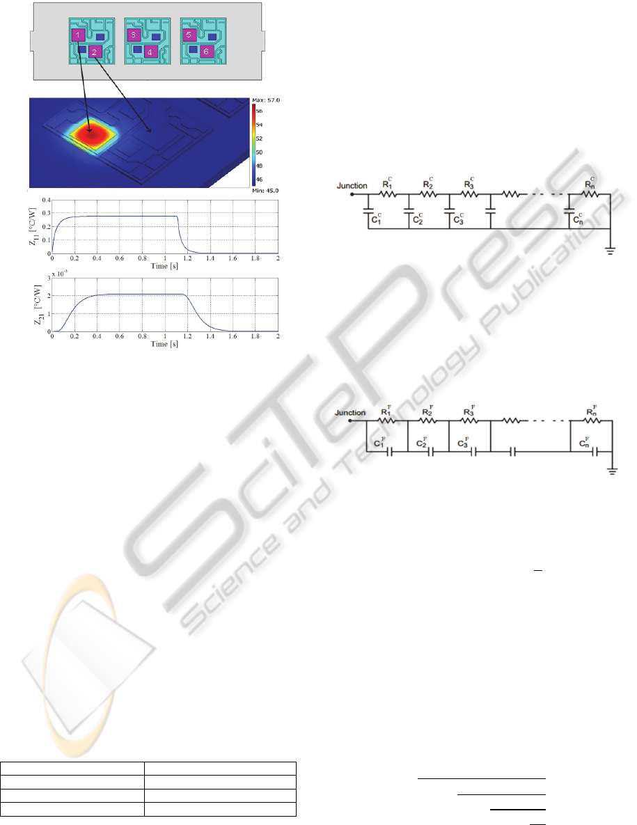
(a)
(b)
Figure 2: (a) Colormap of a 3D COMSOL Femlab thermal
simulation. (b) Thermal self-impedance Z
11
(t) and mutual
thermal impedance Z
21
(t) extracted from the simulation.
Figure 2 shows an example of the result of the
methodology described above applied to a power
module prototype. In this case the chip 1 is heated
(Figure 2a) and the response of the chip 1 itself and
of the chip 2 have been extracted.
Comparing the thermal impedances in Figure 2b
the presence of a delay in the mutual impedance is
evident.
Although 3D numerical simulations are very
accurate, they can require very high computational
cost and long simulation times.
4.2 Lumped Parameter Models
Starting from the thermal impedance curve, a
thermal equivalent circuit can be designed. This is
possible because there is an analogy between
thermal and electrical quantities (Table 1).
Table 1: Analogy between thermal and electrical
quantities.
Thermal Power Electrical current
Temperature difference Voltage difference
Thermal capacity Electrical capacity
Thermal resistence Electrical resistence
The main approaches to reproduce the thermal
behaviour of semiconductor components are two
(Infineon Ltd, 2008); (ABB Ltd, 2013): RC Cauer
model and RC Foster model. Both of them use
passive circuital network topologies.
The first one is the “RC Cauer” method and the
correspondent circuit is shown in Figure 3. This
approach is a realistic physical representation of
single device thermal behaviour. Each RC cell
describes the thermal behaviour of one module
layer. The model can be set up only with the
knowledge of the material proprieties of each
individual layer characterizing the device.
Figure 3: RC Cauer model.
The circuit nodes allow to access the internal
temperatures of the layer series.
In contrast, the “RC Foster” approach, whose
circuit is shown in Figure 4, is the most used
because it is characterized by a simpler modelling
procedure.
Figure 4: RC Foster model.
This approach simply consists of fitting the thermal
impedance curve using the following relation:
1
(6)
where is the number of RC cells and
is the time
constant of the cell.
Comparing these two methods it is important to
underline that the transformation from one to the
other is always possible. This procedure is based on
the transfer function representation.
For instance, the transformation of a Foster
model made up by two RC cells into the Cauer one
is given by the following equation:
_
1
1
1
1
(7)
OntheInvestigationofLumpedParameterModelsforThermalCharacterizationofHighPowerModules
5
where Z
_
is the thermal impedance in Cauer form
and
,
,
,
are the Foster model
coefficients.
Once obtained one equivalent circuit for every
thermal impedance, equation (5) can be modelled in
the circuit simulator following the procedure in
(Drofenik et al., 2007). Specifically, if the dimension
of the thermal impedance matrix is , the
circuits are connected together forming a
circuits network.
5 METHODOLOGY
The main idea is to develop an automatic procedure
to reproduce the thermal behaviour of power
modules by means of lumped parameter models.
The methodology is based on different steps and
starts from information collected on a distributed
parameter model.
The first step is to obtain the thermal impedance
curves characterizing the module thermal behaviour.
A way to get these information is the design of
accurate thermal models of power modules by
means of FEM tools.
This is also useful to understand the heat
propagation dynamics through layers characterized
by different materials. Understanding thermal
dynamics is the preliminary step to model them
opportunely.
Another way to get the thermal impedance curves is
to perform experimental measurements on the
device. This last aspect is also very significant to
validate the thermal model.
Once the thermal impedances have been
obtained, the next step is to find a passive circuit
topology able to reproduce them.
Here, the problem has to be split in two subparts:
the self-impedance fitting and the mutual-impedance
one. While in the first case traditional approaches
work well by using equation (6), for the mutual-
impedances we have found that this is not always
true, especially in the presence of large delays.
For instance, we have found that the analytical
function:
,
1
(8)
used in (Khatir et al., 2004) and (Carubelli and
Khatir, 2003) is not suitable for every type of mutual
impedance.
By observing some 3D thermal simulations
performed on a power module prototype it has been
possible to draw some considerations.
In contrast to the self-impedance behaviour, in
fact, the mutual impedances are affected by a delay
which increases when the distance between chips
grows.
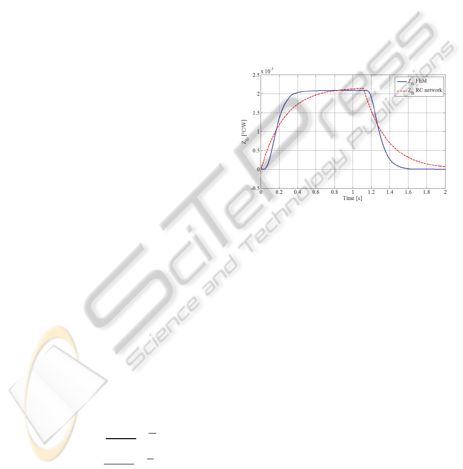
This delay is visible in Figure 5 along with the
RC network approximation of the thermal
impedance curve. As it can be observed, the
approximation is not satisfactory. At the current
stage of our research, we are exploring new circuit
topologies for better approximation. The preliminary
results indicate that such models can be obtained in
the realm of passive circuits.
Figure 5: Thermal mutual impedance calculated from a 3D
numerical simulation of a power module prototype (blue)
and its fitting (red) by means of relation (8).
It is important to underline that the use of the
FEM tool is only finalized to get the thermal
impedances curves, so it will be used only once.
The aim of this research is to investigate
alternative forms for fitting the thermal mutual
impedances.
Then the thermal behaviour of the whole module
will be characterized by the lumped parameter
model.
6 EXPECTED OUTCOME
The aim of this work is to design an automatic
procedure allowing a fast modelling of the whole
module thermal behaviour.
Specifically the choice of the lumped parameter
approach has many advantages. First of all, a circuit
is more versatile than a 3D model that needs of
specific tools to be simulated. Secondly, the
computational cost required for a lumped parameter
model is much lower than a distributed parameter
one.
ICINCO2013-DoctoralConsortium
6

The thermal behaviour of power modules can
change significantly depending on the density of
chips, the used materials and the module geometry.
Starting from the thermal impedance curves,
obtained by 3-D numerical simulation or by
experimental measurements, the methodology will
allow to find a suitable circuital network topology
able to reproduce both the single chip behaviour and
the thermal coupling between different chips.
In summary the main expected outcomes are
two. The first one is the definition of a methodology
to design lumped parameter models reproducing the
thermal behaviour of high power modules.
The second expected outcome is the availability
of particularly simply models for fast simulation of
thermal behaviour of high power modules.
REFERENCES
Y. B. Wu, G. Y. Liu, N. H. Xu and Z. C. Dou, “Thermal
Resistance Analysis and Simulation of IGBT Module
with High Power Density”, Applied Mechanics and
materials Vols 303-306, pp 1902-1907, 2013.
I. Swan, A. Bryant, P. A. Mawby, T. Ueta, T. Nishijima,
and K. Hamada, “A Fast Loss and Temperature
Simulation Method for Power Converters, Part II: 3-D
Thermal Model of Power Module”, IEEE
Transactions on power electronics, vol. 27, no. 1,
January 2012
I. R. Swan, A. T. Bryant, and P. A. Mawby, “Fast 3D
thermal simulation of power module packaging”, Int.
J. Numer. Model., vol 25, pp 378–399, July 2012.
S. Dutta, B. Parkhideh, S. Bhattacharya, G. K.
Moghaddam, R. Gould “Development of a Predictive
Observer Thermal Model for Power Semiconductor
Devices for Overload Monitoring in High Power High
Frequency Converters”, Applied Power Electronics
Conference and Exposition (APEC), pp 2305-2310,
February 2012
U. Drofenik, D. Cottet, A. Musing, J-M. Meyer and J. W.
Kolar, “Computationally Efficent Integration of
Complex Thermal Multi-Chip Power Module Models
into Circuit Simulators”, Power Conversion
Conference, Nagoya, 2007.
Z. Khatir, S. Carubelli and F. Lecoq, “Real-Time
Computation of Thermal Constraints in Multichip
Power Electronics Devices”, IEEE Transaction on
components and packaging technologies, Vol. 27, No.
2, June 2004.
S. Carubelli, Z. Khatir, “Experimental validation of a
thermal modelling method dedicated to multichip
power modules in operating conditions”,
Microelectronics Journal 34, pp.1143–1151, 2003.
R. W. Lewis, K. Morgan, H. R. Thomas and K. N.
Seetharamu, The Finite Element Method in Heat
Transfer Analysis. New York: Wiley, 1996.
C. S. Yun, P. Regli, J. WaldMeyer, and W. Fichtner,
“Static and dynamic thermal characteristics of IGBT
power modules”, In Proc. 11th Int. Symp. Power
Semiconductor Devices & ICs, pp. 37-40, May 1999.
Z. Khatir, S. Lefebvre, “Thermal Analysis of Power
Cycling Effects on High Power IGBT Modules by the
Boundary Element Method”, Semiconductor Thermal
Measurement and Management, Seventeeth Annual
IEEE Symposius, 2001.
F. Profumo, A. Tenconi, S. Facelli, B. Passerini,
“Implementation and Validation of a New Thermal
Model for Analysis, Design, and Characterization of
Multichip Power electronics Devices”, IEEE
Transaction on industry applications, vol. 35, no. 3,
May/June 1999.
N. Y. A. Shammas, M. P. Rodriguez, F. Masana, “A
simple method for evaluating the transient thermal
response of semiconductor devices”, Microelectronics
Reliability 42, pp. 109-117, 2002.
Y. A. Cengel, Heat Transfer: A practical Approach,
Mcgraw-Hill, 2nd edition, 2002.
Infineon Ltd, Thermal equivalent circuit models,
Application Note, v1.0, 2008 published at
http://www.infineon.com.
ABB Ltd, Thermal Design and Temperature Ratings of
IGBT Modules, application note published at
http://www.abb.com/semiconductors.
OntheInvestigationofLumpedParameterModelsforThermalCharacterizationofHighPowerModules
7
