
Advanced Control Concepts Suitable for Energy Efficient Hydraulic
Systems
Tadej Ta
ˇ
sner
1,2
, Vito Ti
ˇ
c
1
and Darko Lovrec
2
1
HAWE Hidravlika d.o.o., Petrov
ˇ
ce, Slovenia
2
Faculty of Mechanical Engineering, University of Maribor, Maribor, Slovenia
Keywords:
Hydraulics, Simulation, Control, Asynchronous Motor, Variable-frequency Drive Controller, Constant Pump,
Variable Displacement Pump, Hydraulic Tubing.
Abstract:
Today there are ever-increasing demands for more efficient hydraulic drive technology in terms of reducing
energy consumption, increasing reliability plus robustness, and for minimising the maintenance interventions
on the drive. In addition, the requirements and directives on the reduction of the noise, and development
tendencies in the direction of environmentally user-friendly drives, are leading to an ever-increasing usage of
the electro-hydraulic drive technology. There are two main concepts for converting electrical into hydraulic
energy: constant speed motor coupled with variable displacement pump and variable speed motor coupled with
constant pump. This article presents completed PhD tasks including modelling and simulation of both of the
two concepts along with a new concept of variable speed motor coupled with constant pump. All the concepts
are compared in dynamics and efficiency based on the simulation results. The expected results of the PhD are
a newly-synthesized SIMO controller for ’bi-variable’ control, that will be able to control hydraulic systems
in order to operate within the areas of maximum efficiency, highest dynamics or a compromise between these
two. A further contribution to the hydraulic system developers’ community will be an experimentally proven
mathematical model for the simulations of different hydraulic drive concepts. Such a model may be used for
optimising the energy-efficiencies of existing and new hydraulic machinery, as well as efficiency prediction
when building new hydraulic systems. Moreover it may also be used for determining the most suitable drive
concept for a hydraulic system with a predefined operating cycle.
1 RESEARCH PROBLEM
Today there are ever-increasing demands for more ef-
ficient hydraulic drive technology in terms of reduc-
ing energy consumption, increasing reliability plus
robustness, and for minimising the maintenance in-
terventions on the drive. In addition, the requirements
and directives on the reduction of the noise, and devel-
opment tendencies in the direction of environmentally
user-friendly drives, are leading to an ever-increasing
usage of the electro-hydraulic drive technology. This
has come to light especially in areas where higher
energy density is required, for example, on modern
milling and forming machines as well as in the seg-
ment of machinery and equipment that operates con-
tinuously, autonomously, at remote sites and without
the presence or supervision of the maintenance staff.
Such applications include:
• highly loaded machining centres
• wind-farms (especially those installed in such as
waterside bay areas)
• mobile machines (excavators, cranes, etc.)
Hydraulics are mainly used in systems where big
forces and power are required for normal operations.
High-power requirements reflects in high-energy con-
sumption. Even the slightest (at the percentage level)
optimisations regarding the energy efficiency of such
machines could result in significant savings over long
operating periods. Therefore, improved efficiency
and reduced energy consumption are two of the main
goals during modern electrohydraulic drive systems
designing.
2 STATE OF THE ART
Most of the efficiency increases could be achieved
3
Tašner T., Ti
ˇ
c V. and Lovrec D. (2013).
Advanced Control Concepts Suitable for Energy Efficient Hydraulic Systems.
In Doctoral Consortium, pages 3-11
DOI: 10.5220/0004637000030011
Copyright
c
SciTePress
during the electrical to hydraulic energy conversion
stage. In general hydraulic energy can be controlled
in two main ways:
• the throttling principle
by throttling on the directional valve
• the volumetric principle
by adjusting the pump displacement volume
The throttling principle displays good dynamic be-
haviour, but its energy losses are substantial. The
volumetric principle is more energy-friendlier but has
even worse dynamic response (Majumdar, 2000). The
volumetric principle is mostly used due to its better
efficiency.
There are two more commonly used drive con-
cepts for the volumetric adjustment of hydraulic en-
ergy:
• the direct concept
by adjusting the displacement of a variable
displacement pump
• the indirect concept
by adjusting the rotational speed of a con-
stant displacement pump
Most machines within the field of hydraulic drive
technology are still using the classic drive con-
cept—variable displacement pump driven at constant
speeds. Desiring greater robustness and lowering the
price of hydraulic drives over recent years, as well as
lower prices for variable-frequency drive controllers,
has led to the more and more popularity for using
speed-controlled constant pumps. However, such a
concept can not meet the dynamic requirements of
the classic drive concept (Lovrec and Ulaga, 2007;
Lovrec et al., 2005). Therefore the question arises as
to ’Which drive concept would be more efficient for a
particular hydraulic application?’.
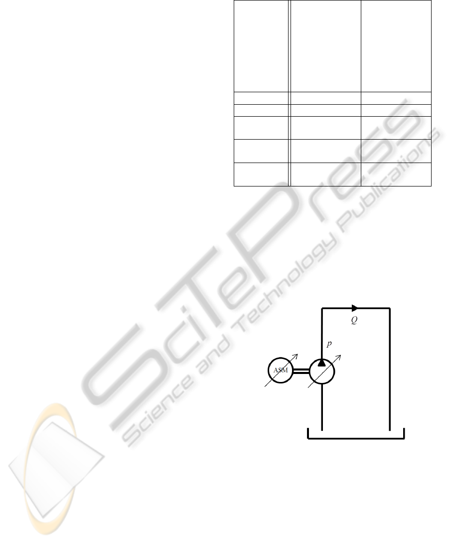
Table 1 shows a comparison between both drive
concepts: variable pump and constant motor (C1),
as well as constant pump and variable speed drive
(C2). C2 has asserted itself mainly due to good effi-
ciency and a wide operating range (Xu et al., 2010). It
also excels at lower operating costs and consecutively
smaller affects on the environment. Lower operating
costs and higher efficiency have come mainly from
a more efficient connection of the motor to the elec-
trical grid—via a variable-frequency drive controller
(Ferreira et al., 2011). However, C2 also has one ma-
jor drawback a slow system response that occurs due
to rotating parts’ moment of inertia (motor rotor and
rotary parts of the pump). The response of C1 is up to
5 times faster than the response of C2 (Lovrec et al.,
2005), but both responses are good enough for the
most hydraulic applications (Lovrec et al., 2009).
Table 1: Comparisons between both the more-commonly
used hydraulic drive concepts.
Concept 1
(C1):
Concept 2
(C2):
Frequency
Inverter
Asynchronous
Motor
Asynchronous
Motor
Variable Axial
Piston Pump
Constant Gear
Pump
efficiency lower higher
reliability high high
operating
costs
higher lower
system
dynamics
higher
4.4
lower
1
purchase
price
higher lower
If both concepts (C1 and C2) were to be com-
bined, then we would obtain increased dynamics due
to the variable displacement pump (Song et al., 2008)
and increased efficiency due to the variable-frequency
drive controller (Ferreira et al., 2011). Such a com-
bined drive concept (Figure 1), as well as the effect of
different motor speeds and different pump displace-
ments on the efficiency and dynamics of the system,
yet this is rarely mentioned in literature.
Figure 1: Combined drive concept (C3) - variable speed
asynchronous motor coupled with a variable displacement
pump.
3 OUTLINE OF THE
OBJECTIVES
Based on the experience gained during the initial
study of the dynamic behaviour and implementation
of appropriate control strategies of both drive con-
cepts, this new drive concept (a combination of vari-
able speed drive and variable displacement hydraulic
SIMULTECH2013-DoctoralConsortium
4

pump) needs to be explored in more detail. In order
to achieve this objective both existing concepts will
have to be studied on the basis of simulation and ex-
perimental analysis. The presented study will focus
on both the selection and implementation of an ap-
propriate control concept for this new drive concept,
as well as the comparisons between the efficiencies
for all three drive concepts.
The results obtained on the basis of these stud-
ies will be transferred to the proposed drive concept.
Firstly, a new solution for the control concept will
have to be found, because multiple physical quantities
have to be monitored and changed at the same time:
• swashplate angle of the variable axial piston pump
• rotational speed of the motor
As both quantities directly effect oil pressure within
the hydraulic circuit, an appropriate control strategy
for such Single Input Multiple Output (SIMO) sys-
tem will have to be synthesised. Such a control strat-
egy then raises some further questions. Which quan-
tity should be changed and how much, in order to
maximise the efficiency and/or dynamics of the drive?
What are the efficiency benefits of the new drive con-
cept for the particular operating cycles of different
machines?
4 METHODOLOGY
These research activities have an interdisciplinary na-
ture, since they combine the knowledge of technical
apparatus (specifications, principle of operations and
performances of the individual components) as well
as classic and modern methods for controlling sys-
tems. The starting point of scientific activities is a
good knowledge of the individual components, their
specific structures and modes of operation that is ob-
tained from the manufacturer or provider of com-
ponents. All of those properties are needed when
constructing a mathematical model for simulating all
three drive concepts. It is necessary to evaluate all
the existing drive concepts and compare them using
simulation as well as experimentally.
Appropriate and powerful simulation tools need
to be used for simulation. The existing test site and
equipment to be used for experimental verification of
the simulation results will have to be redesigned and
updated in terms of performance, flexibility and ver-
satility. A new system for controlling and monitoring
the test site will have to be designed that includes au-
tomatic set-point and disturbance generation, as well
as data acquisition and archiving.
5 EXPECTED OUTCOME
The expected outcome of this research is to make
some original contributions to the development of this
scientific discipline. The first scientific contribution
of the PhD work is a mathematical model for evalu-
ation of the dynamics and efficiency of different hy-
draulic drive concepts that can be verified on a test-
site. A further contribution is the design of an appro-
priate control strategy for ’bi-variable’ (variable dis-
placement, variable speed) hydraulic drive units that
will be based on modern control and decision-making
concepts.
6 STAGE OF THE RESEARCH
Most of the theoretical part of the work has been al-
ready done, meaning that the simulation model al-
ready consists of the following mathematical models:
• variable-frequency drive controller,
• asynchronous motor,
• variable displacement axial piston pump,
• fixed displacement internal gear pump,
• and hydraulic tubing
All the simulations regarding the efficiencies of dif-
ferent drive concepts have been run. Some results
have already been experimentally verified on a test-
site.
Therefore the used simulation model, including
the simulation results, are presented in this article.
7 SIMULATION MODEL
The simulation model of C1 consists of an asyn-
chronous motor directly connected to grid, a vari-
able displacement axial piston pump, and hydraulic
tubing. The simulation model of C2 consists of
a variable-frequency drive controller with an asyn-
chronous motor connected to it, a fixed displacement
internal gear pump, and hydraulic tubing. The simu-
lation model of C3 consists of a variable-frequency
drive controller with an asynchronous motor con-
nected to it, a variable displacement axial piston
pump, and hydraulic tubing.
The asynchronous motor is coupled to the pump
that pumps the hydraulic fluid from a hydraulic tank
through a long length of hydraulic tubing, and back
to the tank. The flow through the tubing causes a
pressure drop that is measured directly after the pump
using a pressure sensor. The following subsection
AdvancedControlConceptsSuitableforEnergyEfficientHydraulicSystems
5
presents the models of all the components used in
simulation.
7.1 Asynchronous Motor Model
The more simplified model of the three-phase asyn-
chronous motor consists of two pairs of magnetically-
coupled symmetrical three-phase windings. Both of
the three-phase windings (stator winding and rotor
winding) are identical. The same model also ap-
plies for a squirrel-cage rotor, where currents start
flowing due to electro-magnetic induction. The more
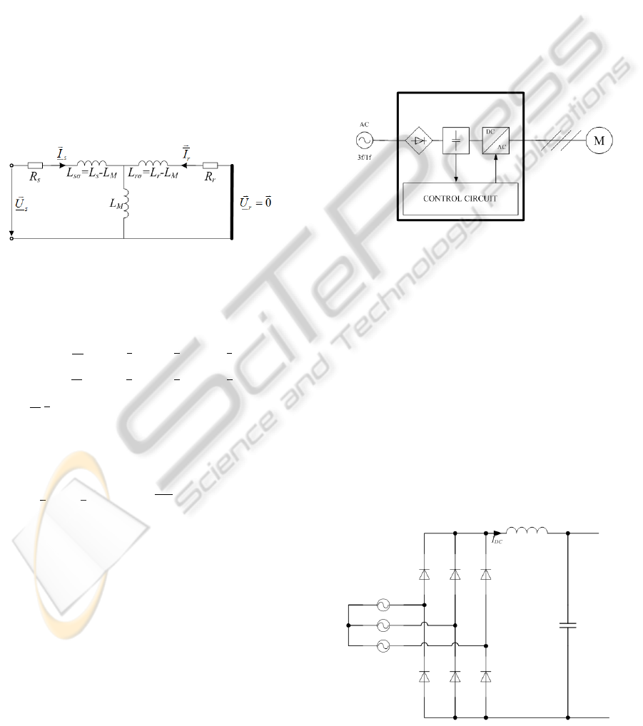
commonly used model for the dynamic simulation of
asynchronous motors is based on the so-called ’T’
equivalent circuit (Figure 2). Such a model is used for
static and dynamic simulations, although it neglects
core losses (saturation and eddy current losses). (Diaz
et al., 2009) The following equations can be obtained
Figure 2: Electrical representation of the ’T’ equivalent cir-
cuit of an asynchronous motor.
from the ’T’ equivalent circuit for a squirrel-cage ro-
tor:
~
U
s
= R
s
·
~
I
s
+ L
s
·
˙
~
I
s
+ L
M
·
˙
~
I
r
~
0 =
~
U
r
= R
r
·
~
I
r
+ L
r
·
˙
~
I
r
+ L
M
·
˙
~
I
s
(1)
where
~
U/
~
I are vectors of voltage/current phasors for
each phase, R winding resistances and L inductances,
where subscript ’r’ denotes rotor, ’s’ stator and ’M’
mutual. The electromechanical torque can be written
as:
˙
~
I
T
s
L
M
·
˙
~
I
r
= T
em
= J
dΩ
dt
+ b · Ω + T
L
(2)
where Ω is the mechanical rotational frequency of the
rotor, b the viscous friction coefficient and T
L
the load
torque. (Delaleau et al., 2001)
All the necessary parameters of the asynchronous
motor needed for the simulation model were calcu-
lated from the measurements’ results from the locked
rotor and no-load tests.
7.2 Variable-frequency Drive
Controller Model
The variable-frequency drive controller is a device
that can change the rotational frequency or torque
of an electric motor by modifying the frequency and
amplitude of the motor’s supply voltage. A typical
variable-frequency drive controller consists of (Fig-
ure 3):
• a rectifier,
rectifies input AC voltage
• DC link,
energy storage
• an inverter,
converts DC to AC
• and a control circuit.
measures motor currents and controls the in-
verter
Figure 3: Block diagram of a variable-frequency drive con-
troller.
7.2.1 Rectifier Model
The more commonly used rectifier type in variable-
frequency drive controllers is a full-wave rectifier
with an LC filter. Such a rectifier consist of three pairs
of rectifier diodes and a filter inductor, which charge
the DC link capacitor. Electrical circuit of such rec-
tifier is shown in Figure 4. Assuming that the LC fil-
ter is ideal and that the voltage drop on the diodes is
constant, the rectifier losses can be expressed as (3),
where U
F
is the diode forward voltage. The factor 2
in the equation represents current flows through one
lower and one upper diode.
P
RECT
= 2 · I
DC
·U
F
(3)
Figure 4: Three phase full wave rectifier with LC filter.
SIMULTECH2013-DoctoralConsortium
6
7.2.2 DC Link Model
An ideal DC link capacitor is used in our variable-
frequency drive controller.
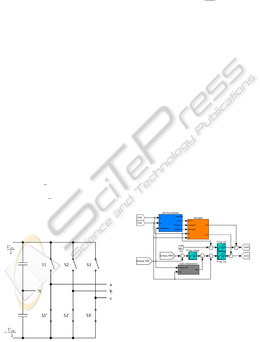
7.2.3 Inverter Model
Most of the inverters are controlled based on the
principle of space vector modulation. A three-phase
vector Pulse Width Modulation (PWM) inverter re-
quires three transistor bridges. Each bridge consists
of two transistors operating in the switching region.
Such an inverter can drive any three-phase load, with
or without the neutral line. Figure 5 shows such
an inverter, where the transistors are represented as
switches. The transistors used in the inverters are
either Isolated Gate Bipolar Transistors (IGBTs) or
Metal Oxide Semiconductior Field Effect Transistors
(MOSFETs) and are controlled by a microcontroller.
A simplified loss model for switching and conductive
losses of MOSFETs will be used (Shen et al., 2006),
because our inverter uses MOSFETs. The energy loss
in one switch of both transistors within a transistor
bridge, can be expressed as (4). Where all the data
are characteristics of the MOSFET except U and I, are
dependent on the inverter load, and represent the volt-
age on the MOSFET and the current flowing through
the MOSFET, respectively.
W
SW
=
1
2
I
D
U
D
(t
ON
+t
OFF
)
+
1
2
(C
GD
+C
DS
)U
2
D
(4)
The conducting losses for the transistors during their
on time are (4)
P
ON
= R
DS(on)
·
i
2
a
+ i
2
b
+ i
2
c
(5)
Figure 5: Three phase bridge inverter.
and the total losses are (6)
P
INV
= P
ON
+
W
SW
f
SW
(6)
where f
SW
is the inverter switching frequency.
7.2.4 Control Circuit Model
Most variable-frequency drive controllers control the
drives using the Sensorless Vector Control (SVC)
principle. SVC needs an inverse dynamic model of
the asynchronous motor in dq coordinates for it to
function. Synthesis of such a model is beyond the
scope of this article. The basic parts of its synthesis
are presented in (Stekl, 2007). A simplified block di-
agram of the control circuit is shown in Figure 6, its
main blocks are:
• rotor flux estimator,
rotor flux is needed for decoupling
• decoupling,
decouples d and q voltage components so
each can be changed without effecting the other
• two current controllers,
control magnetising (d) and torque (q) cur-
rent components by changing their voltages
• speed controller,
controls motor rotational speed by changing
the torque current component
• and load compensation.
detects the load and increases the required
torque current accordingly, in order to maintain
the desired rotational speed
Figure 6: Control circuit block diagram.
7.3 Hydraulic Pump Models
Gear and an axial piston pump were used for the
conversion of mechanical energy into hydraulic en-
ergy. Gear pumps have constant displacement vol-
ume, whereas axial piston pumps may also be ad-
justable. The flow through them can be changed by
adjusting the swash-plate angle.
AdvancedControlConceptsSuitableforEnergyEfficientHydraulicSystems
7
Wilson (Wilson, 1949) started modelling hy-
draulic pumps at the end of the first half of the 20th
century. He designed a static model that takes into ac-
count volumetric and frictional losses of pumps. His
model was later improved by some authors, their work
was summed-up by Rydberg (Rydberg, 2009). How-
ever, these models are only useful for the already-
made and tested pumps, because their coefficients
are obtained from measurements and experiments on
the stations. (Jeong and Kim, 2007) Our models are
based on Wilson’s model and use certain modifica-
tions mentioned by Rydberg.
7.3.1 Fixed Displacement Internal Gear Pump
Model
The flow Q of the hydraulic fluid through the gear
pump is the proportional to the rotational speed n
of the pump. Both quantities are connected by the
pump’s displacement V
g
, which is a characteristic
property of each pump. At higher pressures the
pump’s flow slowly starts to drop, due to the com-
pressibility of the fluid and the greater leakage losses.
These losses are covered under the concept of the vol-
umetric efficiency of the pumps, which depends on
the pressure difference ∆p that the pump must create.
Such losses can easily be presented as a parallel hy-
draulic resistance R
p
of the ideal pump (an analogy
with Norton’s theorem in electrical engineering). (7)
Q = n ·V
g
−
∆p
R
p
(7)
The pump’s operating torque is proportional to the
pressure difference that the pump creates, due to the
law of energy conservation. The torque T must, in ad-
dition to creating pressure difference, overcome those
losses that occur due to lubrication of the pump and
friction between the moving parts of the pump b. (8)
T = ∆p ·V
g
+ n · b (8)
7.3.2 Variable Displacement Axial Pump Model
Similarly as for the constant gear pump, an equation
can also be written for the variable displacement axial
piston pump. The flow of the pump is affected by the
pump’s displacement setting α, therefore we obtain
(9) from (7).
Q = n · α ·V
g
−
∆p
R
p
(9)
The pump’s displacement setting has a similar ef-
fect on the required operating torque. The losses ap-
pear due to the lubrication and friction of the rotating
parts b, but additional losses of the friction between
piston and walls C must also be taken into account.
(10)
T = ∆p · α ·V
g
+ ω · α · b + ω ·
tanα
tanα
max
·C (10)
7.4 Hydraulic Tubing Model
The dynamic behaviour of the fluid within the
pipeline can be modelled in several different ways.
The most exact model is based on the Navier-Stokes
equations and the law of mass conservation, which re-
sults in a system of partial differential equations that
are too much time consuming for such simulations.
Such an exact model of a hydraulic pipeline was
unnecessary, therefore a more appropriate—discrete
model was chosen, also known as a model with con-
centrated parameters. The discrete model is simi-
lar to electrical circuits used by electrical engineers,
where the properties of a circuit are represented by
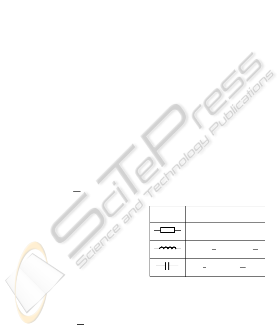
resistance, capacitance and inductance. In hydraulics
the properties of a pipeline system are hydraulic re-
sistance R
H
(pressure drop in a tube due to flow),
hydraulic capacitance C
H
(pressure drop in a tube
due to tube volume increase/decrease) and hydraulic
inductance L
H
(pressure drop due to fluid accelera-
tion/deceleration). The analogy between electronics
and hydraulics is presented in Table 2.(Ta
ˇ
sner and
Lovrec, 2011)
Table 2: Electrical-hydraulic analogy.
Electrical
Symbol
Electrical
Equation
Hydraulic
Equation
U = R · I p = R
H
· Q
p = L ·
dI
dt
p = L
H
·
dQ
dt
U =
1
C
R
Idt
p =
1
C
H
R
Qdt
The hydraulic pipeline system split into n seg-
ments can be represented using the electrical symbols
as shown in Figure 7. Each segment represents part
of a pipeline with a length of l/n, where l is the total
length of the pipeline. The number of segments also
equals the number of possible pressure measurement
points (For example, if the tube is modelled as one
segment, the pressure in the middle of the tube cannot
be calculated.)
The transfer function of such a segment can be ex-
pressed as a second-order ordinary differential equa-
SIMULTECH2013-DoctoralConsortium
8
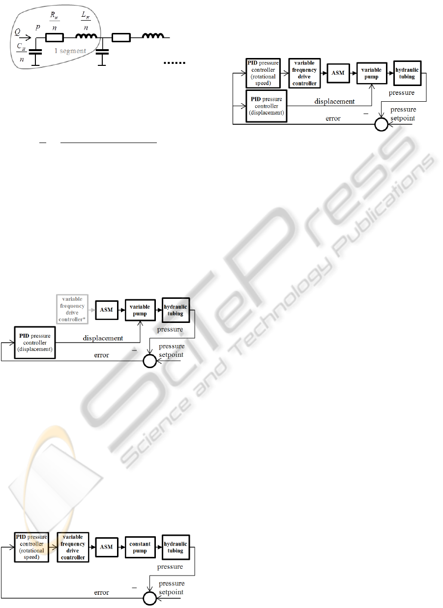
Figure 7: Hydraulic tubing represented using electrical
symbols.
tion within the Laplace frequency domain (11).
p
Q
=
L
H
· s + R
H
C
H
L
H
· s
2
+C
H
R
H
· s + 1
(11)
8 SIMULATION RESULTS
Simulations were performed on different combina-
tions of simulation models, as described in the previ-
ous section, using MATLAB/Simulink software. The
same hydraulic tubing was used as a load when simu-
lating all three concepts. Pressure control was realised
using a PID controller using a clamping anti-windup
method for the integral part.
Figure 8: Control block diagram of C1 and C1*.
• In C1 the pressure is controlled by changing the
axial piston pump’s displacement, as shown in
Figure 8. The asynchronous motor (ASM) was
connected directly to power-grid (C1), and via the
variable frequency drive controller, set to a con-
stant rotational speed of 1500 min
−1
(C1*). C1*
was just added to include the variable-frequency
drive controller’s losses to C1.
• In C2 the pressure is controlled by changing mo-
tor’s rotational speed that drives the constant gear
pump, as shown in Figure 9.
Figure 9: Control block diagram of C2.
• In C3 the pressure is controlled by two parallel
PID controllers that change the motor’s rotational
speed and the axial piston pump’s displacement,
as shown in Figure 10.
Figure 10: Control strategy of C3.
The pressure set-point was changed according to
a combined cycle (sine, ramp and step). The pres-
sure responses of the different drive concepts were ob-
served and compared according to dynamics and ef-
ficiency. The simulation results are presented in Fig-
ures 11- 12, and in Table 3. The upper part of the Ta-
ble 3 shows the efficiency comparisons. The average
efficiency is calculated as a quotient of the produced
hydraulic energy and the required electrical energy.
A first look at the efficiencies reveals that C1 had the
highest efficiency, due to the fact that a variable fre-
quency drive controller was not used in C1. The new
combined concept (C3) was the most efficient from
amongst all the concepts that use variable-frequency
drive controllers. If we had wanted to compare oper-
ating cycle costs, apparent power would have to have
been compared, as companies pay for both the real
power [W] and the reactive power [VAr]. For most
of the new variable-frequency drive controllers, real
power is almost equal to apparent power, due to built-
in power-factor corrections (their cosφ ≈ 1, as reac-
tive power flows only between the motor and the con-
troller).
The bottom part of the Table 3 compares all the
concepts according to control performances. Settling-
times in response to step from 50-150 bar were calcu-
lated - a close-up of the step responses is shown in
Figure 12. Settiling-time is the time when the pres-
sure within the pipeline settled within 1 % of the pres-
sure set-point. Moreover, the Root Mean Square Er-
ror (RMSE) was calculated for the whole cycle and
for the tracking part (ramp and sine). It can be seen
that the C1 had the best dynamics and lowest overall
RMSE. C2 had the worst RMSE as well as the lowest
dynamics with settling-time 6 times slower than C1.
This was mostly due to the moment of inertia of the
motor rotor and the rotating parts of the pump, as the
motor must accelerate and decelerate according to the
pressure set-point changes. Although C1 had the best
dynamics, C3 tracked the pressure set-point more ac-
curately.
AdvancedControlConceptsSuitableforEnergyEfficientHydraulicSystems
9
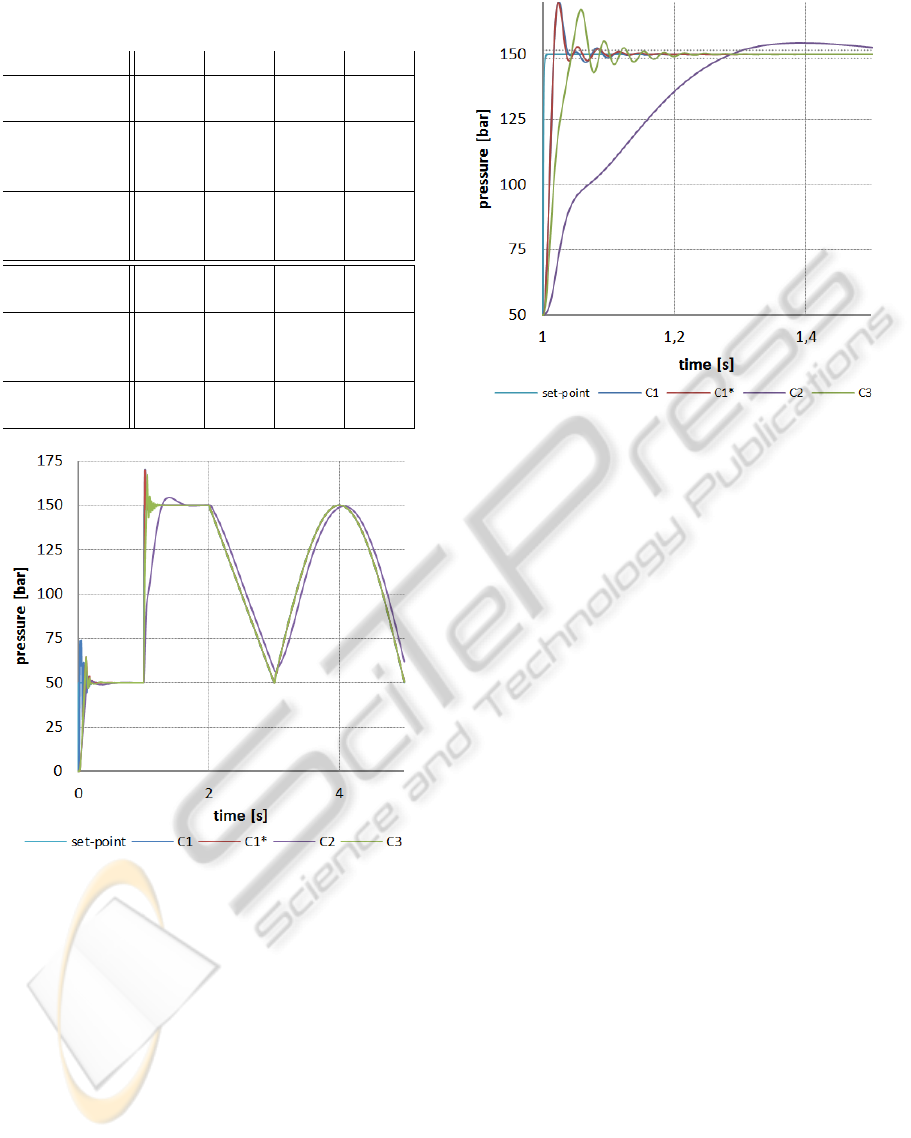
Table 3: A comparison between different drive concepts’
simulation results.
C1 C1* C2 C3
average
efficiency
72 % 60 % 65 % 67 %
energy
required
[kJ]
31.6 33.8 30.9 32.2
energy
produced
[kJ]
22.7 20.1 20.2 21.7
RMSE
[bar]
4.92 6.40 12.9 7.16
tracking
RMSE
[bar]
0.231 0.227 5.95 0.178
settling
time [ms]
92 95 570 176
Figure 11: Responses of the different drive concepts to the
combined cycle.
9 CONCLUSIONS
The simulation results showed that all three concepts
are useful in the field of hydraulic drives. Although
C2 had relatively slow dynamics, it can be used for
processes where high dynamics is not critical. While
C1 is the oldest concept, it still has the best efficiency
- but we must also consider the reactive power of the
asynchronous motor when it is powered directly from
the grid. The newly-proposed concept (C3) had a very
good tracking performance of slower changes of the
pressure set-point, moreover it also had the best effi-
ciency of all the variable-frequency drive controlled
Figure 12: Step response close-up.
concepts. Its dynamics could be improved by imple-
menting a better controller for the ’bi-variable’ pres-
sure control. The controller could use a look-up ta-
ble for efficiencies and set the swashplate angle and
motor rotational speed to such value that maximum
efficiency is achieved.
10 FURTHER WORK
Further steps in pursuing the PhD are:
• experimental verification of efficiencies for each
modelled component on the test site,
• synthesis of a new SIMO controller for ’bi-
variable’ pressure control (max dynamics or max
efficiency control),
• tuning and testing of the new controller within a
simulation environment,
• experimental evaluation of the tuned SIMO con-
troller and
• experimental evaluation of the efficiencies of all
three concepts.
11 EXPECTED OUTCOME
The expected results of the PhD are a newly-
synthesized SIMO controller for ’bi-variable’ con-
trol, that will be able to control hydraulic systems in
order to operate within the areas of maximum effi-
ciency, highest dynamics or a compromise between
SIMULTECH2013-DoctoralConsortium
10

these two. A further contribution to the hydraulic sys-
tem developers’ community will be an experimentally
proven mathematical model for the simulations of dif-
ferent hydraulic drive concepts. Such a model may
be used for optimising the energy-efficiencies of ex-
isting and new hydraulic machinery, as well as effi-
ciency prediction when building new hydraulic sys-
tems. Moreover it may also be used for determining
the most suitable drive concept for a hydraulic system
with a predefined operating cycle.
ACKNOWLEDGEMENTS
Operation part financed by the European Union,
European Social Fund. Operation implemented in the
framework of the Operational Programme for Human
Resources Development for the Period 2007-2013,
Priority axis 1: Promoting entrepreneurship and
adaptability, Main type of activity 1.1.: Experts and
researchers for competitive enterprises.
REFERENCES
Delaleau, E., Louis, J.-P., and Ortega, R. (2001). Modelling
and control of induction motors. International Jour-
nal of Applied Mathematics and Computer Science,
11(1):105–129.
Diaz, A., Saltares, R., Rodriguez, C., Nunez, R., Ortiz-
Rivera, E., and Gonzalez-Llorente, J. (2009). Induc-
tion motor equivalent circuit for dynamic simulation.
In Electric Machines and Drives Conference, 2009.
IEMDC ’09. IEEE International, pages 858–863.
Ferreira, F. J. T. E., Fong, J., and De Almeida, A. (2011).
Ecoanalysis of variable-speed drives for flow regula-
tion in pumping systems. Industrial Electronics, IEEE
Transactions on, 58(6):2117–2125.
Jeong, H.-S. and Kim, H.-E. (2007). A novel performance
model given by the physical dimensions of hydraulic
axial piston motors: Experimental analysis. Journal of
Mechanical Science and Technology, 21(4):630–641.
Lovrec, D., Kastrevc, M., and Hribernik, D. (2005). Com-
parison of variable electrohydraulic supply systems by
example of pressure control. Ventil, 11(3):153–160.
Lovrec, D., Kastrevc, M., and Ulaga, S. (2009). Electro-
hydraulic load sensing with a speed-controlled hy-
draulic supply system on forming-machines. The In-
ternational Journal of Advanced Manufacturing Tech-
nology, 41(11-12):1066–1075.
Lovrec, D. and Ulaga, S. (2007). Pressure control in hy-
draulic systems with variable or constant pumps? Ex-
perimental Techniques, 31(2):33–41.
Majumdar, S. R. (2000). Oil Hydraulic Systems: Princi-
ples and Maintenance. McGraw-Hill Education (In-
dia) Pvt Limited.
Rydberg, K.-E. (2009). Efficiencies for variable hydraulic
pumps and motors mathematical models and opera-
tion conditions.
Shen, Z., Xiong, Y., Cheng, X., Fu, Y., and Kumar, P.
(2006). Power mosfet switching loss analysis: A new
insight. In Industry Applications Conference, 2006.
41st IAS Annual Meeting. Conference Record of the
2006 IEEE, volume 3, pages 1438–1442.
Song, X., Yao, X., Li, Z., and Wang, J. (2008). Equip-
ping variable-speed pumping source to reduce use-
less power of missile-loaded hydraulic actuator. In
Systems and Control in Aerospace and Astronautics,
2008. ISSCAA 2008. 2nd International Symposium on,
pages 1–5.
Stekl, P. (2007). 3-phase AC Induction Vector Control Drive
with Single Shunt Current Sensing.
Ta
ˇ
sner, T. and Lovrec, D. (2011). Comparison of modern
electrohydraulic systems. In 34th International Con-
ference on Production Engineering.
Wilson, E. W. (1949). Performance criteria for positive dis-
placement pumps and fluid motors. In ASME Semi-
annual Meeting, volume 71.
Xu, M., Chen, G., and Ni, J. (2010). Hierarchical control
of energy regulation based variable-speed electrohy-
draulic drive. In Information and Automation (ICIA),
2010 IEEE International Conference on, pages 2401–
2405.
AdvancedControlConceptsSuitableforEnergyEfficientHydraulicSystems
11
