
A Low Cost Platform based on FES and Muscle Synergies for Postural
Control Research and Rehabilitation
D. Galeano
1
, F. Brunetti
1,2
, D. Torricelli
2
, S. Piazza
2
and J. L. Pons
2
1
Catholic University of Asunci
´
on, Asunci
´
on, Paraguay
2
Bioengineering Group, CSIC, Arganda del Rey, Spain
Keywords:
Posturography, FES, Muscle Synergies, Kinect, Wii Fit.
Abstract:
This paper presents a low cost system for the assessment, diagnosis and training of balance based on static
posturography and functional electrical stimulation (FES). This system includes low cost technology as the
Wii Fit Balance Board and the Kinect. The posturography is a complementary tool to clinical diagnosis,
and allows to find sensory systems and inputs degraded by different pathologies. The presented system also
allows to explore new rehabilitation techniques based on functional electrical stimulation. Precisely, this paper
describes the implementation of a novel balance and posture control rehabilitation approach based on muscle
synergies.
1 INTRODUCTION
There are several diseases that can affect human bal-
ance and posture control. Such diversity requires the
participation of different specialists in the diagnosis
and treatment process like neurologists, otolaryngol-
ogists and ophthalmologists among others. Posturog-
raphy is defined as an objective assessment technique
of postural control based. In this way, the monitor-
ing of the center of pressure of the person has proven
to be an effective tool complementary to clinical di-
agnosis in order to quantify this neuromotor disorder.
This technique also can be be used as a complemen-
tary tool to help clinicians with the diagnosis of ver-
tigo.
Posturography evaluates each of the sensory sys-
tems (visual, somatosensory and vestibular) involved
in the complex balance system. Its purpose is to iso-
late the contribution of each of these systems to eval-
uate the status of each one separately. It also assesses
movement strategies for maintaining balance, exam-
ines the stability limits of the person and the ability to
control voluntary movement.
Balance control is an important functional compo-
nent of human gait. After spinal cord injury (SCI) or
stroke, balance control if one of the first rehabilitation
objectives towards the restoration of functional gait.
In this scenario, posturography also plays a key role
to evaluate the progress of the affected subject. Clas-
sic therapies of posture control rehabilitation include
exercises to improve stability limit or guided move-
ments to reinforce control efforts of patient.
Over the last years muscle synergies have been de-
scribed for several composed movements like those
exerted during normal postural control. Muscle syn-
ergies can be understood as functional muscle co-
activation patterns (D’Avella and Bizzi, 2005). This
theory proposes the existence of simplified mecha-
nisms and signals that can control several muscles at
the same time. The most interesting aspect of this
theory is the consistency of these synergies among
subjects, and its stability intra subject. The use of
this knowledge for rehabilitation is still a research
goal, as well as the assessment of muscle synergies in
functional tasks after stroke or SCI, (Torricelli et al.,
2012).
The use of Functional Electrical Stimulation
(FES) to interact with muscle synergies during the re-
habilitation of balance is a novel approach proposed
by Piazza et al., (Piazza et al., 2012). This paper
presents a low cost system that enables the imple-
mentation of this novel rehabilitation paradigm. It
is a posturography tool to help with the assessment
of postural control and its rehabilitation. The main
contribution of the work lies in its simplicity and its
potential use in rehabilitation. It is an exploratory de-
vice to study new rehabilitation approaches of balance
control while monitoring the status of human balance
and postural control system. The presented tool en-
able the evaluation the effectiveness of current treat-
21
Galeano D., Brunetti F., Torricelli D., Piazza S. and L. Pons J..
A Low Cost Platform based on FES and Muscle Synergies for Postural Control Research and Rehabilitation.
DOI: 10.5220/0004638300210031
In Proceedings of the International Congress on Neurotechnology, Electronics and Informatics (NEUROTECHNIX-2013), pages 21-31
ISBN: 978-989-8565-80-8
Copyright
c
2013 SCITEPRESS (Science and Technology Publications, Lda.)

ments and the design of new ones. The paper presents
technical details of the system and preliminary re-
sults.
Further stages of this work include the validation
of the designed posturography system comparing to
similar ones like the NedSVE/IBV
R
(Baydal et al.,
2010) of the Institute of Biomechanics of Valencia,
or the SMART Balance Master of Neurocom
R
. Af-
ter this validation, the design of new herapies based
on FES and muscle synergies will be possible and its
evaluation in clinical environment.
2 ASSESSMENT
METHODOLOGY AND
POSTURAL CONTROL
REHABILITATION
In this section, balance assessment methods used in
posturography are reviewed, as well as the tests de-
signed for this purpose and existing proposals for re-
habilitation based on synergies.
2.1 The Computerized Dynamic
Posturography (CDP)
Computerized Dynamic Posturography (CDP) was
designed and developed by Nashner. It was clinically
studied in collaboration with Black and marketed in
1986 as Equitest by Neurocom Inc., (Faraldo, 2009).
The CDP is a technique that analyzes subject’s
postural control in static standing and and his/her re-
sponse to destabilizing conditions. It is is based on
the idea that the center of gravity (COG) oscillations
reflect postural instability. Generally CDPs are based
on dynamometric platforms. These systems analyze
the postural oscillations by recording the vertical pro-
jection of gravity force, known as Center of Pressure
(COP). More frequent tests made with similar plat-
forms are:
• Sensory System or Romberg’s Test. It is aimed
at determining the ability of the patient to inte-
grate the three systems responsible for assessing
standing balance and body sway while different
sensory conditions are applied. The results of
this test are compared with results of normal sub-
jects. It is performed with eyes open and eyes
closed, with and without foam on which the sub-
ject stands. It can also be performed with the
patient’s head retroflexed, causing distortion in
neck proprioceptors. These tests can also be used
to evaluate proprioceptive information by making
patients to rely in vestibular information to main-
tain the balance, (Khasnis and Gokula, 2003).
• Stability Limit Test. It assess the capacity of the
subject to bring his COP to the border of his/her
stability limit. Basically, this test is used to as-
sess the maximum distance the patient can move
his/her COP without changing the base of sup-
port, i.e. without moving his/her feet. During the
test, the subject can see his/her COP representa-
tion on a computer screen in front of him, and
he/she should move it toward the stability limits
without moving its base of support. The test in-
cludes up to eight sequential different targets lo-
cated around theoretical stability limits (according
to previous measurements with healthy subjects).
• Rhythmic and Directional Tests. These tests
try to assess subject’s ability to perform rhythmic
movements around of its center of gravity (COG).
The subject isa asked to follow with his/her COP
moving targets whose speed and range are config-
urable. The target is moved to a percentage of the
stability limit previously calculated for the sub-
ject. This test is usually performed in the antero-
posterior and mediolateral directions.
2.2 Hybrid Approaches in Assisted
Neuromotor Rehabilitation
Hybrid exoskeletons have emerged as a way to im-
prove motor assistance using the benefits of FES and
robotic exoskeletons. They overcome individual lim-
itations of the methods used separately. The FES uses
natural muscles as actuators to generate a movement,
which provides benefits not only functional but physi-
ological. Robotic exoskeletons artificial actuators are
used to move the members that can not be fully or
partially controlled voluntarily.
Generally, people affected by stroke and SCI have
healthy muscles. The hybrid approach proposes the
use of their own muscles to complement the action
of the robotic exoskeleton. Muscles are activated co-
ordinately with the exoskeleton controller by means
of an electrical stimulation system, (Del-Ama et al.,
2012). This approach results in a eduction of energy
demand and allows the exoskeleton to use lighter and
less powerful actuators. Moreover, this solution is
considered more natural and help to preserve existing
biological structures. Main problem when using FES
is that it can produce muscle fatigue after long peri-
ods of stimulation. This problem limits the time of
use. This is not a problem when using exoskeletons,
which can be used for a longer time.
Balance control is an important not only when re-
habilitating after stroke or SCI but also when using
NEUROTECHNIX2013-InternationalCongressonNeurotechnology,ElectronicsandInformatics
22

exoskeletons. Hyper is a spanish research project
aimed at developing new neurorobotics and neuro-
prosthetics therapies for people affected by stroke or
SCI. First clinical interventions include the rehabili-
tation of balance and postural control. The use use of
hybrid approaches is well considered by clinicians but
they way they are used in this rehabilitation process
and it effectiveness is not clear yet for the scientific
community.
The control of the assistive device is also not clear
in terms of compensation actions and movement rou-
tines. The most most common approach over the last
years, was the so called “assist-as-needed” (AAN)
paradigm, (Cai et al., 2006). Following this paradigm,
the interaction between the assistive device and the
natural involved mechanisms in the considered task is
given in terms of the final results, and not consider-
ing the underlying status of biological control mech-
anisms. In this way, Hyper encourages the study and
development of new therapies to support classic ones.
These novel treatments are mainly driven by bioin-
spired mechanisms for better and deeper interaction
between the assistive device and remaining neuromo-
tor control structures, in order to reinforce and reha-
bilitate them in a more natural way.
2.3 Muscle Synergies
The study of human control system is a open research
field where there are still many questions to answer.
One of them is how is coded the information to con-
trol the large number of degrees of freedom of human
movements. More specifically, this problem states
that to generate a specific motor task, there are multi-
ple combinations of muscle activations that can gen-
erate similar results. Muscle synergies theory is a
proposed answer to this question. The central ner-
vous system can solve the complex task by choosing
a specific set of muscle activations through a combi-
nation of a small set of neural patterns, called synergy,
(D’Avella and Bizzi, 2005).
Each muscle receives as input a modulating signal
from higher neural centers, and outputs a weighted
activation signal to activate a set of muscles. The ac-
tivation of each muscle can be seen is a weighted sum
of all synergies commands connected to it, (Torricelli
et al., 2011). Then, muscle synergies can translate
small sets of variables coming from the central ner-
vous system into higher dimensional signals. They
are strictly correlated to the functional performance
and their modulation are related with user workspace.
The most interesting characteristic of muscle syner-
gies is that they are consistent inter healthy subjects,
(D’Avella and Bizzi, 2005)(Piazza et al., 2012).
Mathematically, as indicated in (Torricelli et al.,
2011), can be expressed by the following equation
that describes the activation of a single muscle m:
m(t) =
K
∑
i
c
i
(t)w
i
(1)
in which
• m is the activation of the muscle function of time.
• c is the neutral command i-th synergy function of
time.
• w is the constant weight of the i-th synergy to the
muscle in question.
• K is the number of synergies.
The use muscle synergies knowledge to rehabili-
tate postural control is not clear. However, their role
in functional movements and their importance have
being already reported (D’Avella et al., 2006) (Piazza,
2013). This encourage Hyper scientific team to take
them into account to favour the development of more
efficient rehabilitation therapies by closely interacting
with involved muscle synergies in balance control. In
this way, FES can be used to develop and interact with
synergies and muscle activation patterns.
3 PROPOSED SYSTEM
In this section we describe the low-cost platform de-
veloped to perform static posturography tests and sup-
port treatments based of FES and muscle synergies.
Balance control assessment platforms are usually not
open and they are commercially available only as a
posturography tool. Thus, a novel low cost and open
posturography platform was developed. The main ob-
jective of this platform is to support the development
of novel balance control rehabilitation therapies in the
framework of Hyper project.
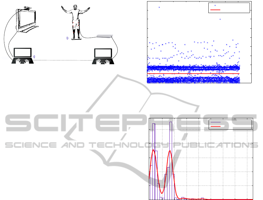
Figure 1 shows the outline of the developed plat-
form which is further described. The platform is
based on a distributed architecture, which include sev-
eral components: the posturography controller, the
real-time neuroprosthetic controller, a Wii Fit Balance
Board, a Kinect camera and the TEREFES electros-
timulation system, (Brunetti et al., 2011).
3.1 Wii Fit Balance Board
Wii Fit balance board is an input device included in
the Wii Fit from Nintendo
R
. It is a wireless device
that uses Bluetooth technology to communicate with
the Wii console. It is equipped with four resistive
pressure sensors located in each corner of the table.
ALowCostPlatformbasedonFESandMuscleSynergiesforPosturalControlResearchandRehabilitation
23
Wii Fit Balance Board
(pressure center)
Bluetooth
Posturography
Software
(visual feedback
the patient)
Kinect
(skeleton tracking and video)
TEREFES
(Functional Electrostimulation)
Computer Doctor
(Control and Configuration
Posturography software)
Bluetooth
FES and Sinergys Controls
(Matlab Real-Time)
TCP/IP Internet
(Feedback control)
HDMI
USB 2.0
Figure 1: Proposed platform.
In effect, it measures the displacement of the center
of pressure and the weight of the user. It also gives an
indication of the battery status.
Over the last years, the Wii Fit Balance Board
have been used by the scientific community, specially
as computer interface for disabled, (Martin, 2008).
This device has two attractive features: it is wireless
and low-cost. In our project, the Board will be used
to measure the COP.
Data from Wii Fit Balance Board is accessed
through a Microsoft Visual Studio C# application,
using a library called WiimoteLib available at wi-
imotelib.codeplex.com. Visual C# was chosen be-
cause it is also compatible with the Kinect and its Win-
dows Software Development Kit (SDK). Thus, the Wii
Fit is connected as a HID interface device. Provided
services by the Board are detected using the Service
Discovery Protocol (SDP) of Bluetooth.
An important aspect to consider is the sampling
frequency at which the Wii Fit sends the data to
the PC, or more specifically, how often the data
arrives, considering the nature of wireless trans-
mission and the operating system behavior. To
answer this question, we measured the time in-
terval between samples using methods and public
properties of the Microsoft Visual Studio C# class
System.Diagnostics.Stopwatch. The program
is executed in a almost dedicated HP Pavilion g6-
1b70us Notebook (Intel Core i3 CPU M 370 @
2.4GHz, 4GB of RAM) running Windows 8 64-bit.
Wii Fit Balance Board measured data sampling peri-
ods are depicted in figure 2. As it can be seen, the
average sampling frequency is 100 samples/second.
The probability density function obtained with
from the data shown in Figure 2 is depicted in
Figure 3. This function was calculated with the
Distribution Fitting Tool from Matlab. The
parameters defined in the tool were: core (normal),
bandwidth (auto), domain (unlimited).
The aim of this analysis it to know how determin-
istic is the access to the data of the the Board in terms
0 500 1000 1500 2000 2500 3000 3500 4000
0
0.01
0.02
0.03
0.04
0.05
0.06
0.07
0.08
0.09
Measured
Measuring Average
Number of Samples
Sampling period (s)
Figure 2: Time oscillations between consecutive samples
received from the Wii Fit Balance Board. Sampling period
is expected to be 10 ms.
0 0.01 0.02 0.03 0.04 0.05 0.06 0.07 0.08
0
20
40
60
80
100
Sampling period(s)
Density
Measured
Fit (non−parametric)
Figure 3: Probability density function of the sampling pe-
riod of the Wii Fit.
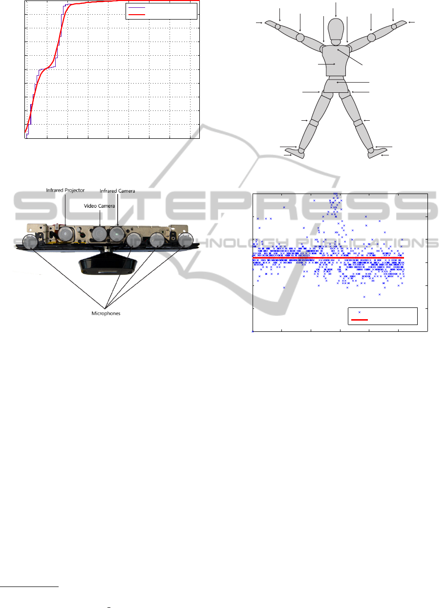
of time. In other words, we want to know the prob-
ability that the sampling period of the Wii Fit is less
than or equal to any given time. Cumulative distribu-
tion function for the Wii Fit data is depicted in figure
4. For example, the probability that the sampling pe-
riod remain less than or equal to 0.02 s is 94.02%.
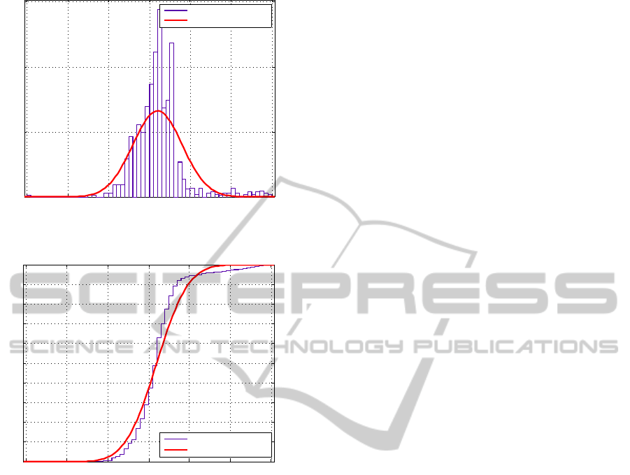
3.2 Microsoft Kinect
Since 2009, when it was announced, the Kinect for
Microsoft Xbox 360 has been widely used in many
applications. The Kinect device is a natural user inter-
face, which allows users to interact with games with-
out physical contact with any command. It was devel-
oped by PrimeSense Company. The user becomes the
controller itself, having to rely on movements, natu-
ral gestures and voice commands to control game el-
ements.
Kinect is equipped with an RGB-D camera that
acquires images of 640x480 at 30 fps. It has a vi-
NEUROTECHNIX2013-InternationalCongressonNeurotechnology,ElectronicsandInformatics
24
0 0.01 0.02 0.03 0.04 0.05 0.06 0.07 0.08
0
0.1
0.2
0.3
0.4
0.5
0.6
0.7
0.8
0.9
1
Cumulative(probability
Measured
Fit (non−parametric)
Sampling period (s)
Figure 4: Cumulative distribution function as a function of
the sampling period (s).
Figure 5: A Kinect camera unwrapped (Miles, 2012).
sual field range from 1.2 to 3.5 meters, but can be
reduced by optical coupling, as Niko Zoom Lenses
R
. Furthermore, its viewing angle is 57
◦
horizon-
tally, and 43
◦
vertically. The vertical visual field
can be expanded 27
◦
with its servomotor. It is also
equipped with an array of four microphones, each
with a recording resolution of 16 bits sampled at 16
kHz. It also contains a stack of signal processing
hardware that is able to handle all the data that cam-
eras, infrared light, and microphones generate. By
combining the output of these sensors, a program can
track and recognize objects in front of it, determine
the direction of the sound signals, and isolate them
from the background noise. The disassembled hard-
ware is shown in Figure 5.
This unique device has not gone unnoticed by the
scientific community. Proof of this is the immedi-
ate development of free SDK such as OpenNI
1
and
OpenKinect
2
, used in many research projects as a
novel human-computer interface, (Brunner, 2012).
The role of the Kinect in the platform is to enrich
1
www.openni.org
2
openkinect.org/wiki/Main Page
Center of hip
Center of
shoulders
Left ankle
Left foot
Left hip
Left knee
Left
wrist
Left
elbow
Left
shoulder
Head
Right foot
Right hip
Right knee
Right
wrist
Right
elbow
Right
shoulder
Right hand
Left hand
Spine
Right ankle
Figure 6: Schematic of the 20 points of the human skeleton
that can track the Kinect (Catuhe, 2012).
Sampling Period (s)
0 200 400 600 800 1000 1200
0
0.01
0.02
0.03
0.04
0.05
0.06
Measured
Measuring Average
Number of samples
Figure 7: Sampling time the Kinect sends data to the PC.
the visual feedback provided to the patient. Com-
mon posturography platforms are limited to provide
users information about the center of pressure but the
user does not know precisely his/her position and how
good it is for the intended task. In this way, the Kinect
provides kinematic information of full body segments
(Figure 6), thus providing more complete information
to users as well to the neuroprosthetic controller en-
abling better actuation commands.
Both the Wii Fit as the Kinect, help to give vi-
sual feedback to the evaluated subject, and the infor-
mation generated can be used by the neuroprosthetic
controller to generate more precise and adequate stim-
ulation patterns. A similar analysis done with the Wii
Fit Board, was carried out with Kinect to evaluate
the jitter effect when acquiring the frames. Samples
taken during a period of approximately 20 seconds are
shown in Figure 7.
The probability density function of the data in Fig-
ure 7 corresponds to a normal distribution pattern,
now depicted in Figure 8. The distribution has a mean
ALowCostPlatformbasedonFESandMuscleSynergiesforPosturalControlResearchandRehabilitation
25
0 0.01 0.02 0.03 0.04 0.05 0.06
0
50
100
150
Sampling period (s)
Density
Measured
Fit (normal distribution)
Figure 8: Probability density function of the sampling pe-
riod kinect.
0 0.01 0.02 0.03 0.04 0.05 0.06
0
0.1
0.2
0.3
0.4
0.5
0.6
0.7
0.8
0.9
1
Cumulative probability
Sampling period (s)
Measured
Fit (normal(distribution)
Figure 9: Cumulative distribution function of the sampling
period Kinect.
of 0.032 s (∼ 30 fps) and a variance of 3.62e-5.
The cumulative distribution function in Figure 9.
For example, the probability that the sampling fre-
quency is maintained below 35 fps is 75%, approx-
imately.
3.3 Posturography Controller
The Posturography Controller is implemented in a
personal computer running Windows 8 operating sys-
tem. The developed software includes traditional pos-
turography tools and tests like Romberg’s test, test of
the stability limits and rhythmic directional test.
The software was developed for easy use by med-
ical personnel. It includes a database in which data of
each patient is stored, allowing the physician to eval-
uate subject progress after several sessions. It also
helps to diagnose and program rehabilitation exercise
routines for each one subject. The application is also
able to generate Matlab scripts containing the center
of pressure points recorded during each rehabilitation
session. In this way, the therapists can analyze data
recorded in previous sessions.
The Posturography Controller receives all the data
from the Kinect camera and the Wii Fit Balance
Board. It fuses and displays the acquired data show-
ing information like the center of pressure, the rigid
body kinematic chain of the studied/analyzed subject,
and information about current routines and tests. This
controller is connected to the Neuroprosthetic Con-
troller thought a TCP/IP connection.
In next sections details of the various parameters
used to quantify the results of each test will be de-
scribed, (Garc
´
ıa, 2012).
• Romberg’s Test. The subject is positioned on the
Wii Fit Balance Board in an upright position with
arms straight and close to the body trying not to
move the head in neutral position facing forward,
bare feet at an angle Opening of 30
◦
. In this po-
sition is assessed for T seconds (configurable by
the doctor) their ability to maintain balance in the
following conditions:
– Eyes Open (REO) and Eyes Closed (REC).
– Foam on Wii Fit with Eyes Open (RGA) and
Eyes Closed (RGC).
The parameters evaluated in each test are:
– Shift angle (degrees). The angle of the vector
extending from the initial point to the subject
portion to the end point of the trajectory.
– Swept Area (mm
2
). It estimates the area swept
by the COP by mean of an ellipse whose axes
correspond to the maximum mediolateral and
anteroposterior displacement.
– Average speed (cm/s). It estimates the average
speed, which is the ratio between the displace-
ment and time T that lasts the test.
– Maximum mediolateral and anteroposterior
displacements (mm). These parameters repre-
sent the longest displacement in the mediolat-
eral and anteroposterior axis during the exer-
cise.
Figure 10 shows a screenshot during the execution
of the application designed in this project. Specif-
ically, this screenshot corresponds to a REO Test.
The figure shows two visual feedbacks. The first
one is the position of the center of pressure on the
Wii Fit Balance Board, and the second, provided
by Kinect, is the RGB image and a trace of its
skeleton. The screen provides information about
subject’s skeleton (skeleton blue) and a given ref-
erence (red skeleton). The reference indicates cor-
rect estimated position during the tests.
NEUROTECHNIX2013-InternationalCongressonNeurotechnology,ElectronicsandInformatics
26
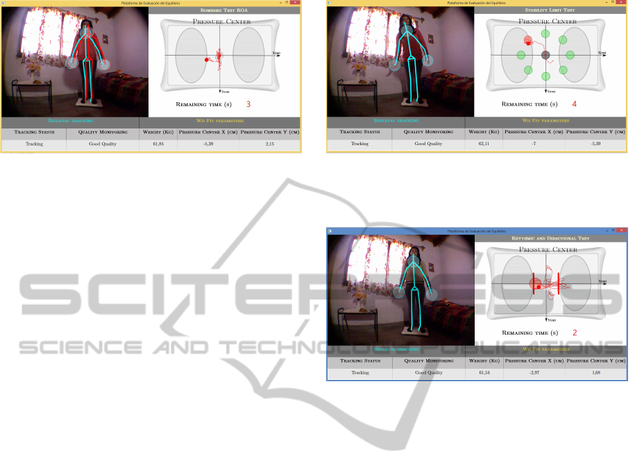
Figure 10: Screenshot during the execution of REO Test.
On the right,it is shown the center of pressure on the Wii
Fit while on the left the subject with his/her skeleton (blue
lines) and the given reference (red lines).
Some parameters are provided in real time by the
application. For example, regarding the Kinect, it
monitors the status of the tracking task, which can
be Tracking (OK) or not skeleton (Subject not de-
tected). Another parameter is the quality of the
skeleton, this parameter indicates if the Kinect
is showing the complete skeleton of the subject
(Good Quality). If the quality is poor, the clini-
cian or therapist can ask the patient to move up,
down, left or right, depending on the case, to get a
better result. This will help the doctor to point the
camera in the correct position. Regarding the Wii
Fit Balance Board, the parameters observed are
subject’s weight and the coordinates of the COP.
• Stability Limit Test. This test evaluates the fol-
lowing parameters:
– LE max (mm). It is the maximum value reached
by the COP in the corresponding direction (8
targets separated of 45
◦
and whose radial dis-
tance from the origin is configurable).
– Stability zone (cm): It is approximately the
mean distance at which the patient is 90 % of
the time. It is calculated for each direction.
Figure 11 shows a screenshot during the execu-
tion of limit test. The variation of the COP on
the Wii Fit for the Limit Test is depicted on the
right side. The red circle represents the current
target to which you should direct your COP, while
the green ones represent those already targeted.
Traces of COPs in these directions have been
deleted to not disturb the patient with current tar-
get.
• Rhythmic and Directional Test. In this test, the
patient is asked to follow the movements of a
moving target (configurable frequency ) in medi-
olateral and anteroposterior directions. The max-
imum excursion limit is calculated based on the
parameters of normal stability limits (previously
recorded with healthy subjects).
Figure 11: Screenshot during the execution of the limit test.
On the right side of the screen, the COP on the Wii Fit is
shown in real time. On the left side is shown the patient
with his/her stickman representation (blue lines).
Figure 12: Screenshot for Rhythmic Test ML execution. On
the right, we see the COP on the Wii Fit. To the left is shown
the patient with his skeleton (blue lines).
The following parameters are evaluated for each
direction.
– Reaction Time (s). It is defined as the time that
the subject takes to bring his/her center of grav-
ity closer than two centimeters from the refer-
ence target.
– Tracking Capability (%). It quantifies subject’s
ability to follow the movement of the target in
ML or AT directions. This parameter is cal-
culated as the mean of error (DesiredCOP −
MeasuredCOP), after the reaction time. If the
error is lower than 2cm (configurable), in other
words the COP is inside the target circle, it is
considered as zero for this sample.
– Directional Control (%): quantifies the sub-
ject’s ability to remain in the expected direction
of the test. For example, if the target moves in
the axis ML, is evaluated AT axis error using
the same process for calculating the tracking
capability.
Figure 12 shows a screenshot during the execution
of the application for Mediolateral (ML) Rhyth-
mic Test. On the right, the screen shows the mov-
ing target.
Figure 13 shows a screenshot during the execution
ALowCostPlatformbasedonFESandMuscleSynergiesforPosturalControlResearchandRehabilitation
27
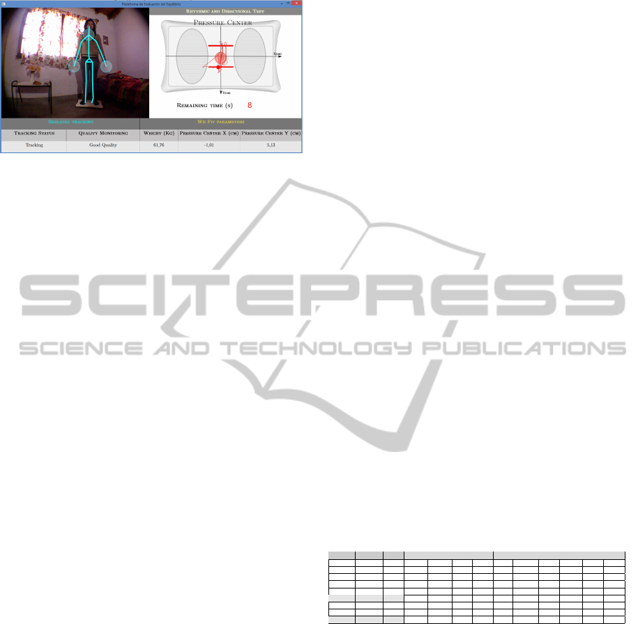
Figure 13: Screenshot for AT Rhythmic Test execution. On
the right, the COP on the Wii Fit is depicted. On the left, it
is shown the subject with his stickman representation (blue
lines).
of the application, more specifically, a anteropos-
terior (AP) Rhythmic Test.
3.4 Neuroprosthetic Controller
The Nueroprosthetic controller is responsible for the
generation of muscle activation patters and for control
of the actuation system: the TEREFES electrostimu-
lator. It receives from the Posturography controller
all the kinematic data of the subject (acquired with
the kinect) and the coordinates of the center of pres-
sure (COP). A driver will decode or convert the in-
formation to muscle activation patterns and specific
TEREFES commands accoding to previously pro-
grammed synergies sets, theory and rehabilitation pa-
rameters. Full detail of the proposed synergistic con-
troller can be found in (Denis et al., 2012)
The functional stimulator TEREFES must act syn-
chronously according with the exerted movements.
This imposes the real-time nature that must fulfill the
Neuroprosthetic Controller. To achieve this and ease
the development of novel controllers a real time Mat-
lab kernel is used. Thus, the delay caused by the Pos-
turography Controller can be determines before gen-
erating actuation command. Further analysis of the
performance of system timing should be realized in
next stages.
3.5 TEREFES
The TEREFES was proposed within the framework
of the TERERE and Hyper projects (Brunetti et al.,
2011). The TEREFES electrostimulator provides up
to 32 stimulation channels driven by controllable and
stable and close loop current sources. In addition, the
system is portable and flexible. This functional stim-
ulator is powered by 4 AA batteries and includes a
USB communication interface that allows its config-
uration via external software. Monophasic and bipha-
sic stimulation signal can be obtained in its 32 avail-
able channels. This channels are divided in two inde-
pendent groups of 16 channels each, that can be stim-
ulates simoultaneously.
4 PRELIMINARY RESULTS
In this section preliminary results of posturography
software are presented. Described results were ob-
tained with 6 healthy people, 4 men and 2 women.
The purpose of this functional validation is to tech-
nically verify the platform and to compare result be-
tween different subjects. Unfortunately, at this stage
of the work, the system could not be tested with previ-
ously diagnosed pathological subjects, and the results
could not be compared with those obtained with other
commercial platforms like Neurocom.
The procedures for the tests were explained in pre-
vious sections. REO and REC tests were conducted,
as well as Stability Limit and Rhythmic tests. All of
them were realized a couple of times in order to make
sure that the subjects understand the test but with-
out producing fatigue or previous learning/training
(Garc
´
ıa, 2012). The sampling frequency was 30
frames/second, enough to detect any COP variation
(Enbom et al., 1988).
4.1 Romberg’s Test
Each Romberg’s test lasted 30 seconds. The results of
the 6 subjects are shown in Table 1.
Table 1: REO and REC Test results.
Subject Sex Years Disp. angle (
◦
) S. Area (cm
2
) A.Speed (cm/s) Disp. ML (cm) Displ. AT(cm)
REO REC REO REC REO REC REO REC REO REC
1 M 23 108,22 114,45 18,28 17,21 1,94 2,28 2,42 3,16 1,82 3,00
2 M 26 90,77 91,45 2,71 6,06 1,25 1,65 0,817 1,552 1,01 1,22
3 M 34 95,89 113,77 12,91 12,52 1,69 2,15 2,46 2,71 2,01 2,31
4 M 47 76,55 75,71 9,05 4,88 1,23 1,34 1,81 1,55 1,85 1,21
Average 92,86 98,84 10,74 10,17 1,53 1,86 1,88 2,23 1,67 1,94
5 F 19 122,49 112,1 4,94 5,85 1,53 1,95 2,06 2,05 1,06 2,45
6 F 18 106,79 103,85 8,99 7,45 1,34 1,65 2,15 2,03 1,13 2,32
Average 114,64 107,96 6,97 6,65 1,44 1,80 2,11 2,04 1,095 2,385
All proposed parameters were calculated and they
are presented in Table 1. Results suggest a decrease
of fine postural control in most subjects when they
close their eyes. For both men and women, the dis-
placement angle is usually in the second quadrant, and
no significant differences are found among REO and
REC tests. In fact, according to (Garc
´
ıa, 2012) this
parameter does not change significantly under these
test conditions.
Figure 14 shows the results of subject 4. Using
similar data, proposed parameters were calculated for
each subject.
Regarding the swept area, calculated by many
professionals in the field according to the literature
(Black et al., 1989), it does not reflect noticeable
NEUROTECHNIX2013-InternationalCongressonNeurotechnology,ElectronicsandInformatics
28
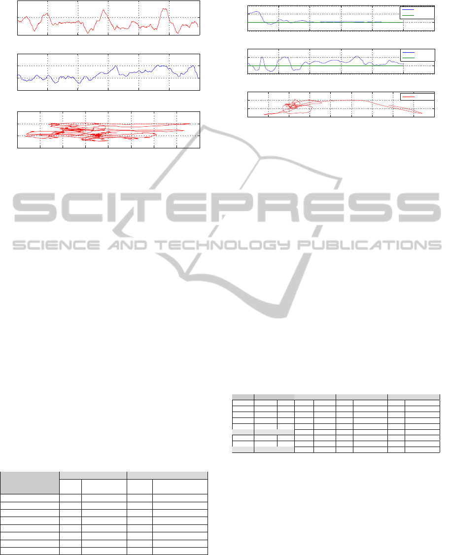
0 5 10 15 20 25 30
0
1
2
Time (s)
COPx (cm)
0 5 10 15 20 25 30
0
2
4
6
Time (s)
COPy (cm)
0 0.2 0.4 0.6 0.8 1 1.2 1.4 1.6
0
2
4
6
COPx.(cm)
COPy.(cm)
Figure 14: Subject 4 (S4) REC Romberg’s test plotted using
Matlab. Parameters for S4 are calculated with these data.
changes with the changing sensory conditions. Bal-
aguer, in his work, (Garc
´
ıa, 2012), has suggested that
the calculation by fitting a geometric figure may not
be adequate to quantify this parameter.
Finally, the average speed of displacement, is
found to increase without visual feedback. This same
behavior is observed in the mediolateral and antero-
posterior displacement. Therefore, these parameters
are used to differentiate visual system impact and po-
tential dysfunction in balance control. Both men and
women present larger variations in the mediolateral
direction, being even larger in men in these particular
tests.
4.2 Stability Limit Test
The stability limit test lasted 10 seconds for each di-
rection, and each target was located at a distance of
10 cm from the origin. The subject was asked to make
his/her best effort to reach the targets.
Table 2: Stability Limit rest results. The average values
are shown. Similar data can be used to obtain normality
patterns.
Average Max. LE (cm) Average Stability Zone (cm)
X
X
X
X
X
X
X
X
X
X
Direction
Sex
Male Female Male Female
Front 7,51 9,04 5,77 8,32
Front-right 9,68 9,695 8,05 8,73
Right 10,59 9,165 9,28 7,70
Rear-right 9,44 8,58 8,92 7,33
Rear 10,06 8,00 8,68 6,915
Rear-left 9,88 9,33 8,32 8,64
Left 11,01 10,05 9,00 8,35
Front-Left 9,335 9,97 8,2675 8,55
Figure 15 shows the results of subject 1. Using
similar data, proposed parameters were calculated for
each subject.
According to these tests, areas of stability in both
men and women vary with direction. In general terms,
0 2 4 6 8 10 12
−20
−10
0
10
Limit Test Results − Left (Session 1)
Time (s)
COPx (cm)
0 2 4 6 8 10 12
−2
0
2
4
Time (s)
COPy (cm)
−14 −12 −10 −8 −6 −4 −2 0 2 4
−2
0
2
4
COPx (cm)
COPy (cm)
Measured
Reference
Measured
Reference
Measured
Figure 15: Subject 1 (S1) Limit Test Results plotted using
Matlab. Parameters for S1 are calculated with these data.
there are no significant differences. These results
agree with (Cort
´
es, 2007). However, a larger popula-
tion is needed to obtain robust conclusions. Balaguer
found that the subject own subjective perception (Pre-
vious Q&A about disability condition of the subject)
of his/her skill or disabilities does not influence the
stability limits, (Garc
´
ıa, 2012).
4.3 Rhythmic and Directional Control
Test
For the rhythmic tests, windows of 10 cm (con-
figurable) long were defined directionally. First in
the mediolateral direction and then in the anterior-
posterior one. The subject was asked to follow a mov-
ing target traveling at a frequency of 0.25 Hz. Each
test lasted 20 seconds. The results are shown in Table
3 for each patient.
Table 3: Test results rhythmic control.
Subject Sex Years Reaction time(s) Tracking capability(%) Directional control (%)
ML AT ML AT ML AT
1 M 23 0,037 0,50 81,86 85,7 81,7 99,9
2 M 26 0,119 0,039 80,55 70,44 90,17 99,05
3 M 34 0,12 1,059 87,7 63,8 78,22 99,83
4 M 47 0,198 1,046 79,6 57,8 77,51 99,92
Average 0,1185 0,66025 82,43 69,43 81,9 99,675
5 F 19 0,40 0,035 66,5 70,23 79,7 98,5
6 F 18 0,42 0,21 71,5 55,26 88,53 96,94
Average 0,4125 0,1225 69 62,74 84,11 97,72
Figure 16 shows the results of the subject 5. Sim-
ilar results were used to calculate all parameters for
each subject.
According to these results, the reaction time in-
creases with age. In addition, there is a shorter reac-
tion time in women. In men, the reaction time is better
in the ML direction with respect to the AT. Although
this work has not made a study of subjects with spe-
cific pathologies, (Garc
´
ıa, 2012) found that vestibular
disorders can affect rhythmic and directional control
in disagreement with the findings of Cort
´
es, (Cort
´
es,
2007).
ALowCostPlatformbasedonFESandMuscleSynergiesforPosturalControlResearchandRehabilitation
29
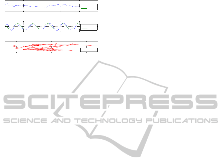
0 5 10 15 20 25
−5
0
5
AT Rhythmic Test Results (Session 1)
Time (s)
COPx (cm)
0 5 10 15 20 25
−10
0
10
Time (s)
COPy (cm)
−1.5 −1 −0.5 0 0.5 1 1.5 2 2.5
−10
0
10
COPx (cm)
COPy (cm)
Measured
Reference
Measured
Reference
Measured
Figure 16: Subject 5 (S5) Rhythmic test Results in the AT
direction plotted using Matlab. Parameters for S5 are calcu-
lated with these data.
5 DISCUSSIONS
Posturography helps to assess the influence of any
vestibular dysfunction in postural and balance con-
trol. However, a pathology that affect the balance in
one patient, in other word the vestibular-spinal reflex,
not necessarily will do it in another one. In this case,
tools like the one described in this work are not effec-
tive for the diagnosis of the impairment.
Regarding the tool presented in this paper, it i
not very clear in the literature the way how differ-
ent assessment parameters are calculated. This lack
of information make more difficult to compare re-
sults. However, overall conclusions and trends ob-
tained with this tool are similar to those reported in
the literature and obtained with other platforms.
Nowadays, there is still a discrepancy between
scientist regarding the results of each parameter and
associated information. According to (Garc
´
ıa, 2012),
this discrepancy exits because it is difficult to find
clear relationships between functional assessment of
balance and patient-perceived disability. Tests may
be influenced by many factors like social, profes-
sional, technical, psychological, affective, and cogni-
tive ones.
The current drawback of classical static postur-
ography is limited only to study the subject during
standing position, so it does not provide information
on the dynamic aspects of postural control. To solve
this shortcoming, we have followed the line proposed
by (Garc
´
ıa, 2012) and set dynamic tests, such as the
rhythmic test.
6 CONCLUSIONS AND FUTURE
WORK
Postural rehabilitation boosts patient confidence and
contribute to their self-improvement. In addition,
knowledge of the particular deficit in postural control
helps clinician and patient to develop prevention plans
to avoid falls, and as mentioned before, it is the first
step towards the rehabilitation of more complex pro-
cesses like gait.
Current research projects in neuromotor rehabili-
tation like Hyper, are devoted to develop novel bioin-
spired rehabilitation treatments. The use of hybrid
solutions including neurorobotics and neuroprosthet-
ics devices has been shown as an efficient approach.
However, the use and development of modern rehabil-
itation therapies based on novel knowledge need the
support of non existing research tools.
We have seen how to make a low cost posturogra-
phy system. It is based on a Wii Fit Balance Board,
the Microsoft Kinect and the TEREFES electrosti-
mumlator. This tool can serve as a low cost balance
control assessment tool and will allow the implemen-
tation of novel therapies that could improve current
ones for the rehabilitation of balance control.
Future work includes the evaluation of the tool and
developed system in clinical environments. After this
validation, the final integration of the neuroprosthetic
controller and the implementation of therapies based
on muscle synergies will be done.
REFERENCES
Baydal, J., Castelli, A., Garrido, J., Bermejo, I., Broseta, J.,
Amparo, M., J, P., and Moya, M. (2010). Nedsve/ibv
v.5 a new system for postural control assessment in
patients with visual conflict.
Black, F., Shupert, C., Peterka, R., and Nashner, L. (1989).
Effects of unilateral loss of vestibular function on the
vest
´
ıbulo-ocular reflex and postural control. Annals of
Otology, Rhinology, and Laryngology, 98:884–889.
Brunetti, F., Garay, A., Moreno, J., and Pons, J. (2011).
Enhancing functional electrical stimulation for emerg-
ing rehabilitation robotics in the framework of hyper
and project. In 2011 IEEE International Conference
on Rehabilitation Robotics Rehab Week Zurich, ETH
Zurich Science. IEEE.
Brunner, S. (2012). Using Microsoft Kinect Sensor to per-
form commands on virtual objects. Master’s thesis,
Polyechnic University of Turin, Italy.
Cai, L., Fong, A., Yongqiang, L., Burdick, J., and Edger-
ton, V. (2006). Assist-as-needed training paradigms
for robotic rehabilitation of spinal cord injuries. In
Proceedings of the 2006 IEEE International Confer-
ence on Robotics and Automation (ICRA’06).
Catuhe, D. (2012). Programming with the Kinect for Win-
dows Software Development Kit. Microsoft Press.
Cort
´
es, O. (2007). An
´
alisis cl
´
ınico y posturogr
´
afico en an-
cianos con patolog
´
ıa vestibular y su relaci
´
on con las
ca
´
ıdas. PhD thesis, University de Valencia, Spain.
NEUROTECHNIX2013-InternationalCongressonNeurotechnology,ElectronicsandInformatics
30

D’Avella, A. and Bizzi, E. (2005). Shared and specific mus-
cle synergies in natural motor behaviors. Proceedings
of the National Academy of Sciences of the United
States of America, 102(8):3076–3081.
D’Avella, A., Portone, A., Fernandez, L., and Lacquaniti, F.
(2006). Control of fast-reaching movements by mus-
cle synergy combinations. Journal of Neuroscience,
26(30):7791–7810. cited By (since 1996) 78.
Del-Ama, A., Koutsou, A., Moreno, J. C., and Pons, J.
(2012). Review of hybrid exoskeletons to restore gait
following spinal cord injury. Journal of Rehabilitation
Research and Development, 49:497–514.
Denis, W., Brunetti, F., Piazza, S., Torricelli, D., and Pons,
J. (2012). Functional electrical stimulation controller
based on muscle synergies. In Proceedings of the
First International Conference on Neurorehabiltia-
tion, Converging Clinical and Engineering Research
on Neurorehabilitation.
Enbom, H., Magnusson, M., Pyykko, I., and Schalen, L.
(1988). Presentation of a posturographic test with
loading of the proprioceptive system. Acta Otolaryn-
gol Suppl., 455:58–61.
Faraldo, A. (2009). Register postural in healthy: evalua-
tion of balance by comparative study of computerized
dynamic posturography and sway star system. PhD
thesis, University of Santiago de Compostela, Spain.
Garc
´
ıa, R. B. (2012). Valoraci
´
on de un m
´
etodo de postur-
ograf
´
ıa est
´
atica con pruebas din
´
amicas para evaluar
funcionalmente pacientes vestibulares en edad labo-
ral y su relaci
´
on con el
´
ındice de discapacidad. PhD
thesis, Polytechnic University of Valencia, Spain.
Khasnis, A. and Gokula, R. (2003). Romberg’s test. Journal
of Postgraduate Medicine, 2:169–172.
Martin, E. A. (2008). Study and development of man-
machine interface based on wirelles sensor. University
Pontificia Comillas.
Miles, R. (2012). Start Here!. Learn Microsoft Kinect API.
O’Reilly Media, Inc.
Piazza, S. (2013). Muscle synergies in postural sway move-
ments: neurophysiologial evidences and reabilitation
potentials. Master’s thesis, University Carlos III of
Madrid, Spain.
Piazza, S., Torricelli, D., Brunetti, F., del Ama, A. J., Gil-
Agudo, A., and Pons, J. (2012). A novel fes con-
trol paradigm based on muscle synergies for postu-
ral rehabilitation therapy with hybrid exoskeletons. In
Proceedings of 34th Annual International Conference
of the Engineering in Medicine and Biology Society.
(EMBC’12). IEEE.
Torricelli, D., Aleixandre, M., Alguacil, I., Cano, R.,
Molina, F., Carratal
´
a, M., Piazza, S., and Pons, J.
(2012). Modular control of mediolateral postural
sway. In Proceedings of 34th Annual International
Conference of the Engineering in Medicine and Biol-
ogy Society (EMBC’12).
Torricelli, D., Moreno, J. C., and Pons, J. L. (2011). A
new paradigm for neurorehabilitation based on mus-
cle synergies. In Proceedings of 34th Annual Interna-
tional Conference of the Engineering in Medicine and
Biology Society. (EMBC’12).
ALowCostPlatformbasedonFESandMuscleSynergiesforPosturalControlResearchandRehabilitation
31
