
Multiple Ontologies Enhanced with Performance Capabilities
to Define Interacting Domains within a Workflow Framework
for Analysing Large Undersea Videos
∗
Gayathri Nadarajan, Cheng-Lin Yang and Yun-Heh Chen-Burger
CISA, School of Informatics, University of Edinburgh, 10 Crichton St, Edinburgh EH8 9AB, U.K.
Keywords:
Intelligent Problem-solving, Process Knowledge and Semantic Services, Applications and Case-studies,
Domain Analysis and Modelling.
Abstract:
In this paper, we describe our efforts in using ontological engineering as a backbone technology to define
multi-disciplinary knowledge that interact with one another in a complex domain. Multiple ontologies were
developed to define these interacting domains. Combined with planning technology, they are used in a three-
layered framework that enables the definition, creation and execution of a workflow management system
based on dynamic user requirements. We report on how such ontologies play a central role in enabling the
workflow system to work consistently and systematically while communicating and collaborating with other
project partner systems. We also extend the capability elements of the ontologies with hardware and software
performance measures. These metrics are valuable factors in improving the overall system’s performance.
1 INTRODUCTION
While the creation and use of multiple ontolo-
gies that covers interacting inter-disciplinary domains
and that requires the involvements of several multi-
disciplinary experts may seem daunting to ontolog-
ical novices, it is vital, if such inter-disciplinary
knowledge needs to be formalised in order to en-
able high quality automation. In the EU-funded
Fish4Knowledge (F4K, 2013) project, we face a com-
plex problem of having to understand and work with
multiple domains. Its goal is to automatically anno-
tate and analyse (live) marine video feeds taken from
coral reefs in the open seas that is outside of south Tai-
wan. Based on dynamic user requirements, the main
tasks of the Workflow Management System (WMS)
is to fetch corresponding video feeds, construct ap-
propriate workflows that execute suitable video and
image processing modules, handle and ensure com-
putational consistency and efficiency, while keeping
the user informed on dynamic progress and final out-
comes. This WMS is enabled from a generic work-
flow framework that is context free. However, be-
ing in the centre of the operations means that the
∗
This research was funded by the European Commis-
sion (FP7 grant 257024) and the Taiwan National Science
Council (grant NSC100-2933-I-492-001) and undertaken in
the Fish4Knowledge project (www.fish4knowledge.eu).
WMS needs to have sufficient knowledge to inter-
act with other project partner systems closely. The
WMS needs to understand and operate within multi-
ple domains: the knowledge of marine biology that
is the subject of studies, the capabilities of different
specialised video and image processing modules and
how they may work with one another, user (marine
biology experts) research interests and how they may
be translated into query tasks for the WMS, as well as
how to communicate with the user interface system
that is the front-end for the user.
In addition, the collected marine videos are now
approaching, and soon will be over, 100TBs. The
phenomena of “big data” continue to push the bound-
aries of computational efficiency, accuracy and con-
sistency as manual processing and even manual er-
ror handling are no longer viable options. In the
EU F4K project, a complex computational environ-
ment with heterogeneous high performance computa-
tional nodes as well as storage solutions have been de-
ployed, remotely at NCHC, Taiwan (Ecogrid, 2013).
These computational resources are shared by all F4K
project partners that are operating from their own
countries, but these resources are also shared with
other external project users that we have no control
or knowledge of. It is therefore vital for the WMS
to understand the structure, capabilities, boundaries
and volatilities of such computational environment,
419
Gayathri N., Yang C. and Chen-Burger Y..
Multiple Ontologies Enhanced with Performance Capabilities to Define Interacting Domains within a Workflow Framework for Analysing Large Undersea
Videos.
DOI: 10.5220/0004643304190426
In Proceedings of the International Conference on Knowledge Engineering and Ontology Development (KEOD-2013), pages 419-426
ISBN: 978-989-8565-81-5
Copyright
c
2013 SCITEPRESS (Science and Technology Publications, Lda.)
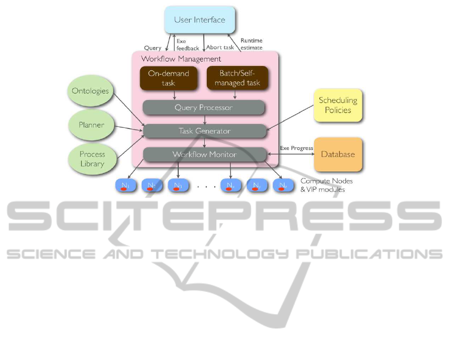
Figure 1: The workflow component binds high level queries from the user interface to low level image processing components
via process planning and composition. It also schedules and monitors the execution of the video processing tasks on a high
performance computing environment and reports feedback to the user interface component.
so that the WMS can perform at its best. In this pa-
per, we introduce the ontology and associated mech-
anisms where we define and detect where problems
may occur and how they may be rectified. The fol-
lowing sessions firstly introduce our workflow frame-
work that enables the running of the Workflow Man-
agement System (Section 2). We then provide a de-
tailed account of our built ontologies and their uses in
the F4K project (Section 3). We show how the capa-
bilities of the system are extended with performance
evaluation measures and conclude the paper with ini-
tial performance analysis of the WMS (Section 4).
2 WORKFLOW FRAMEWORK
The workflow component of the F4K project is re-
sponsible for the composition, execution and monitor-
ing of a set of video and image processing (VIP) mod-
ules on high performancecomputing (HPC) machines
based on user requirements and descriptions of the
video data. It interprets the user requirements (from
the UserInterface component) as highlevel VIP tasks,
creates workflow jobs based on the procedural con-
straints of the modules (VIP components), schedules
and monitors their execution in a heterogeneous dis-
tributed environment (HPC component).
The workflow framework incorporates the knowl-
edge available to the domain (captured in the goal,
video description and capability ontologies) and the
compute environment (hardware resources) available.
The core functions of the workflow are as follows:
1. Perform on-demand workflow queries (high pri-
ority) fromuser interface- compose, schedule, ex-
ecute and monitor jobs. On-demand queries are
the most computationally intensive tasks that the
workflow will have to perform, e.g. fish detec-
tion and tracking and fish species recognition. It
is therefore crucial that latency is minimised for
these types of tasks. The execution of these tasks
will have to be monitored in order to report feed-
back to the user and also to handle exceptions.
2. Perform batch/self-managed workflow queries
(low priority) on unprocessed videos recorded in
the database - compose, schedule, execute and
monitor jobs. These tasks are essentially the same
type of tasks as on-demand queries but are trig-
gered internally by the workflow e.g. daily pro-
cessing of new videos. These tasks are of low pri-
ority and can be run in the background.
3. Perform run-time estimation for a given query
when asked by the user interface. This involves
the calculation of the time estimated for a query to
execute. Several factors will be considered, such
as the number of videos that need to be processed,
the computational intensity of the VIP modules
involved and the availability of HPC resources.
4. Update the database with the progress of execu-
tion for each on-demand workflow query during
short intervals of execution. Thus it can provide
the progress of a workflow query’s execution (as
a percentage) when asked by the user interface.
5. Stop the execution of a task when asked by user
(abort). This would stop the execution of all exe-
cuting subtasks (jobs) of the task.
KEOD2013-InternationalConferenceonKnowledgeEngineeringandOntologyDevelopment
420
The workflow manager’s architecture diagram
(Figure 1) shows an overview of the components that
the workflow interacts with, its main functions, and its
sub-components. As can be seen there are three work-
flow management sub components: 1) Query Proces-
sor; 2) Task Generator; and 3) Workflow Monitor.
The Query Processor deals with high levelprocess
management, such as detecting incoming queries,
processing them accordingly and selecting suitable
computing resource to process on-demand and batch
queries. Multiple queries can be invoked from the
front end which is a web-based user interface. For ex-
ample, “Compute the overall fish population in Lanyu
island cameras from 1st January 2011 to 30th June
2011”. It then deals with breaking down this high
level query into individual VIP tasks that each act on
a video clip. For each camera, 72 10-minute videos
clips are recorded each day. It loops over all the
videos between the start and end dates and over all the
cameras. For each video clip, a sequence of VIP op-
erations are required for this task to be accomplished.
The sequence of VIP operations is composed by
the Task Generator. It is the workflow composi-
tion engine which utilises planning and ontologies.
The workflow composition mechanism was devised
based on a three-layered framework implemented in
an earlier version of the workflow prototype (Nadara-
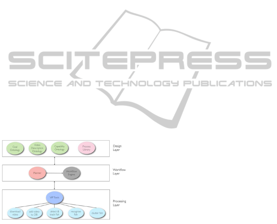
jan et al., 2011). Figure 2 gives a pictorial overview
of the workflow composition framework.
Figure 2: Overview of workflow composition framework
for video processing. It provides three levels of abstraction
through the design, workflow and processing layers. The
core technologies include ontologies and a planner.
The design layer contains components that de-
scribe the domain knowledge and available video pro-
cessing tools. These are represented using ontolo-
gies and a process library. Knowledge about image
processing tools, user-defined goals and domain de-
scription is organised qualitativelyand defined declar-
atively in this layer, allowing for versatility, rich rep-
resentation and semantic interpretation. The process
library developed in the design layer of the workflow
framework contains the code for the image process-
ing tools and methods available to the system. These
are known as the process models. A set of primitive
tasks are identified first for this purpose. A primi-
tive task is one that is not further decomposable and
may be performed directly by one or more image pro-
cessing tools, for instance a function call to a module
within an image processing library, an arithmetic, log-
ical or assignment operation. Additionally, the pro-
cess library contains the decomposition of non primi-
tive tasks or methods.
The workflow layer is the main interface between
the front end and the back end of the F4K system.
It also acts as an intermediary between the design
and processing layers. The main reasoning compo-
nent is an ontology-based planner that is responsible
for transforming the high level user requests into low
level video processing solutions.
The processing layer consists of a set of VIP tools
that can perform various image processing functions.
The functions of these tools are represented in the Ca-
pability Ontology in the design layer. Once a tool
has been selected by the planner to act on a video,
the command line call to invoke the tool on a video
(known as a job) is scheduled for execution via a re-
source scheduler. The set of VIP tools available for
performing various image processing operations are
generated using OpenCV (Intel, 2006) and Matlab
(Mathworks, 2012).
Once a job is scheduled for execution, control is
passed to the Workflow Monitor to oversee its exe-
cution. At any point in time a job can have a status
which is one of “pending”, “running”, “suspending”,
“failed” or “done”. The status is obtained from the
resource scheduler, or triggered by the workflow en-
gine (via a database table field update). Monitoring
ensures that appropriate actions are taken on jobs that
require handling. Scenarios that require handling in-
clude jobs queuing for too long, jobs running for too
long, jobs failing (with an exit code) and jobs being
suspended for too long. When execution is complete,
the results are updated into the F4K database, which
will notify the user interface.
3 Fish4Knowledge DOMAIN
ONTOLOGIES
In our intelligent workflow system, we have adopted
an ontological-based approach (G´omez-P´erez et al.,
2004) to guide the automatic generation of a “vir-
tual workflow machine” based on a set of closely re-
MultipleOntologiesEnhancedwithPerformanceCapabilitiestoDefineInteractingDomainswithinaWorkflow
FrameworkforAnalysingLargeUnderseaVideos
421

lated ontologies. This allows a separation between the
problem and application descriptions and the work-
flow mechanism. As a result, the virtual workflow
machine may work in different problem domains if
the problem and application descriptions are changed.
Consequently, this will promote reusability and pro-
vide a conceptualisation that can be used between dif-
ferent domain experts, such as marine biologists, im-
age processing experts, user interface designers and
workflow engineers. These ontologies are also piv-
otal for reasoning. For instance, in the selection of
optimal VIP software modules, the Capability Ontol-
ogy is used to record known heuristics obtained from
VIP experts.
The Goal Ontology contains the high level ques-
tions posed by the user interpreted by the system as
VIP tasks, termed as goals, and the constraints to the
goals. Based on a mapping between the user require-
ments and a high level abstraction of the capabilities
of the VIP modules, we have constructed the Goal
Ontology. To date, the Goal Ontology contains 52
classes, 85 instances and 1 property. Figure 3 shows
the main concepts derived in the F4K domain. Under
these general concepts, more specific goals may be
defined, for example ‘Fish Detection’, ‘Fish Track-
ing’, ‘Fish Clustering’, ‘Fish Species Classification’
and ‘Fish Size Analysis’. The principle behind keep-
ing the top level concepts more general is to allow the
ontology to be easily extended to include other (new)
tasks as appropriate over time.
Figure 3: Top level goals in the Goal Ontology.
The Video Description Ontology describes the
concepts and relationships of the video and image
data, such as what constitutes the data, the acquisition
conditions such as lighting conditions, colour infor-
mation, texture, environmental conditions as well as
spatial relations and the range and type of their val-
ues. The main class of this ontology is the ‘Video
Description’ class. Example video descriptions are
visual elements such as video/image’s geometric and
shape features, e.g. size, position and orientation and
non-visual elements (acquisitional effects) such as
video/image’s brightness (luminosity), hue and noise
conditions. Environmental conditions, which are ac-
quisitional effects, include factors such as current ve-
locity, pollution level, water salinity, surge or wave,
water turbidity, water temperature and typhoon. The
Video Description Ontology has 24 classes, 30 in-
stances and 4 properties at present.
The Capability Ontology (Figure 4) contains the
classes of video and image processing tools, tech-
niques and performance measures of the tools with
known domain heuristics. This ontology has been
used to identify the tools that should be selected for
workflow composition and execution of VIP tasks
(Nadarajan et al., 2013). The main concepts of this
ontology are ‘VIP Tool’, ‘VIP Technique’ and ‘Do-
main Descriptions for VIP Tools’. Each VIP tech-
nique can be used in association with one or more
VIP tools. A VIP tool is a software component that
can perform a VIP task independently, or a func-
tion within an integrated vision library that may be
invoked with given parameters. ‘Domain Descrip-
tion for VIP Tool’ represent a combination of known
domain descriptions (video descriptions and/or con-
straints to goals) that are recommended for a subset
of the tools. This was used to indicate the suitability
of a VIP tool when a given set of domain conditions
hold at a certain point of execution. The Capability
Ontology has been used for reasoning during work-
flow composition using planning. As planning takes
into account preconditions before selecting a step or
tool, it will assess the domain conditions that hold to
be used in conjunction with an appropriate VIP tool.
The Capability Ontology has been populated with 42
classes, 71 instances and 2 properties.
For ontology development and visualisation pur-
poses, OWL 1.0 (McGuinness and van Harmelen,
2004) was generated using Protege version 4.0.
Where applicable, ontological diagrams were derived
using the OntoViz plugin (Sintek, 2007). They have
supported the first version of the workflow system
that has been evaluated for efficiency, adaptability and
user learnability in video classification, fish detection
and counting tasks in a single-processor (Nadarajan
et al., 2011).
More recent development and preparation of the
KEOD2013-InternationalConferenceonKnowledgeEngineeringandOntologyDevelopment
422
Figure 4: Capability Ontology and its main concepts.
workflow for F4K system’s production run, however,
has led us to carry out more investigations on the fac-
tors that influence the performance of the workflow
system in a heterogeneous multi-processor computing
environment. We will discuss the additional factors in
the next section.
4 EXTENSIONS TO THE
CAPABILITY ONTOLOGY
As explained in the previous section, the Capability
Ontology contains the VIP tools or software compo-
nents available in the domain and their performance
measures in the form of domain descriptions. How-
ever, more recent development and analysis have led
to the discovery that other factors such as the com-
puting resources available to execute the tools and the
performance of the software components themselves
on the available resources play a major role in deter-
mining the overall performance of the system. Fur-
thermore, resource-specific details such as the net-
work traffic and resource’s utlisation and the types
of errors that can occur during scheduling and execu-
tion of the software components also affected the per-
formance of the F4K system. We have added exten-
sions to the Capability Ontology with these factors.
Figure 5 depicts this extension with the addition of
top-levelconcepts ‘Resource’, ‘Performance
Metric’,
‘Resource
Specific Info’ and ‘Error Type’.
Figure 5: Top main concepts of the Capability Ontol-
ogy now include ‘Resource’, ‘Performance
Metric’, ‘Re-
source
Specific Info’ and ‘Error Type’.
In the following two subsections, we will present
the extensions that have been implemented within
the system - Resource (Section 4.1) and Performance
Metrics (Section 4.2). Error types and resource-
specific information are still being explored.
4.1 Computing Resources
The F4K computing environment is a heterogeneous
platform made up of a group of virtual machines (VM
cluster) and a supercomputer (Windrider). The VM
MultipleOntologiesEnhancedwithPerformanceCapabilitiestoDefineInteractingDomainswithinaWorkflow
FrameworkforAnalysingLargeUnderseaVideos
423

cluster contains nine nodes with machines of different
specifications. Windrider consists of seven working
queues of different capacities at present. These are
represented in Figure 6.
On the VM cluster, the resource scheduler is able
to distribute the jobs onto the nodes based on their
availability. On Windrider, however, the workflow
will have to select a specific queue to submit a job to.
It has to be able to send the job to the highest capacity
queue with the least pending jobs. Hence, we plan to
make use of resource-specific information such as its
hardware specification, the node utilisation, network
traffic and queue capacity to enhance the utilisation of
resources.
Figure 6: The ‘Resource’ class and its subclasses in the Ca-
pability Ontology.
Other than the hardware capabilities, the software
utilisation is also vital in performance analysis.
4.2 Performance Metrics
A software component that is queued, executed and
monitored on a resource can yield indicative perfor-
mance metrics. This includes its average waiting time
on a queue, its execution time on a machine, its max-
imum execution time, its minimum execution time,
its overall success rate (completed successfully) and
its average database waiting time. Figure 7 shows the
performance metrics related to a software component.
In order to analyse the overall performance of
each software component, the performance metrics
statistics are updated on a daily, weekly and monthly
basis. The statistics computed for each software com-
ponent requires the following data from the database:
Figure 7: The addition of the ‘Performance Metric’ class
and its subclasses to the Capability Ontology.
• total number of processed videos: The total num-
ber of processed videos is the foundation for com-
puting the performance metrics. Hence, it is
crucial to have the correct count. In the F4K
database, all the processed videos are recorded in
a table called processed
videos. The remaining
fields are also derived from the same table.
• insert
time: Indicates the date time when a job is
scheduled by the workflowsystem onto the queue.
• start
time: Indicates the date time when a job
starts executing.
• end
time: Indicates the date time when a job fin-
ishes executing.
• last
update: Indicates the date time when the
database was last updated.
• status: Indicates the overall processing status of
the video. The status can be “pending”, “run-
ning”, “completed” and “abandonedByUser”.
• progress: The percentage of the task completed at
a time (0-100). This is updated regularly during
execution.
To ensure that only the successfully completed
tasks are taken into account, several constraints must
be met in order to calculate the performance metrics:
• The video status must be marked as “completed”
in processed
videos table.
• The processing progress must be 100 in pro-
cessed
videos table.
• start
time and end time cannot be null.
• end
time should be larger than start time.
Finally the performance metrics are evaluated:
1. Average execution time
The average execution time of a component, exe,
is calculated by:
exe = (end
time− start time)/total videos
It gives the overall performance of a software
KEOD2013-InternationalConferenceonKnowledgeEngineeringandOntologyDevelopment
424

Table 1: The performance metrics of two main software components (IDs 54 and 80) in F4K.
Component Avg. Execution Avg. Waiting Max. Execution Min. Execution DB Waiting
ID Time (s) Time (s) Time (s) Time (s) Time (s)
54 301 271 2676 9 792
80 3243 17875 82673 2 7332
component over all the machines. This helps the
workflow in two ways: i) It can use this to com-
pute the runtime estimation for a task using this
component; and ii) It can select the most opti-
mal tool to process a user query in a time-efficient
manner.
2. Average waiting time
The average waiting time of a component, wait, is
the time that the job waits in the queue before it
starts execution:
wait = (start
time− insert time)/total videos
This gives an indication of how efficiently the
resource scheduler can handle the scheduled
jobs. This metric helps with workflow monitor-
ing which can then take appropriate actions when
a job has been waiting for too long, such as sched-
ule it on a differentqueue, or suspend unimportant
executing jobs.
3. Maximum and minimum execution time
Sometimes, a video is processed within an
unreasonable time (e.g., less than 3 seconds or
longer than 5 hours). Such cases are outliers that
need to be detected by the system to trace the
root cause for their occurrences. The maximum
execution time, max exe and minimum execution
time, min exe are given by:
max
exe = max(end time − start time)
min
exe = min(end time− start time)
We can also derive the specific video associated
with themaximum and minimum executingtimes.
This allows for more informed error diagnosis.
4. Success rate
When a job is submitted to the resource sched-
uler, it will be assigned to a computing node based
on the scheduling policy. Although the system
configuration and installed packages are identi-
cal on each node, a job can still fail due to hard-
ware and/or software errors. The workflow per-
formance evaluation system keeps track of the job
execution successful rate on each node per soft-
ware component. It helps identify the problem-
atic nodes to avoid more jobs from failing. The
success rate of a software component, success, is
calculated by:
success =
num
successful jobs
total processed videos
x100
5. Database waiting time
When a software component finishes processing a
video, the end
time field in the processed videos
table is updated. After this point, results associ-
ated with the processing will be updated in the
database. Upon completion of the results’ update,
the last
update field in the processed videos
table is also updated. The database waiting time,
db
wait is given by:
db
wait = last update− end time
We have gathered statistics for the performance
metrics related to specific software components. Ta-
ble 1 shows the aggregation for two major software
components that have been used in the production run
to run the same task (fish detection and tracking). It
can be seen that component 54 on average executes
90.72% faster, takes 98.48% less time in the queue
and is 89.2% quicker in the database than component
80. It is a more optimal choice for the workflow.
Table 2: Percentage of success rate of two main software
components (IDs 54 and 80) on four different computing
machines.
ComponentVM ClusterWindriderVM ClusterWindrider
ID gad201 node1 gad202 node2
54 100 0 100 0
80 0 100 0 96.55
Table 2 shows the breakdown of the success rate
of two software components in four different comput-
ing resources. It shows that component 54 was exe-
cuted on the VM cluster while component 80 was ex-
ecuted on Windrider. The success rate indicates how
well a software components executes on a particular
resource, The reason for a rate of 0% could mean that
the resource is not well equipped with the libraries re-
quired for that component. It could also mean that
a task using the particular component has not been
allocated to this resource. This can be distinguished
by observing the total number of videos used for the
computation.
We are continuing our efforts in improving the
overallsystem’s performanceby conducting more rig-
orous analysis on the components over more data and
time. Currently we are working on the error types
MultipleOntologiesEnhancedwithPerformanceCapabilitiestoDefineInteractingDomainswithinaWorkflow
FrameworkforAnalysingLargeUnderseaVideos
425

and handling, and will continue to work on obtaining
resource-specific metrics such as resource utilisation
and network traffic. The Capability Ontology will be
populated with these metrics.
5 CONCLUSIONS
We have implemented a set of domain ontologies for
a multi-disciplinary project involving marine biolo-
gists and computer scientists. The ontologies have
been a backbone technology in representing interact-
ing knowledge in a complex domain. We have shown
how the ontologies, coupled with planning, play a vi-
tal part in a workflow management system that au-
tomatically composes, schedules and monitors video
processing tasks in a time-efficient manner using a
distributed heterogeneous computing platform. The
workflow interacts with a set of partner systems to
ensure the seamless integration of all the processing
components in F4K. We have extended the capability
element of the ontologies with performance measures
that take into account resource and software metrics
and demonstrated the initial performance evaluation
of the workflow management system.
REFERENCES
Ecogrid (2013). National Center for High Perfor-
mance Computing (NCHC), Taiwan. http://ecogrid.
nchc.org.tw.
F4K (2010-2013). The Fish4Knowledge Project. http://
www.fish4knowledge.eu.
G´omez-P´erez, A., Fern´andez-L´opez, M., and Corcho, O.
(2004). Ontological Engineering. Springer.
Intel (2006). Open Source Computer Vision (OpenCV) Li-
brary. http://sourceforge.net/ projects/opencvlibrary.
Mathworks (1994-2012). MATLAB - The Language
of Technical Computing. The MathWorks Inc.
http://www.mathworks.com/products/matlab.
McGuinness, D. and van Harmelen, F. (2004). OWL Web
Ontology Language. World Wide Web Consortium
(W3C).
Nadarajan, G., Chen-Burger, Y. H., and Fisher, R. B.
(2011). SWAV: Semantics-based Workflows for Au-
tomatic Video Analysis. In Special Session on Intelli-
gent Workflow, Cloud Computing and Systems, (KES-
AMSTA’11).
Nadarajan, G., Chen-Burger, Y. H., and Fisher, R. B.
(2013). Semantics and Planning Based Workflow
Composition for Video Processing. Journal of Grid
Computing, Special Issue on Scientific Workflows. (in
press).
Sintek, M. (2007). OntoViz. http://protegewiki.stanford.
edu/wiki/OntoViz.
KEOD2013-InternationalConferenceonKnowledgeEngineeringandOntologyDevelopment
426
