
A Double-differential Actuation for an Assistive Hip Orthosis
Specificities and Implementation
Jeremy Olivier, Mohamed Bouri and Hannes Bleuler
Laboratory of Robotic Systems (LSRO), Swiss Federal Institute of Technology Lausanne (EPFL), Lausanne, Switzerland
Keywords: Exoskeleton, Assistive Technology, Lower Limb, Hip, Dual-differential Actuation.
Abstract: The population ageing implies an increasing need for support especially in terms of mobility. Actuated
orthoses offer new possibilities to assist walking by compensating the diminished muscular force which
occurs with age. In order to assist efficiently the user, the orthotic device needs to provide torque without
constraining the voluntary movements. Transparency is therefore a critical characteristic. A first
implementation of such a device using a conventional actuation is presented and its limitations are analyzed.
The walking trajectory being a cyclic movement, the actuator often needs to accelerate and decelerate. Its
dynamics is therefore crucial and can be problematic at the higher cadences. Dual-differential actuation is
therefore presented as a profitable alternative to overcome these weaknesses.
1 INTRODUCTION
Mobility is often a central problem for elderly
people. The consequences of having difficulties to
walk have an impact on both physical health and
psychological well-being. With the population
ageing, the need for walk assistive devices becomes
therefore a central question.
Various exoskeletons have been developed for
different walking assistance and rehabilitation
applications (Herr, 2009). Devices such as the
Lokomat (Jezernik et al., 2003) or the WalkTrainer
(Bouri et al., 2006); (Stauffer et al., 2009) have
demonstrated their value in particular with spinal
cord injured patients. Their main characteristic is
that they mobilize the wearer’s leg in order to
reproduce a walking trajectory. These exoskeletons
therefore mainly act as admittances.
Unlike mobilization devices which impose a
movement to a user who is not able to move by
himself, an assistive orthosis needs to work in
collaboration with the user. To enable the wearer to
lead the movement, the orthosis needs to act as an
impedance (Vallery et al., 2008). In the extreme case
if the assistance rate tends to zero, the device needs
to be fully transparent. As a consequence, it is
required that the actuation mechanism is back-
drivable and ideally entirely dynamically
compensated.
The mechanism also needs to be dynamic
enough to be able to follow the movement of the
users in any situations. Walking being an cyclic
movement, the orthotic device needs to be able to
accelerate and decelerate accordingly to the user’s
motion (Ryder and Sup, 2013).
In order to be as light and as less intrusive as
possible, we propose to develop devices to study the
influence of single joint assistance. Therefore, this
paper presents two different mechanisms to assist
the movement of the hip.
2 METHODS
In this paper we describe two variants of assistive
hip orthoses which were developed in the
Laboratory of Robotic Systems (LSRO). The second
one was developed to overcome limitations of the
first variant.
The first variant is presented in section 3. The
biomechanical considerations are explained and the
design is described. The back drivable actuation
based on a ball-screw is detailed and the limitations
due to this transmission are presented. Typical
walking trajectories were used to assess the dynamic
capabilities of the device.
In section 4, a concept to overcome the
limitations of the first variant is presented. This
183
Olivier J., Bouri M. and Bleuler H..
A Double-differential Actuation for an Assistive Hip Orthosis - Specificities and Implementation.
DOI: 10.5220/0004644601830189
In Proceedings of the International Congress on Neurotechnology, Electronics and Informatics (RoboAssist-2013), pages 183-189
ISBN: 978-989-8565-80-8
Copyright
c
2013 SCITEPRESS (Science and Technology Publications, Lda.)
solution based on a dual-differential actuation is
explained in details and a possible implementation in
an orthotic device is presented in section 5.
3 FIRST VARIANT OF THE HIP
ORTHOSIS
The first variant of the hip orthosis is based on
biomechanical considerations such as the required
torque (depending on the activity the user is
performing), the velocity of the movements or the
articulation range of motion (Olivier et al., 2013).
This orthosis is designed to assist the
movement in the sagittal plane without constraining
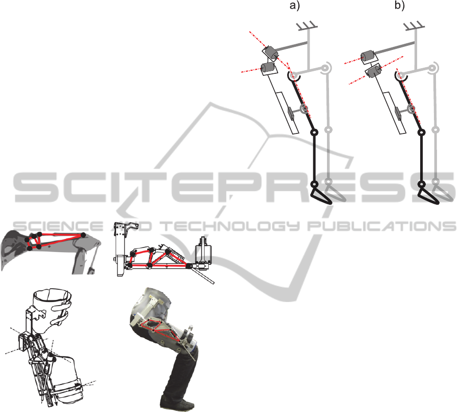
the other rotations of the leg. The mechanism we
implemented to achieve a large range of motion and
a variable transmission ratio is inspired by
excavators (see fig. 1). It uses a DC motor with a
ball screw transmission.
Figure 1: Amplification mechanism inspired by an
excavator. This enables a large range of motion and the
transmission ratio is adapted for walking as well as for
standing up.
3.1 Torque and Velocity
Considerations
The orthosis is aimed to assist the wearer during
walking, stair climbing/descending and during the
sit-to-stand transitions. The later requiring more
torque especially during the first part of the
movement (i.e. when the flexion angle of the hip is
large), the mechanism is designed to offer a variable
transmission ratio. During walking the flexion angle
stays fairly small but a higher velocity is required.
The smaller transmission ratio is therefore fully
adapted to these requirements.
Figure 2: Kinematics of the orthosis. Six degrees of
freedom are required. (a) Position of the joint in the first
prototype. (b) Improved position of the rotational joints.
With this configuration, the axes of rotation are always
quasi-orthogonal (at least within the range of motion).
3.2 Kinematic Considerations
The hip joint can be well approximated by a
spherical joint with its center being the head of the
femur. Three rotations around this point are
therefore considered. Aligning the mechanism’s
rotations with the head of the femur being relatively
complex, we decided to add three degrees of
freedom (DOF) in our mechanism in order to satisfy
the well-known Chebychev-Grübler-Kutzbach
criterion. The mechanism being placed in parallel
with the user’s hip joint, a loop in the kinematic
chain is created. In order to keep the initial mobility,
the mechanism’s number of DOF must be six. Two
rotational DOF are therefore placed at the fixation
with the pelvis and four (one translation and three
rotations) are located at the thigh’s interface (see fig.
2(a)).
3.3 Performances & Limitations
The orthosis was designed to satisfy several
activities’ requirements. Distinct data are then
important to evaluate the performances and the
limitations of the orthotic device. The maximal
torque is a key value for the evaluation of the sit-to-
stand transitions assistance. The velocity can be a
limiting factor during dynamic movements like
NEUROTECHNIX2013-InternationalCongressonNeurotechnology,ElectronicsandInformatics
184
walking. The dynamic capabilities also determines
the maximal assistance rate for walking. Eventually,
the range of motion is of a major importance for the
comfort in general.
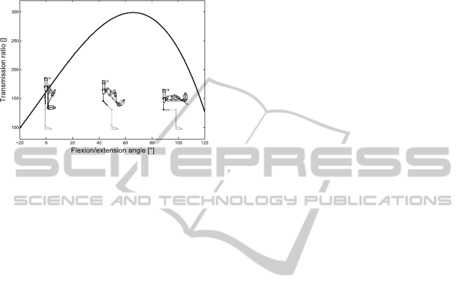
Figure 3: Transmission ratio as a function of the angle in
the sagittal plane. In the walking range the transmission
ratio is smaller. During standing up, the maximum torque
is required when the angle is around 70°. The orthosis has
is maximum transmission ratio in this range.
3.3.1 Maximal Torque and Velocity
As explained in section 3.1 a higher torque is
required when the flexion angle is large (typically
around 70°) for sit-to-stand transitions assistance.
Fig. 3 shows the transmission ratio of the
mechanism as a function of the position of the leg.
During walking the peak torque is lower but the
velocity is higher.
3.3.2 Assistance Rate
The assistive capabilities of the developed orthosis
were evaluated by testing its dynamic performances.
A typical flexion/extension trajectory was used in
order to assess the required torque to make the
orthosis follow the wearer during walking. The
maximum assistive rate is deduced from the
difference between this torque and the maximum
continuous torque that the motor can provide. It was
observed that the maximal assistive rate is around
30% for a 70 kg subject walking at a cadence of 100
steps/min. This rate drops to zero when the cadence
increases to 120 steps/min. In that case the actuation
mechanism (motor and transmission) needs all its
power to accelerate and decelerate its own inertia.
For more information, refer to (Olivier et al., 2013).
3.3.3 Limitation Due to the Kinematics
The amplification mechanism being relatively long,
the joint enabling the flexion/extension movement
had to be placed in second position in the kinematic
chain (see fig. 2(a)). This configuration is sub-
optimal because the rotation in the frontal plane gets
locked when the flexion angle increases. Moreover,
it causes a singularity when the thigh axis and the
first pivot joint are aligned. This generates an
internal degree of freedom − the mechanism having
the possibility to rotate around the leg. This would
not happen if the two rotational joints had their
positions inversed (see fig. 2(b)). Indeed, the
rotation in the frontal plane being limited, no
singularity can be reached. In our first design the
parasitic rotation is prevented by a cam mechanism.
3.4 Control
As the orthosis is intended to assist (in opposition to
mobilization devices), it needs to act as an
impedance. In the extreme case, the impedance is
null and the device is transparent (zero assistance).
To reach this very low impedance, frictional and
dynamic effects are compensated. Therefore a
precise model is required. Since the frictional effects
are difficult to model precisely (in particular dry
friction when the velocity is close to zero), the
transparency is not perfect. As suggested by Zanotto
et al. (Zanotto et al., 2013), force sensors placed on
the supporting cuffs could be employed in order to
improve transparency.
4 DUAL DIFFERENTIAL
ACTUATION
In order to limit the inertia effect and the substantial
induced power consumption, we propose to use a
mechanism which enables to decouple the actuator
from the output. As suggested by Tucker and
Gassert (Tucker and Gassert, 2012), a differential
mechanism could be integrated in a portable lower
limb orthotic device. One of the main advantages of
this kind of actuation is that the output torque can be
controlled independently from the input speed of the
actuator. Another advantage is that a rotational
actuation can be employed which would make
possible the implementation of the improved
kinematics.
4.1 Clutch Principle
In order to avoid any undesired inertial or frictional
effects amplified by a large transmission ratio
ADouble-differentialActuationforanAssistiveHipOrthosis-SpecificitiesandImplementation
185
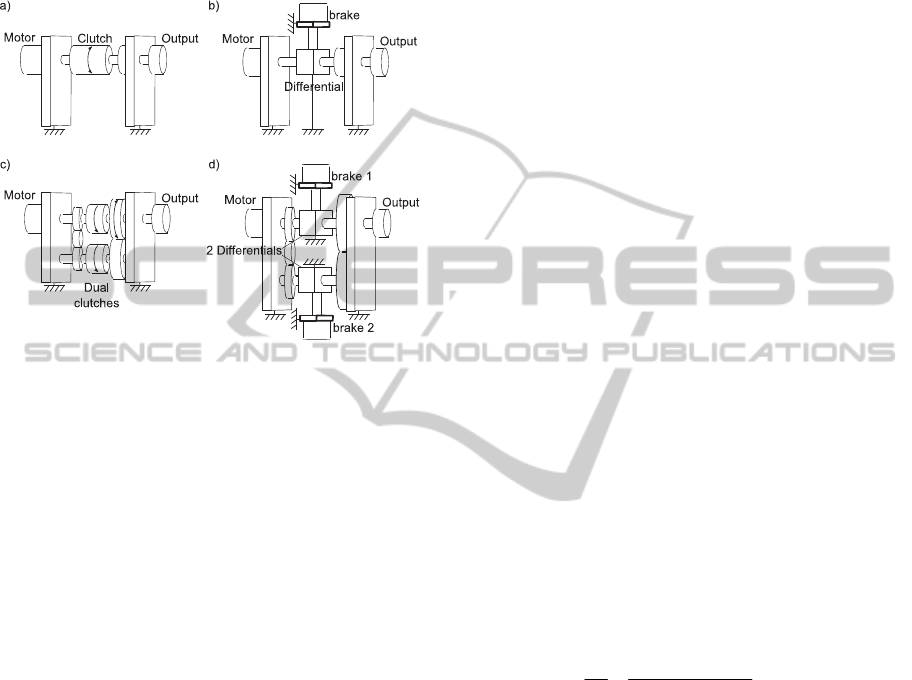
(especially in a transparent mode), a motor/clutch
mechanism can be used (see fig. 4(a)). If the motor
is controlled as a velocity source, the absolute value
of the output torque depends only on the clutch. Its
direction however can only be in the direction of the
actuator velocity.
Figure 4: Clutch mechanisms. (a) Conventional clutch.
The input and the output can be decoupled. (b) Differential
and brake used as a clutch. (c) Dual-clutch mechanism. By
means of two clutches it is possible to control the output in
the two directions with an input rotating in one direction.
(d) Dual-differential mechanism. It is a combination of the
double clutch with the differential and brake mechanism.
4.1.1 Differential Mechanism
As mentioned by Chapuis et al., (Chapuis et al.,
2007), a special case of the clutch principle can be
realized with a differential and a brake (see fig.
4(b)). The main advantage of using a differential is
that the transmission ratio of the motor can be
adapted directly.
4.1.2 Double Clutch Principle
As presented in section 3.3.2, with a conventional
actuation, a substantial amount of power is
consumed to accelerate and decelerate the motor and
its transmission. By using an inversion mechanism
and two clutches it is possible to avoid these
considerable losses. Fig. 4(c) shows the double
clutch configuration. The output torque is the
difference between the torques of the two clutches.
Usually, if one of them is engaged, the second one
should be off, in order to prevent losses. If the motor
is controlled as a constant velocity source, the two
clutches are used to generate the torque in both
directions (Chapuis et al., 2007).
4.1.3 Dual-differential Principle
By combining the double clutch principle with the
differential, a dual-differential actuator is formed.
This solution was implemented by Fauteux et al.
(Fauteux et al., 2010); (Fauteux et al., 2009) using a
velocity source (DC motor and its reduction gear)
and two magneto-rheological brakes.
4.2 Dual-differential Implementation
The differential involves a transmission ratio. By
taking advantage of it, a fairly compact solution can
be designed. This also enables us to have a different
transmission ratio depending on the direction. This
is an interesting feature in our case since, in elderly
walking, the extension torque is greater than the
flexion torque (JudgeRoy et al., 1996).
5 PRACTICAL REALIZATION
A differential mechanism can be realized in different
ways. We implemented ours as a planetary reduction
gear with two external satellites (see fig. 5(a)). The
mechanism is used twice with two different
transmission ratios, one of which being negative in
order to be able to produce torque in both directions.
5.1 Differential based on Planetary
Reduction Gear
The reduction ratio of the implemented planetary
reduction gear is given by:
)r)(rr(r
rr
θ
θ
i
3221
42
4
0
(1)
where, θ
0
is the angle of the input (e.g. the motor), θ
4
is the angle of the output (e.g. the part attached to
leg) and r
1
, r
2
, r
3
, r
4
are the radii of the different
gears as presented on fig. 5(a)
.
In a planetary reduction gear, one of the gears is
fixed to the frame (gear number 1 on fig. 5(a)). In
order to transform this mechanism into a differential,
the gear needs to be movable and the torque applied
on it will enable the control of the output torque
(Fauteux et al., 2010).
An advantage of the planetary reduction gear
with two external satellites is that the transmission
ratio can be negative (see equation 1). Indeed if the
radius r
3
is greater than r
2
, the output is in the
opposite direction than the input. This feature is
exploited to avoid the need for an inversion
NEUROTECHNIX2013-InternationalCongressonNeurotechnology,ElectronicsandInformatics
186
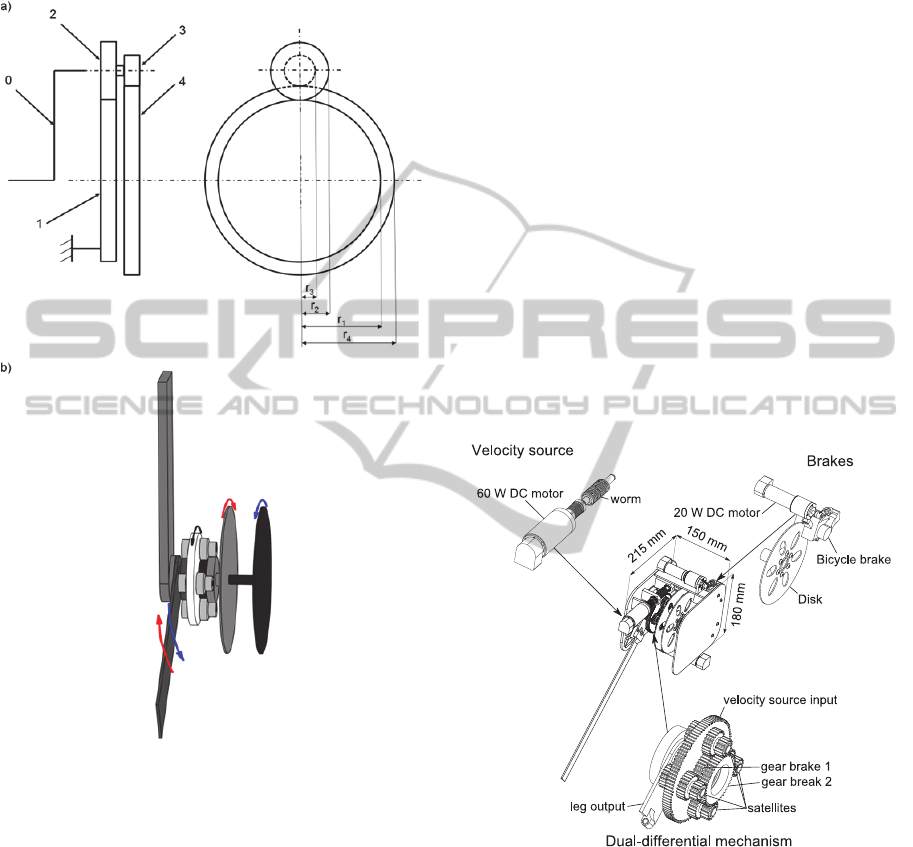
mechanism on the motor side (see section 4.1.2). A
schematic representation of the dual-differential
based on the planetary reduction gear is presented on
fig. 5(b).
Figure 5: Differential mechanism for an orthosis. (a) The
planetary reduction gear with two external satellites. In the
case of a reduction gear, the gear number 1 is attached to
the frame. (b) Implementation of a double differential
mechanism. The motor rotates always in the same
direction (black arrow). The brakes apply torques (red and
blue arrows). These torques are transferred to the part
attached to the leg.
5.2 Actuation
The actuation gear (velocity source) is powered by a
DC motor through a worm gear. The non-back
drivability is not an issue as we only use this motor
as a velocity source and the output can be
decoupled.
The transmission ratio between the motor and the
output (calculated with the transmission ratio of the
worm gear and eq. 1) is equal to 209 in one direction
and to −140 in the other. The theoretical torques
with a 100% efficiency are therefore respectively
18.4 Nm and −12.4 Nm for a nominal input toque of
the motor. Since we are using a DC motor, this
torque can be higher for a short period of time if
required.
Considering that the efficiency of the
transmission is around 50% mainly because of the
worm gear, the RMS assistance torque is around 9
Nm. This torque typically represents around 40% of
assistance for a 70 kg person walking at a cadence of
100 step/min. At the same cadence, this is about
25% more efficient than the first variant.
The brakes are cable driven bicycle disk brakes
and they generate the rated output torque (there is a
transmission ratio between the brakes and the
output). Two 20W DC motors are used to control the
torque. This solution was chosen in order to validate
rapidly the concept. A more compact and reliable
solution will be evaluated for the next version.
The different components of the mechanism are
presented on fig. 6.
Figure 6: Hip orthosis with a double-differential actuation.
The different components which constitute the mechanism
are a velocity source (composed by DC motor and a worm
gear), two disk brakes and the dual-differential
mechanism.
5.3 Improved Kinematics
The developed mechanism makes the
implementation of the kinematics presented on fig.
2(b) possible. The first rotational joint (actuated by
the double-differential mechanism) corresponds to
flexion/extension. The second joint enables the
ADouble-differentialActuationforanAssistiveHipOrthosis-SpecificitiesandImplementation
187
adduction/abduction. Since the range of motion of
this rotation is limited to relatively small angles
(typically 10° for adduction and 30° for abduction)
no singularity can be reached. Another advantage of
this kinematics is that the overall range of motion is
bigger since a combination of large flexion angles
with abduction or adduction is now possible.
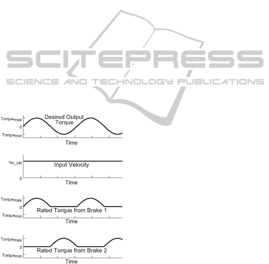
5.4 Control
As explained in section 4, the main advantage of the
dual-differential actuation is that the input (velocity
source) does not have an impact on the output
torque. The restriction is that the rated output
velocity must be less important than the input. Under
this condition, the output torque is the sum of the
rated torques on the brakes (see fig. 7). Ideally the
two brakes do not act simultaneously as this would
unnecessarily increase the energy consumption of
the system. Moreover, as the output torque depends
only on the torques of the brakes, transparency is an
intrinsic characteristics of the system. Indeed when
the brakes are open, the output is free. In addition,
only the characteristics of the brakes need to be
considered to be able to precisely control the output
torque.
Figure 7: Graph showing the control inputs of the brakes
to generate a sinusoidal torque. The velocity source does
not need to adapt to the changes. In order to limit losses
the brakes should not provide torque at the same time. For
a positive output torque, the first brake will be engaged.
The second brake will be used if a negative torque is
required.
Another very important feature of the mechanism
is that in case of power failure, the system becomes
transparent which makes it safer than the
exoskeletons with conventional actuation.
6 CONCLUSIONS
In this paper we have presented two variants of
assistive hip orthoses. The first one was developed
to provide a torque which is adapted to the activity
the user is performing. The transmission ratio of this
device is variable in order to provide an increased
torque for sit-to-stand transitions and more velocity
for dynamic movements like walking. Due to the
inertia of the system, the assistance rate for walking
depends on the cadence (i.e. the number of steps per
minutes) and is therefore reduced at higher speeds.
The transparency of the system is as well limited
since it depends directly on the precision of the
model.
The second variant uses a new type of actuation
based on a novel dual-differential mechanism. It is
presented as an alternative which overcomes the
limitations concerning the kinematics and the rate of
assistance at higher cadences. The output torque can
be directly controlled by applying the corresponding
rated torque on the brakes. In addition, the direction
of the output torque is specified by using one brake
or the other (i.e. one brake is used for flexion and the
other for extension). This method has an additional
intrinsic safety property as it decouples the motor
automatically from the load in case of power failure.
As a consequence, the system becomes transparent
and the risk of accident is significantly reduced.
The two described devices are fairly powerful as
we want to be able to provide a large range of
assistance rate. As a consequence, their size and
weight are also important (about 4 kg for one side).
For later versions, a tradeoff will have to be found in
order to assist efficiently the seniors while limiting
the dimensions and weight of the orthosis as this
could have a negative impact on their balance or on
their coordination.
Further tests will be done with the two devices
worn by subjects in order to validate the effects on
walking or on other related activities. Both of them
are useful platforms for testing different assistive
strategies. The first one is very promising for testing
the effects of partial assistive orthosis on sit-to-stand
transitions while the second one is more adapted for
dynamic and cyclic activities like walking.
NEUROTECHNIX2013-InternationalCongressonNeurotechnology,ElectronicsandInformatics
188

ACKNOWLEDGEMENTS
This research was supported by the National Center
of Competence in Research Robotics (NCCR
Robotics).
REFERENCES
Bouri, M., Stauffer, Y., Schmitt, C., Allemand, Y.,
Gnemmi, S., Clavel, R., Metrailler, P. & Brodard, R.
The Walktrainer: A Robotic System for Walking
Rehabilitation. International Conference on Robotics
and Biomimetics Robio, 2006. IEEE, 1616-1621.
Chapuis, D., Michel, X., Gassert, R., Chew, C.-M.,
Burdet, E. & Bleuler, H. A Haptic Knob with a Hybrid
Ultrasonic Motor and Powder Clutch Actuator.
Eurohaptics Conference, 2007 And Symposium on
Haptic Interfaces for Virtual Environment And
Teleoperator Systems. World Haptics 2007. Second
Joint, 2007. IEEE, 200-205.
Fauteux, P., Lauria, M., Heintz, B. & Michaud, F. 2010.
Dual-Differential Rheological Actuator For High-
Performance Physical Robotic Interaction. Robotics,
IEEE Transactions on, 26, 607-618.
Fauteux, P., Lauria, M., Legault, M.-A., Michaud, F. &
Lavoie, M.-A. 2009. Dual Differential Semi-Active
Actuator Fit For Interaction Tasks And Fast Motion.
Google Patents.
Herr, H. 2009. Exoskeletons And Orthoses: Classification,
Design Challenges and Future Directions. Journal Of
Neuroengineering and Rehabilitation, 6.
Jezernik, S., Colombo, G., Keller, T., Frueh, H. & Morari,
M. 2003. Robotic Orthosis Lokomat: A Rehabilitation
And Research Tool. Neuromodulation: Technology at
the Neural Interface, 6, 108-115.
Judgeroy, J. O., Davis, B. & Õunpuu, S. 1996. Step
Length Reductions in Advanced Age: The Role Of
Ankle and Hip Kinetics. The Journals of Gerontology
Series A: Biological Sciences and Medical Sciences,
51, M303.
Olivier, J., Bouri, M., Ortlieb, A., Bleuler, H. & Clavel, R.
2013. Development of an Assistive Motorized Hip
Orthosis. International Conference on Rehabilitation
Robotics ICORR. Seattle.
Ryder, M. C. & Sup, F. 2013. Leveraging Gait Dynamics
to Improve Efficiency and Performance of Powered
Hip Exoskeletons International Conference on
Rehabilitation Robotics ICORR. Seattle.
Stauffer, Y., Allemand, Y., Bouri, M., Fournier, J., Clavel,
R., Metrailler, P., Brodard, R. & Reynard, F. 2009. the
Walktrainer—A New Generation of Walking
Reeducation Device Combining Orthoses and Muscle
Stimulation. Neural Systems and Rehabilitation
Engineering, IEEE Transactions on, 17, 38-45.
Tucker, M. R. & Gassert, R. Differential-damper
Topologies for Actuators in Rehabilitation Robotics.
Engineering in Medicine and Biology Society
(EMBC), 2012 Annual International Conference of the
IEEE, 2012. IEEE, 3081-3085.
Vallery, H., Veneman, J., Van Asseldonk, E.,
Ekkelenkamp, R., Buss, M. & Van Der Kooij, H.
2008. Compliant Actuation of Rehabilitation Robots.
Robotics & Automation Magazine, IEEE, 15, 60-69.
Zanotto, D., Lenzi, T., Stegall, P. & Agrawal, S. K. 2013.
Improving Transparency of Powered Exoskeletons
Using Force/Torque Sensors on the Supporting Cuffs.
International Conference on Rehabilitation Robotics
ICORR. Seattle.
ADouble-differentialActuationforanAssistiveHipOrthosis-SpecificitiesandImplementation
189
