
Ankle-Knee Prosthesis with Powered Ankle and Energy Transfer
Development of the CYBERLEGs Alpha-Prototype
Louis Flynn
1
, Joost Geeroms
1
, Rene Jimenez-Fabian
1
, Bram Vanderborght
1
, Nicola Vitiello
2
and Dirk Lefeber
1
1
Department of Mechanical Engineering, Vrije Universiteit Brussel, Pleinlaan 2, Brussels, Belgium
2
The BioRobotics Institute, Scuola Superiore Sant’Anna, viale Rinaldo Piaggio 34, Pisa, Italy
Keywords:
Prosthesis, Knee, Ankle, Energy Efficiency, Transfemoral, CYBERLEGs, Active, Energy Transfer.
Abstract:
Active prostheses have recently come onto the market, but are limited to modular forms without connections
between the knee and ankle modules. Here we present the simulation, design, and preliminary data of a new
knee-ankle prosthesis with an actuated ankle based on a variable stiffness actuator with energy transfer from
the knee to the ankle as a part of the CYBERLEGs FP7-ICT project. The CYBERLEGs α-Prosthesis utilizes
a novel active ankle joint architecture and energy transfer mechanism to transfer energy from the knee joint to
the ankle. The device is capable of producing a level ground walking gait that closely approximates the joint
torques and kinematics of a non-amputee while while maintaining compliant joints, which has the potential to
decrease impulse losses, and ultimately reduce the end user energy consumption. This first prototype consists
of a passive knee and an active ankle, which are energetically coupled to reduce the total power consumption
of the device.
1 OBJECTIVES
Recent years have seen the commercialization of a
number of active prostheses designed to restore the
full ankle (Hitt et al., 2007; Au et al., 2008) and knee
(Ossur, 2013) joint capability during normal walking,
as well as provide some sit to stand and stair climb-
ing operations. In addition to the newest commercial
models, there are a number of active ankle (Cherelle
et al., 2012; Bellman et al., 2008) and knee mod-
ules (Villalpando et al., 2008), as well as combined
ankle knee systems (Sup et al., 2008) under devel-
opment, seeking to improve the functionality and re-
duce energy consumption of the devices with the goal
of extending their capabilities and duration between
recharging. These new devices have been spurred by
developments in materials, electric motors, batteries,
and miniaturized controllers, combined with actuators
that are better suited to biomechanical use (Hollander
et al., 2006; Au and Herr, 2008; Vanderborght et al.,
2013).
The increased metabolic costs, increased forces,
and abnormal gait kinematics associated with using
standard passive prostheses are well known (for ex-
ample (Kaufman et al., 2008)) and make it difficult
for weaker users to use passive prostheses, a prob-
lem which may be solved through the use of ac-
tive prostheses. One of these new active prosthe-
ses, the BiOM (IWalk, 2013), has been shown to
reduce the metabolic input of the user during level
ground walking to the level of a non-amputee (Herr
and Grabowski, 2012). Reducing the metabolic costs
of walking throughthe use of an active prosthesis may
allow patients in groups who have weakness in the
intact limbs or are generally in poor condition, such
as dysvascular patients, to use a prosthesis when they
cannot use current passive technologies.
Connecting the knee and ankle for coupling kine-
matics has been used in prostheses for centuries,
mainly to provide dorsiflexion during swing phase,
aiding ground clearance. Because the knee performs
primarily negative work during normal walking, en-
ergy that would normally be dissipated by the knee
can be used for powering pushoff. Knee-ankle energy
transfer mechanisms for powering pushoff have been
tested in a number of passive devices, such as (Unal
et al., 2010) from the University of Twente, and at the
Vrije Universiteit Brussel (Matthys et al., 2012), but
have not been used in an active design. These devices
are designed to transfer energy that would be dissi-
pated by the knee (13J for an 80kg person), and trans-
fer it to the ankle, which requires around 18J during
224
Flynn L., Geeroms J., Jimenez-Fabian R., Vanderborght B., Vitiello N. and Lefeber D..
Ankle-Knee Prosthesis with Powered Ankle and Energy Transfer - Development of the CYBERLEGs Alpha-Prototype.
DOI: 10.5220/0004664702240228
In Proceedings of the International Congress on Neurotechnology, Electronics and Informatics (RoboAssist-2013), pages 224-228
ISBN: 978-989-8565-80-8
Copyright
c
2013 SCITEPRESS (Science and Technology Publications, Lda.)
pushoff.
Here we present the simulation, design, and pre-
liminary data of a new knee-ankle prosthesis with an
actuated ankle based on a variable stiffness actuator
with energy transfer from the knee to the ankle as a
part of the CYBERLEGs FP7-ICT project.
1
The CY-
BERLEGs α-Prosthesis utilizes a novel active ankle
joint architecture and energy transfer mechanism to
transfer energy from the knee joint to the ankle. The
device is capable of producing a level ground walking
gait that closely approximates the joint torques and
kinematics of a non-amputee while while maintaining
compliant joints, which has the potential to decrease
impulse losses, and ultimately reduce the end user en-
ergy consumption. This first prototype consists of a
passive knee and an active ankle, which are energeti-
cally coupled to reduce the total power consumption
of the device.
2 METHODS
Although the ultimate goal is to build a combined
ankle knee prosthesis, understanding the behavior
of each component separately allows a better under-
standing of the effects of the combined ankle-knee
transfer system.
2.1 Ankle
During level ground walking, the ankle joint requires
a positive joint work of approximately 18J per step for
an 80Kg individual walking at 1 stride/second. It is
first assumed that this energy will be provided solely
through an adaptable-compliance, MACCEPA based
actuator.
A variation of a MACCEPA, a variable compli-
ance actuator well suited for biologically inspired
robots (Van Ham et al., 2007; Vanderborght et al.,
2013), was designed for the ankle joint and the re-
alization of the design can be found in Figure 2. This
is a redesigned actuator, solving many of the prob-
lems with previous MACCEPA designs, such as re-
moving cable systems and using compact compres-
sion springs. The system also is capable of providing
120 Nm torque at the ankle, a requirement to provide
1
The CYBERnetic LowEr-Limb CoGnitive Ortho-
prosthesis. The project aims for the development of an arti-
ficial cognitive ortho-prosthesis system for the replacement
of the lost lower limb of dysvascular transfemoral amputees
and to provide assistance to the remaining sound limb. The
final prototype will allow the amputee to walk, use stairs
and move from sit-to-stand and stand-to-sit with limited
cognitive and energetic effort. www.cyberlegs.eu
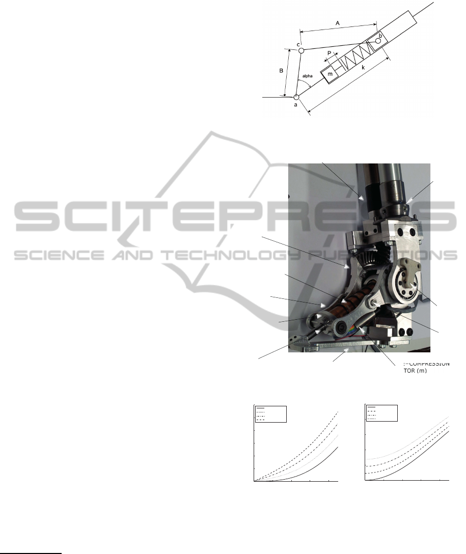
C
Figure 1: Configuration of a MACCEPA using rigid link-
ages. Compare to Figure 2
PRE COMPRESSION
MO
FOOT LINK
SHANK
LINK
GEAR HEAD
BLDC MOTOR +
MOMENT ARM
(B)
SPRING (k)
BAR (A)
CONNECTING
SLIDER
SLIDER (b)
ANKLE
JOINT
MACCEPA
JOINT
(c)
(a)
SLIDER BAR (B)
AN
JO
MA
JO
Figure 2: Implementation of the MACCEPA actuator.
0 10 20 30 40
0
100
200
300
400
500
600
alpha (deg)
torque (Nm)
P=0.0 mm
P=10.0 mm
P=20.0 mm
P=30.0 mm
(a)
0 10 20 30 40
0
5
10
15
20
25
alpha (deg)
stiffness (Nm/deg)
P=0.0 mm
P=10.0 mm
P=20.0 mm
P=30.0 mm
(b)
Figure 3: Torque and stiffness of the MACCEPA-design.
the entire normal joint torque and higher than previ-
ous designs by a factor of two.
The required motor power necessary to follow the
desired torque trajectory was calculated by first iden-
tifying the required position of the moment arm, at
every moment in time over a single step. The desired
torque trajectory was determined from biomechanical
data of healthy gait (Winter, D.A., 2005).
From the desired moment arm angle trajectory, the
Ankle-KneeProsthesiswithPoweredAnkleandEnergyTransfer-DevelopmentoftheCYBERLEGsAlpha-Prototype
225
desired moment arm velocity and power can be calcu-
lated. The spring constant and the pretension length
were optimized to minimize peak actuator power, the
main limiting factor in the size of the motor. Increas-
ing the pretension length increases the peak power
but the increased stiffness also greatly reduces the re-
quired motor velocity. The power, torque, and posi-
tion characteristics required to track the typical bio-
logical ankle torque with the MACCEPA actuator are
shown in Figure 4.
0 10 20 30 40 50 60 70 80 90 100
−200
0
200
400
Motor Power (W)
Power @ 1 step/sec (W)
Ankle Power
Motor Power
0 10 20 30 40 50 60 70 80 90 100
−50
0
50
100
150
Joint Torque
Torque (Nm)
Ankle Torque
MACCEPA Torque
0 10 20 30 40 50 60 70 80 90 100
−30
−20
−10
0
10
Moment Arm Angle (deg)
Stride (%)
Angle (deg)
Ankle Angle
Moment Arm Angle
Figure 4: Power, torque and position characteristics of the
MACCEPA actuator.
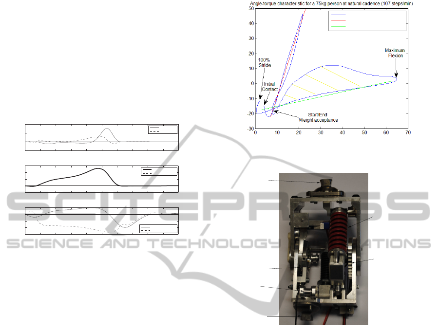
2.2 Knee
Knee behavior can be subdivided in two parts: first
the weight acceptance phase, characterized by a high
joint stiffness, and the flexion phase, where there is a
high knee flexion of about 60
◦
and a lowtorque to pre-
vent the leg from extension during swing phase. The
knee behavior can roughly be approximated by using
two springs placed between the lower leg and the up-
per leg, shown by the red and green lines in Figure 5,
respectively. A ratchet and pawl mechanism unlocks
the stiff spring used for the weight acceptance so the
knee can flex and provide sufficient ground clearance
for the swing phase.
Joint torque approximation is not accurate with
the combination of these two springs alone. Between
the end of the weight acceptance and maximum flex-
ion, a higher torque is needed around the knee joint to
prevent the knee joint from collapsing during the push
off phase. At this point, a second locking mechanism
locks in another stiff spring, placed between the knee
and the ankle. This energy transfer mechanism pro-
vides the necessary stiffness at the knee and, because
it is also connected to the ankle, transfers stored en-
ergy to the ankle where it can be used for push-off.
The realized knee design can be found in Figure 6.
Knee angle (deg)
Knee torque (Nm)
Torsional spring ~ 0.3Nm/°
Torsional spring ~ 4.5Nm/°
Natural knee gait data
Figure 5: Approximation of the knee torques by using 2
springs.
WEIGHT ACCEPTANCE
RATCHET
ENERGY −TRANSFER
PULLEY
KNEE−ANKL E
ENERGY −TRANSFER
RATCHET
UPPER−L EG
PYRAMID ADAPTER
LOWER−LEG
PYRAMID ADAPTER
WEIGHT ACCEPTANCE
SPRING
Figure 6: Back view of the prosthetic knee with two locking
mechanisms. The baseline spring (blue) is on the front of
the knee and is seen to the left of the weight acceptance
spring (red).
2.3 Energy Transfer
During normal walking of an able-bodied person, a
knee joint primarily dissipates energy (Winter, D.A.,
2005) providing an opportunity to harvest this energy
for use during a different part of the gait cycle. There
are two times during the gait cycle which the knee
mechanism attempts to collect and deliver to the an-
kle. These times are at the end of swing phase and
during late pushoff, the combined energy of these two
periods is displayed in the yellow shaded section of
Figure 5.
Energy from the end of swing phase is captured
in the baseline spring on the front of the knee. Then
the coupling mechanism is locked during stance and
pushoff, providing a direct kinematic constraint be-
tween the knee and the ankle. This kinematic con-
straint allows the torque generated by the baseline
spring and the ankle-knee kinematic constraint to
effectively transfer energy to the ankle at the end
NEUROTECHNIX2013-InternationalCongressonNeurotechnology,ElectronicsandInformatics
226

0 20 40 60 80 100
−100
−50
0
50
100
150
Stride (%)
Power @ 1 step/sec (W)
Motor Power (W)
Figure 7: Motor power required to match the average an-
kle torque with (red line) and without (black line) energy
transfer from the knee.
of pushoff. Transferred energy is delivered with a
slightly delayed ankle push-off when compared to
normal gait in order to transfer maximum energy.
Because this energy is now provided at the moment
where the ankle torque is the highest, there is a reduc-
tion in torque that the ankle actuator must provide.
In Figure 7, the reduction in motor power due to the
energy transfer mechanism required to match the av-
erage ankle torque is illustrated. The power peaks are
lower and there is an overall drop in energy usage of
about 30 % (7 J reduction compared to a total con-
sumption of 22 J per step).
2.4 Control System
The control system runs on a real-time controller,
a cRIO 9082 (National Instruments, Austin, Texas,
US), endowed with a 1.33 GHz dual-core proces-
sor running a NI real-time operating system and a
Field Programmable Gate Array (FPGA) processor
Spartan-6 LX150. Ankle motors is controlled by
means of commercial servos (Maxon EPOS2 70/10).
A closed-loop PI controller is used to control the
MACCEPA moment arm position. Control of the ref-
erence signal for the MACCEPA as well as for the
locking-unlocking mechanisms is based on the esti-
mates of the vertical ground reaction force and coor-
dinates of the center of pressure gathered by means of
two 64-channel pressure-sensitive insoles embedded
into the sport shoes worn by the amputee (Donati, M.
et al., 2013). This initial finite state machine control
system is intended to only provide basic capabilities
for testing purposes and will be later replaced by a
novel hybrid control system based motor primitives
and feedback reflexes.
3 RESULTS
Preliminary testing with both intact and amputated
limbs has proven successful. The prosthesis is cur-
rently undergoing a larger amputee trial, with results
from these trials in the near future. Multiple control
schemes translating the user motion intentions into
motor commands for the prosthesis are being tested to
incorporate the prosthesis within the larger CYBER-
LEGs framework.
As an initial study, we created a finite state ma-
chine using the input of the insole sensors to trigger
gait state transitions. A sample dataset from an am-
putee subject can be found in Figure 8. Here we can
see the gait state determined by the insoles as well as
the desired and actual MACCEPA moment arm posi-
tions. Note that during these early trials the moment
arm position was commanded to half of the full range
of torque required by the ankle during normal gait.
Even with these low ankle torques, we were able to
achieve reasonable ankle and knee kinematics during
the trials, and show a positive injection of energy at
the ankle joint. In addition, the motor/gearbox com-
bination used in these tests were much slower than
the initial design suggested so that integration into the
larger CYBERLEGs system could be expedited. This
highly limits the moment arm velocity, although for
these tests it did not prove to be a large issue, but must
be addressed in the future.
117 118 119 120 121 122 123
−1
0
1
2
State Information
Gait State: 0 = Swing, 1 = Late Stance, 2 = Early Stance
Weight Acceptance State: 0 = Unlocked, 1 = Locked
117 118 119 120 121 122 123
−20
0
20
Moment Arm Angle
Desired Moment Arm Angle
117 118 119 120 121 122 123
−20
0
20
40
Ankle Angle
117 118 119 120 121 122 123
−50
0
50
Knee Angle
Time (s)
Figure 8: Preliminary datatset from the first prosthesis tri-
als. Use of an early finite state machine with a conservative
moment arm position with low torque.
4 DISCUSSION
A new transfemoral active ankle-knee prosthesis with
energy transfer from the knee to the ankle has been
presented. The device combines a novel ankle actua-
tion design as well as a new knee-ankle energy trans-
fer mechanism with the intention of reducing the ener-
getic cost of both the user and the prosthesis. The cur-
rent control system incorporates the use of pressure-
sensitive foot insoles to determine the state of the gait
Ankle-KneeProsthesiswithPoweredAnkleandEnergyTransfer-DevelopmentoftheCYBERLEGsAlpha-Prototype
227

cycle on-line and control the knee and ankle modules,
as well as their mechanical coupling. Recorded data
and feedback from both healthy and amputated sub-
jects showed promising performance and encourage a
more extensive experimental characterization includ-
ing the effect of pretension on the energetics of the
gait cycle and the effects of the energy transfer mech-
anism. A powered knee based on the passive mecha-
nism of this design is currently in development. This
will allow sit to stand and stair climbing operations in
addition to efficient walking.
ACKNOWLEDGEMENTS
This work has been funded by the European Commis-
sions 7th Framework Program as part of the project
CYBERLEGs under grant no. 287894. The second
author is funded by a Ph.D. grant of the Agency for
Innovation by Science and Technology in Flanders
(IWT).
REFERENCES
Au, S., Berniker, M., and Herr, H. (2008). Powered ankle-
foot prosthesis to assist level-ground and stair-descent
gaits. Neural Networks, 21(4):654–66.
Au, S. and Herr, H. (2008). Powered ankle-foot prosthesis.
IEEE Robotics & Automation Magazine, 15(3):52–59.
Bellman, R., Holgate, M., and Sugar, T. (2008). SPARKy 3:
Design of an active robotic ankle prosthesis with two
actuated degrees of freedom using regenerative kinet-
ics. IEEE RAS & EMBS, pages 511–516.
Cherelle, P., Matthys, A., and et al. (2012). The AMP-Foot
2.0: Mimicking Intact Ankle Behavior with a Powered
Transtibial Prosthesis. In IEEE International Confer-
ence on Biomedical Robotics and Biomechatronics.
Donati, M. et al. (2013). A flexible sensor technology for
the distributed measurement of interaction pressure.
Sensors, 13(1):1021–1045.
Herr, H. M. and Grabowski, A. M. (2012). Bionic ankle-
foot prosthesis normalizes walking gait for persons
with leg amputation. Proc. Roy. Soc. Lon. B, 279:457–
464.
Hitt, J. K., Bellman, R., and et al. (2007). The SPARKy
Spring Ankle with Regenerative Kinetics project: De-
sign and analysis of a robotic transtibial prosthesis
with regenerative kinetics. In ASME IDETC/CIE, Las
Vegas, Nevada, USA, pages 1587–1596.
Hollander, K. W., Ilg, R., Sugar, T. G., and Herring, D.
(2006). An efficient robotic tendon for gait assistance.
Journal of biomechanical engineering, 128(5):788–
91.
IWalk (2013). Biom. http://www.iwalk.com/.
Kaufman, K. R., Levine, J. A., and et al. (2008). Energy Ex-
penditure and Activity of Transfemoral Amputees Us-
ing Mechanical and Microprocessor-Controlled Pros-
thetic Knees. Archives of Physical Medicine and Re-
habilitation, 89(July):1380–1385.
Matthys, A., Cherelle, P., Van Damme, M., Vanderborght,
B., and Lefeber, D. (2012). Concept and design of the
HEKTA (Harvest Energy from the Knee and Trans-
fer it to the Ankle) transfemoral prosthesis. In IEEE
International Conference on Biomedical Robotics and
Biomechatronics.
Ossur (2013). Power knee. www.ossur.com.
Sup, F., Bohara, A., and Goldfarb, M. (2008). Design and
Control of a Powered Transfemoral Prosthesis. In-
ternational Journal of Robotics Research, 27(2):263–
273.
Unal, R., Behrens, S. M., Carloni, R., Hekman, E. E. G.,
Stramigioli, S., and Koopman, H. F. J. M. (2010). Pro-
totype Design and Realization of an Innovative En-
ergy Efficient Transfemoral Prosthesis. In IEEE RAS
& EMBS.
Van Ham, R., Vanderborght, B., van Damme, M., Verrelst,
B., and Lefeber, D. (2007). MACCEPA, the mechan-
ically adjustable compliance and controllable equilib-
rium position actuator: Design and implementation in
a biped robot. Robotics and Autonomous Systems, 55
(10):761–768.
Vanderborght, B., Bicchi, A., and et al. (2013). Variable
Impedance Actuators : a Review. Robotics and Au-
tonomous Systems, (Accepted June 2013):1–39.
Villalpando, E. C. M., Weber, J., and etal. (2008). Design of
an Agonist-Antagonist Active Knee Prosthesis. IEEE
RAS & EMBS, pages 529–534.
Winter, D.A. (2005). Biomechanics and Motor Control
of Human Movement. John Wiley and Sons, United
States of America.
NEUROTECHNIX2013-InternationalCongressonNeurotechnology,ElectronicsandInformatics
228
