
DEVELOPMENT OF MICROWAVE BROADBAND FULL-MIMO
CHANNEL SOUNDER
For the Super High Bit-Rate Mobile Communication Systems
Jun-ichi Takada, Minseok Kim, Yuyuan Chang, Yohei Konishi
Graduate School of Science and Engineering, Tokyo Institute of Technology,
Box S6-4, 2-12-1 O-okayama, Meguro-ku, Tokyo 152-8550, Japan
takada@ide.titech.ac.jp, mskim@ide.titech.ac.jp, chang@ap.ide.titech.ac.jp, konishi@ap.ide.titech.ac.jp
Keywords: Full MIMO channel sounder, microwave mobile communication
Abstract: The paper summarizes four year activities and outcomes of development of full MIMO 24x24 channel
sounder operating at 11 GHz with the bandwidth of 400 MHz, for the development of microwave frequency
for the super high bit-rate mobile communications. The back ground motivation, design criteria, technical
challenges and significant results are presented. Since the development of the channel sounder was the
project goal, the detailed analyses of the double directional channels are left for future study.
1 INTRODUCTION
The rapid growth of the mobile data traffic demands
the super high bit-rate systems in near future, i.e.
more than 10 Gb/s/base station (BS). To realize
such a high bit-rate transmission, the bandwidth well
exceeding 100 MHz is required. Suzuki, Suyama
and Fukawa (2010) estimated that 24x24 MIMO
transmission with 400 MHz bandwidth can achieve
30 Gb/s/BS by deploying 64QAM and coding rate of
3/4 with overhead efficiency of 70%. Such wide
bandwidth is not at all available below 6 GHz,
which is believed to be the upper frequency limit for
the mobile or personal wireless access. Therefore,
the development of higher microwave frequency for
the mobile communications is crucial. Such high
frequency has been avoided for the mobile
communications, because of the strong shadowing
and large path loss. However, hybrid spectrum
techniques such as carrier aggregation or separation
of control and traffic channels have been recognized
as promising techniques to resolve the problem.
Low frequency narrowband channel is used to keep
the link for control and base traffic, while high
frequency wideband channel is opportunistically
used for high bit-rate traffic.
NTT Docomo, Tohoku University and Tokyo
Institute of Technology conducted the research
project on super high-bit rate mobile communication
systems for 4 years from 2009 until 2013 targetting
30 Gb/s/BS transmission. 11 GHz has been
identified due to the availability of the spectrum for
the test license with the bandwidth of 400 MHz. In
collaboration with the transmission technology team,
the authors have developed 24x24 channel sounder
with full MIMO software radio architecture.
The paper summarizes the design criteria,
technical challenges, and the outcomes in the
development of MIMO channel sounder.
2 DESIGN CRITERIA AND
TECHNICAL CHALLENGES
Full MIMO architecture is chosen for sharing the
limited hardware resources for channel sounding and
transmission test. The typical MIMO channel
sounders are implemented with SISO RF chain with
antenna multiplexers (e.g. MEDAV, n.a.). They
have the advantages of the cost and simplicity of
calibration. However, full MIMO architecture has
an obvious advantage of the flexibility of multilink
measurement by introducing the modular
architecture. In contrast, simple combination of
MIMO channel sounders is not so straightforward
for the practical measurements (Kolmonen et al.,
2010).
39
Takada J., Kim M., Chang Y. and Konishi Y.
DEVELOPMENT OF MICROWAVE BROADBAND FULL-MIMO CHANNEL SOUNDERFor the Super High Bit-Rate Mobile Communication Systems.
DOI: 10.5220/0004784900390042
In Proceedings of the Second International Conference on Telecommunications and Remote Sensing (ICTRS 2013), pages 39-42
ISBN: 978-989-8565-57-0
Copyright
c
2013 by SCITEPRESS – Science and Technology Publications, Lda. All rights reser ved
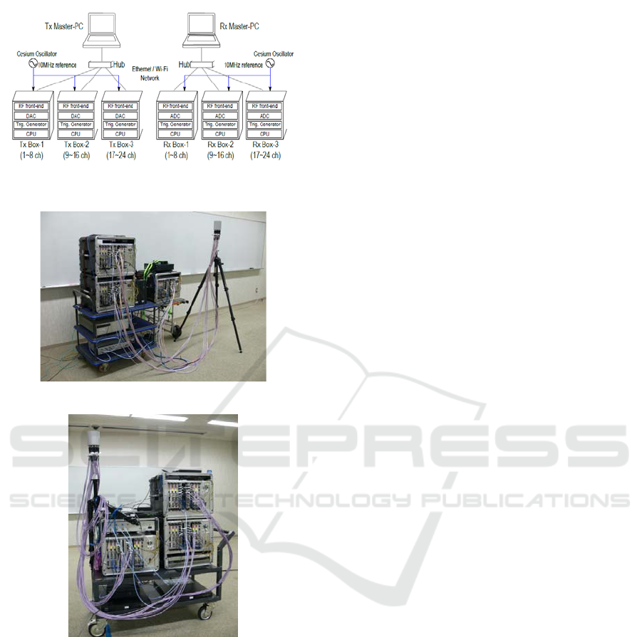
Figure 1: Scalable full MIMO channel sounder
architecture.
(a) Receiver
(b) Transmitter
Figure 2: MIMO channel sounder.
2.1 Synchronization
In the developed channel sounder, one transmitter or
receiver module consists of 8 RF channels, and three
modules can be integrated for directional
measurement, or be separated for multilink MIMO
measurement. They are synchronized by the
common or separated atomic oscillators. It is noted
that the absolute synchronization of frequency and
phase between transmitters and receivers is a
specific requirement for channel sounder, although
the hardware architectures are common for sounding
and transmission. It is found that rubidium
oscillators, which are commonly used as 10 MHz
references for synchronization between transmitter
and receiver, can not be stable enough when up-
converted to 11 GHz. Therefore, the cesium
oscillators are used instead. In addition to the
frequency synchronization, the clock phase
synchronization is necessary. The mechanism is
implemented to adjust the clock phases of
transmitter and receiver during back-to-back
calibration between transmitter and t receiver.
2.2 Signal Format
Due to the simultaneous transmission, multiplexing
technology is needed. Although any kind of
orthogonal signals can be used for multiplexing, the
authors chose unmodulated multitone signals and
hybrid FDM-STDM technique suitable for scalable
modular structure (Kim, Takada and Konishi, 2012).
Newman phase multitone (Boyd, 1986), which is
almost equivalent to chirp signal, has been used as
the wideband signal. Multitone signal has the
advantage of efficient spectrum usage for high delay
resolution. 4 channels are multiplexed in frequency
domain (FDM) (Sakaguchi, Takada and Araki,
2002), i.e. 1 module consists of 2 units. 6 units,
each of which consists of these 4 channels, are then
weighed with orthonormal vectors sequentially to
change the spatial pattern of the channel response
(STDM). STDM has the obvious advantage over
conventional TDM, since all the transmitter ports
always transmit the signals to maximize the
transmission power by using relatively low power
transmitters.
2.3 Antennas
Three types of array antennas are developed.
Directional measurement antenna is a uniform
circular array of 12-element dual polarization
antennas with 0.44 wavelength spacing. For the
high resolution parameter estimation, spherical
complex pattern has been measured discretely within
the limited range of the scanning, and the continuous
patterns for whole sphere are analytically
reconstructed by using the spherical wave functions
(Miao and Takada, 2013).
Two MIMO capacity measurement antennas are
both uniform linear arrays of 12-element dual
polarization antennas. Two different types of the
antenna elements are used, i.e. omnidirectional and
60 deg sector patterns in horizontal direction.
Second International Conference on Telecommunications and Remote Sensing
40

Antenna spacing can be flexibly controlled, but
should be more than one wavelength due to the large
size of the horizontal polarization antenna elements.
2.4 Calibration Procedure
To calibrate the whole MIMO system, the following
complicated calibration process is needed whenever
the units are turned on (Chang, Konishi, Kim and
Takada, 2012):
1. Baseband calibration to match all the channels
of DACs and ADCs (Pham, Kim and Takada,
2012)
Following calibration processes are manually
conducted by adjusting on-board variable
registers of delay chips, as the calibration
parameters do not change for long time.
(a) Phase and DC offsets of DACs are
calibrated by connecting DAC to
oscilloscope.
(b) Phase and DC offsets of ADCs are
calibrated by connecting ADC to DAC.
2. RF calibration to compensate IQ imbalance
and to suppress carrier leakage (Kim, Konishi,
Takada and Gao, 2012, Kim, Maruichi and
Takada, 2013)
As PLL synthesizers are reset whenever the
power is turned on, the automatic calibration
program has been developed.
(a) Transmitter IQ imbalance and carrier
leakage are compensated by digital
predistortion.
(b) They are calibrated by connecting DAC
to Tx input and spectrum analyzer to Tx
output. IQ imbalance is calibrated first,
and carrier leakage next.
(c) Receiver IQ imbalance and carrier
leakage are calibrated in digital domain
by connecting whole baseband and RF
chain.
3. Back-to-back calibration for transfer function
(Chang, Konishi, Kim and Takada, 2012)
(a) 8x8 calibration circuit has been
developed for module-wise back-to-back
calibration. 1 out of 8 transmitter ports is
selected by RF switch for feeding, while
8-port power divider feed all 8 receiver
ports simultaneously. For 24x24
calibration, reference pair of transmitter
and receiver modules are selected, and
other modules are calibrated against these
modules. S-parameters of calibration
circuit itself are compensated finally.
3 SPECIFICATION OF
CHANNEL SOUNDER
The channel sounder is originally designed to
operate in macrocellular and indoor environment
(Konishi, Kim, Chang and Takada, 2013).
The channel sounder is operating at the center
frequency of 11 GHz with the bandwidth of 400
MHz. Output power of the transmitter is 10 dBm
per channel, and the total transmission power is
about 24 dBm with 24 transmitter ports.
Special frame format is introduced to transmit
the sounding signal and the data stream
simultaneously, 4 μs guard interval is inserted into
each FDM symbol, which limits the maximum delay
spread although 2048 tones are introduced within
400 MHz band. The delay resolution of 2.5 ns is
determined from the bandwidth of 400 MHz.
Measurement dynamic range is 55~110 dB in
terms of path loss, and the noise floor is dominated
by the thermal noise.
Angular resolution of uniform circular array is
about 37 degrees. However, ray optical propagation
model and maximum likelihood parameter
estimation technique (Fleury et al., 1999) are being
introduced to de-embed the antenna characteristics
from measured propagation channel.
4 FIELD MEASUREMENT
CAMPAIGN
Measurement campaign has already been conducted
in indoor, microcell and macrocell environments,
since the radio license was valid only during the
project period.
4.1 Indoor Measurements
Indoor measurements were conducted in the
corridor, meeting and lecture rooms, entrance lobby,
and hall within the campus of Tokyo Institute of
Technology. Point crowds of the interior of the
rooms were simultaneously measured by using laser
scanner, together with the fish eye images, so that
the propagation mechanism can be analyzed in more
detail.
Although the detailed data analyses are left for
future works, some preliminary works such as multi-
link channel characteristics in the hall (Konishi et
al., 2012), and path loss and delay spread of
corridor-to-room channel (Kim, Konishi, Chang and
Takada, 2013) are presented.
Development of Microwave Broadband Full-Mimo Channel Sounder
41

4.2 Outdoor Measurements
Outdoor measurements are conducted in macrocell
and street microcell environments, within Ishigaki
city, Okinawa. Ishigaki city is located in rather
remote island, and is populated with about 50,000
people. Measurements were done in urban and
residential areas.
Point crowds of the surfaces of the buildings
were simultaneously measured by using laser
scanner, as well as 3D image (Topcon, n.d.).
Although the detailed analyses are left for future
works, some preliminary works such as macrocell
line-of-sight path loss (Chang et al., 2013a) and
MIMO eigenvalues (Chang et al., 2013b) are
presented.
4 CONCLUSIONS
The paper presented the design criteria, technical
challenges, and the outcomes in the development of
24x24 full MIMO channel sounder operating at 11
GHz with 400 MHz bandwidth for the development
of future super high-bit rate mobile communications.
The development of the channel sounder itself was
quite successful, while the detailed analysis of the
measurement campaigns is still left for the future
work.
ACKNOWLEDGEMENTS
This work was supported by “The research and
development project for expansion of radio spectrum
resources” of The Ministry of Internal Affairs and
Communications, Japan.
REFERENCES
Boyd, S. 1986. Multitone signals with low crest factor
IEEE Transactions on Circuits and Systems, 33, 1018–
1022.
Chang, Y., Konishi, Y., Kim, M. and Takada, J. 2012.
Calibration Techniques for Fully Parallel 24 X 24
MIMO Sounder. In ISAP 2012, 2012 International
Symposium on Antennas and Propagation.
Chang, Y. et al., 2013a. Analysis of Field Measurement
with Wideband MIMO Sounder at 11 GHz Frequency.
IEICE Technical Report, 112(384), 167-172.
Chang, Y. et al., 2013b Results of Field Measurement with
Wideband MIMO Sounder at 11 GHz for Macrocell
Environments. IEICE Technical Report, 113(8), 7-12.
Fleury, B.H., et al. 1999. Channel Parameter Estimation in
Mobile Radio Environments Using the SAGE
Algorithm. IEEE Journal of Selected Areas in
Communications, 17, 434-450.
Kim, M., Konishi, Y., Chang, Y. and Takada, J. 2013.
Characterization and Modeling of Indoor Wideband
MIMO Channels At 11 GHz. In EuCAP 2013, 7th
European Conference on Antennas and Propagation.
Kim, M., Konishi, Y., Takada, J. and Gao, B. 2012.
Automatic IQ Imbalance Compensation Technique for
Quadrature Modulator by Single-Tone Testing. IEICE
Transactions on Communications, E95-B, 1864-1868.
Kim, M., Maruichi, Y. and Takada, J. 2013. Parametric
Method of Frequency-dependent I/Q Imbalance
Compensation for Wideband Quadrature Modulator.
IEEE Transactions on Microwave Theory and
Techniques, 61, 270-280.
Kim, M., Takada, J. and Konishi, Y. 2012. A Novel
Scalable MIMO Channel Sounding Technique and
Measurement Accuracy Evaluation with Transceiver
Impairments. IEEE Transactions on Instrumentation
and Measurements, 61, 3185-3197.
Kolmonen V. et al. 2010, A Dynamic Dual-Link
Wideband MIMO Channel Sounder for 5.3 GHz.
IEEE Transactions on Instrumentation and
Measurements, 59, 873-833.
Konishi, Y. et al. 2012. Multi-link Indoor MIMO
Measurements at 11 GHz using Scalable Wideband
Channel Sounder. In ISAP 2012, 2012 International
Symposium on Antennas and Propagation.
Konishi, Y., Kim, M., Chang, Y. and Takada, J. 2013,
Development of Versatile MIMO Channel Sounder for
Double Directional and Multi-link Channel
Characterizations at 11 GHz, in preparation to submit
to IEEE Transactions on Instrumentation and
Measurements.
MEDAV (n.a.), Channel Sounder. Retrieved April 27,
2013, from http://www.channelsounder.de/
Pham, V.H., Kim, M. and Takada, J. 2012. Effect of I/Q
Skew in Baseband to Wideband Channel Sounder. In
MISW 2012, 4th Multidisciplinary International
Student Workshop of Tokyo Institute of Technology.
Sakaguchi, K., Takada, J. and Araki, K. 2002. A novel
architecture for MIMO spatio-temporal channel
sounder. IEICE Transactions on Electronics, 85, 436–
441.
Suzuki, H., Suyama, S. and Fukawa, K. 2010. Research
Topics for Super High Bit-Rate Mobile
Communication Systems (in Japanese). In
Proceedings of IEICE Communication Society
Conference, B-5-51.
Topcon (n.d.). Mobile Mapping System IP-S2 Lite.
Retrieved April 27, 2013, from http://
www.topcon.co.jp/en/positioning/products/product/3d
scanner/ips2lite.html
Yang, M. and Takada, J. 2013. Antenna Pattern
Reconstruction by Spherical Vector Waves for
Spherical Antenna Measurement, in EMTS 2013,
2013 URSI International Symposium on
Electromagnetic Theory.
Second International Conference on Telecommunications and Remote Sensing
42
