PHOTONIC GENERATION OF TERAHERTZ WAVES
FOR COMMUNICATIONS AND SENSING
Tadao Nagatsuma
Graduate School of Engineering Science, Osaka University,
1-3 Machikaneyma, Toyonaka 560-8531, Japan
nagatuma@ee.es.osaka-u.ac.jp
Keywords: Terahertz, Photonics, signal generation, communication, sensing
Abstract: This paper describes how effectively the photonic signal generation schemes are employed to enhance the
performance of terahertz-wave systems such as wireless communication, spectroscopy, and tomographic
imaging.
1 INTRODUCTION
Research on exploring terahertz (THz) waves, which
cover the frequency range from 100 GHz to 10 THz,
have lately increased since the nature of these
electromagnetic waves is suited to spectroscopic
sensing as well as to ultra-broadband wireless
communications (Nagatsuma, 2009, 2011). One of
the obstacles to developing applications of THz
waves is a lack of solid-state signal sources.
For the generation of THz waves, photonic
techniques are considered to be superior to
conventional techniques based on electronic devices
with respect to wide frequency bandwidth,
tunability, and stability. Moreover, the use of optical
fiber cables enables us to distribute high-frequency
(RF) signals over long distances instead of metallic
transmission media such as coaxial cables and
hollow waveguides.
In this scheme, optical-to-electrical (O-E)
converters, or “photodiodes”, which operate at long
optical wavelengths (1.3-1.55 μm), play a key role,
and high output current is required in addition to
large bandwidth for practical applications. Recent
progress of high-power photodiode technology has
accelerated the development of THz-wave system
applications (Nagatsuma et al., 2009).
In this paper, we will describe how the photonics
technologies are employed in THz-wave systems,
showing some of our recent applications, in
particular based on based on “continuous wave
(CW)” signals, such as wireless communications,
spectroscopy and imaging.
Optical Signal
Source
(Pulse/CW)
Optical-
to-THz
Convertor
Antenna,
Lens,
Prism
Nonlinear Optical Material
Photoconductor
Photodiode
CW
CW (λ
1
, λ
2
)
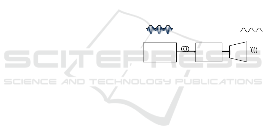
Figure 1: Schematic diagram of photonic continuous-wave
THz signal generation.
2 GENERATION AND
DETECTION OF CONTINUOUS
WAVES
In this section, we briefly review schemes for
photonic generation and detection of continuous-
wave (CW) THz waves.
2.1 Signal Generation
Figure 1 shows a schematic of CW THz-signal
generation based on optical-to-terahertz conversion.
First, intensity-modulated optical signals, whose
envelope is sinusoidal at a designated THz
frequency, are generated with use of light waves at
different wavelengths, λ
1
and λ
2
. Then, these two-
wavelength of lights are injected to conversion
media such as nonlinear optical materials (EO),
photoconductors (PC), and photodiodes (PD), which
43
Nagatsuma T.
PHOTONIC GENERATION OF TERAHERTZ WAVES FOR COMMUNICATIONS AND SENSING.
DOI: 10.5220/0004785000430048
In Proceedings of the Second International Conference on Telecommunications and Remote Sensing (ICTRS 2013), pages 43-48
ISBN: 978-989-8565-57-0
Copyright
c
2013 by SCITEPRESS – Science and Technology Publications, Lda. All rights reserved
leads to the generation of THz waves at a frequency
given by
f
RF
= cΔλ/λ
2
(1)
where Δλ is a difference in wavelength of lights, and
c is a velocity of light. The converted signals are
finally radiated into free space by an antenna, a lens,
etc.
Laser Diode
DC
Laser Diode
DC
Coupler
(Combiner)
λ
1
(f
1
)
λ
2
(f
2
)
f
1
-f
2
Wavelength
λ
λ
2
λ
1
t
Wavelength
λ
f
0
Nf
0
Wavelength
λ
Optical Frequency
Comb Generator
f
0
RF
λ
Optical
Filter
(a)
(b)
f
Wavelength
λ
f
Wavelength
λ
Optical Noise Source
(ASE Noise)
f
Optical
Filter
λ
Δ
f
Δ
f
Optical
Filter
Δ
f
(c)
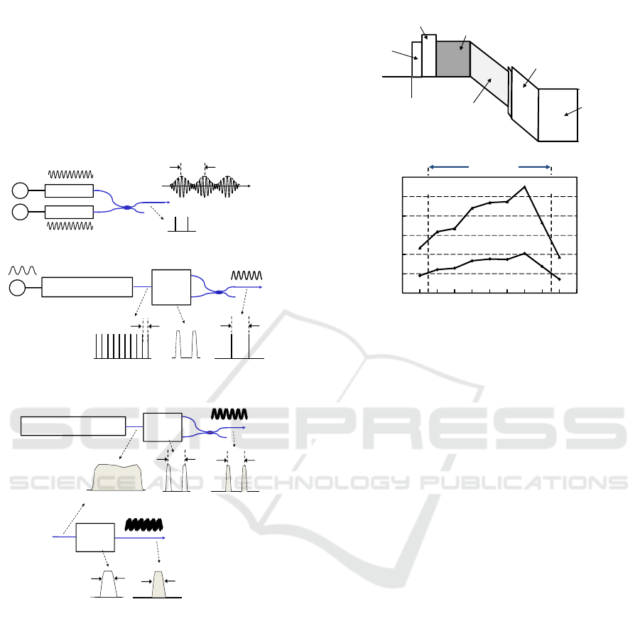
Figure 2: Schematic diagram of optical signal sources.
Typical optical signal sources are depicted in
Figs. 2(a) and 2(b); an optical heterodyning
technique using two frequency-tunable laser diodes,
and using the combination of an optical frequency
comb generator and filters, respectively. In the latter
case, two wavelength lights are filtered from the
optical filters, and this offers us with both wide-
band frequency tunability and excellent stability.
When so narrow linewidth or frequency resolution in
the spectroscopy and/or imaging is not required, we
can use two wavelength light filtered from the
optical noise source such as ASE noise in optical
amplifiers as shown in Fig. 2(c).
p-doped
Absorption Layer
Un-doped
Collection
Layer
n-contact
Layer
p-contact
Layer
Diffusion Block Layer
(C.B.)
(V.B.)
Un-doped
Absorption Layer
(a)
0
20
40
60
80
100
120
260 300 340 380 420
6 mA
10 mA
Frequency (GHz)
Detected Power (μW)
140 GHz
270
410
(b)
Figure 3: (a) Block diagram of the modified UTC-PD. (b)
Output power characteristics.
Among above-memtioned three types of optical-
to-electrical conversion media, the photodiode is
highly advantageous with respect the conversion
efficiency. In addition to the operation at long
optical wavelengths (1.3-1.55 μm), large bandwidth
and high output current are required for practical
applications. Among various types of long-
wavelength photodiode technologies, a uni-
traveling-carrier photodiode (UTC-PD) and its
derivatives have exhibited the highest output powers
at frequencies from 100 GHz to 1 THz, with
improvement in layer and device structures
(Nagatsuma et al., 2009).
Figure 3(a) shows the band diagram of the
photodiode optimized for the operation at 300-400
GHz, which is a modification of the UTC-PD. The
photodiode chip was packaged into the module with
a rectangular waveguide (WR-3) output port
(Wakatsuki et al., 2008). Figure 3(b) shows the
frequency dependence of the output power generated
from the module. The 3-dB bandwidth is 140 GHz
(from 270 to 410 GHz), which corresponds to the
maximum bit rate of 90 Gbit/s in the case of ASK
modulation. The peak output power was 110 μW at
380 GHz for a photocurrent of 10 mA with a bias
voltage of 1.1 V. The output power could be further
increased to over 500 μW by increasing the
photocurrent up to 20 mA with responsivity of 0.22
A/W.
Second International Conference on Telecommunications and Remote Sensing
44
To increase the output power to more than 1 mW,
one of the practical approaches is a power-
combining technique using an array of photodiodes.
With two photodiodes, the output power of >1 mW
has been obtained at the photocurrent of 18 mA per
photodiode at 300 GHz (Song et al., 2012).
At frequencies of over 300 GHz extending to 1
THz or higher, an antenna-integrated photodiode is
more efficient, and semi-spherical silicon lens is
often used to collimate a beam radiated from a
planar antenna such as bow-tie, log-periodic and
dipole antennas (Ito et al., 2005).
2.2 Signal Detection
As for detectors, there are several choices in the THz
regions, such as “direct detection” using Schottky
barrier diodes (SBDs) or bolometers and
“heterodyne detection” by combining mixers and
local oscillators (Fig. 4). There are electronic and
photonic mixers as well as electronic and photonic
local oscillators. We choose the best one depending
on required performance in each application.
Antenna
Diode
Bolometer
Antenna
Electronic
Mixer
LO Signal
Antenna
Electronic
Mixer
Antenna
(Lens)
Photonic
Mixer
Optical
LO Signal
SBD/Bolometer
SBD/SIS
PC/EO/PD
(a)
(b)
(c) (d)
O-E
Converter
Optical
LO Signal
SBD/Bolometer
Electrical (E)
Optical(O)
O
E
E
E
E
E, O
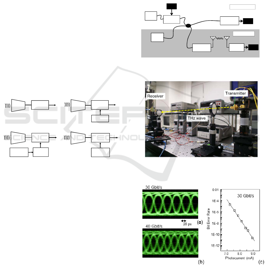
Figure 4: Configurations of THz detection system. O:
optical signal, E: electrical signal.
3 APPLICATIONS TO
COMMUNICATIONS AND
SENSING
In this section, we present our recent applications
based on based on CW THz signals, such as wireless
communications, spectroscopy and imaging.
3.1 Wireless Communication
Figure 5 illustrates an example of the application
schemes with photonics-based approach, showing
how the photonic RF signal generation can be
employed together with fiber-optic links (Kleine-
Ostmann and Nagatsuma, 2011; H.-J. Song and
Nagatsuma, 2011). In addition to the wired link
using the light wave at a wavelength of λ
1
, we can
transmit the same data with the wireless link by
introducing another wavelength (λ
2
) of light wave
and mixing the two wavelengths of light in the RF
photodiode. The photodiode generates RF signals,
whose frequency can be determined the difference in
the wavelength of the two light waves, which is
given by eq. (1).
Laser
(1)
Laser
(2)
Optical
Modulator
Fiber-optic Link
RF
Photodiode
RF
Receiver
Base-band
Photodiode
Data
λ
1
λ
2
f
RF
Data
Data
λ
1
+ λ
2
Wireless Link
λ
1
Figure 5: System concept of wired and wireless
convergence.
Figure 6: Photo of an experimemtal setup for the wireless
link.
Figure 7: Eye diagrams at 30 Gbit/s and 40 Gbit/s (b), and
bit error rate (BER) characteristics at 30 Gbit/s with a
carrier frequency of 300 GHz. Photocurrent (horizontal
axis of (c)) is proportional to the square root of the
transmitted power.
Photonic Generation of Terahertz Waves for Communications and Sensing
45
As for the receiver, we can use a simple diode
such as a Schottky-barrier diode (SBD) for the
demodulation based on the square-law detection in
the case of the ASK (OOK) data format. Thus, the
receiver becomes more cost-effective and energy-
efficient, if we can make use of a wide bandwidth
lying over the THz frequency region.
Figure 7 shows transmission characteristics at
300 GHz. For the generation of 300-GHz THz
waves, the wavelength difference in two lasers, Δλ,
was set to be 2.4 nm, and the optical signal is
converted to the RF (THz) signals by the UTC-PD.
THz waves are radiated from the horn antenna, and
dielectric lenses (2-inch diameter) are used to
collimate THz waves for both the transmitter and
receiver. The total antenna gain is about 40 dBi.
Transmission distance without significant decrease
in the received power was typically 0.5 – 1 m.
The performance limitation with respect to the
data rate is determined mainly by the bandwidth of
the UTC-PD in the transmitter and that of the SBD
detector in the receiver. The 3-dB bandwidth of the
UTC-PD is 140 GHz (from 270 to 410 GHz), which
corresponds to the maximum bit rate of 90 Gbit/s in
the case of ASK modulation. While the RF
bandwidth of the SBD detector also exceeds 100
GHz, IF (baseband) bandwidth for demodulated
signals in the receiver is about 20 GHz, which limits
the maximum bit rates. Figures 7(a) and 7(b) shows
eye diagrams demodulated by the receiver at 30
Gbit/s and 40 Gbit/s, respectively. From the bit error
rate (BER) characteristics, error-free (BER<10
-11
)
transmission has been achieved at 30 Gbit/s, which
is the highest data rate ever reported for “error-free”
wireless links.
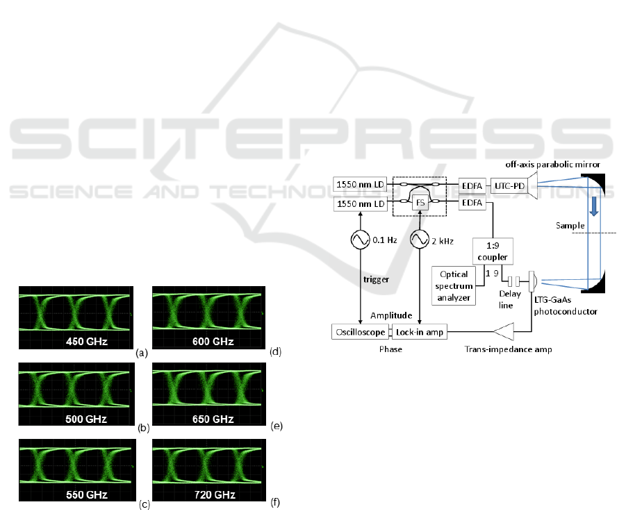
Figure 8: Eye diagrams at the 600-GHz band receiver
obtained by changing the carrier frequency or the optical
wavelength difference Δλ from 450 GHz to 720 GHz at a
bit rate of 1.6 Gbit/s.
Much larger bandwidth can be ensured when the
carrier frequency can be shifted higher. By using
antenna-integrated THz UTC-PD module (Ito et al.,
2005) together with the 600-GHz band SBD detector
(WR-1.5 waveguide), we have increased the
available bandwidth of more than 250 GHz with a
single transmitter/receiver pair. Figure 8 shows
received and demodulated waveforms at carrier
frequencies from 450 GHz to 720 GHz. Clear eye
diagrams at 1.6 Gbit/s has been obtained, which
show error-free transmission over the extremely
large bandwidth of 270 GHz.
3.2 Spectroscopy
Recently, THz spectroscopy systems based on CW
technology, which use monochromatic sources with
an accurate frequency control capability, have
attracted great interest (Hisatake et al., 2013). The
CW source-based systems, referred to as frequency-
domain spectroscopy (FDS), provide a higher signal-
to-noise ratio (SNR) and spectral resolution. When
the frequency band of interest is targeted for the
specific absorption line of the objects being tested,
FDS systems with the selected frequency-scan
length and resolution are more practical in terms of
data acquisition time as well as system cost.
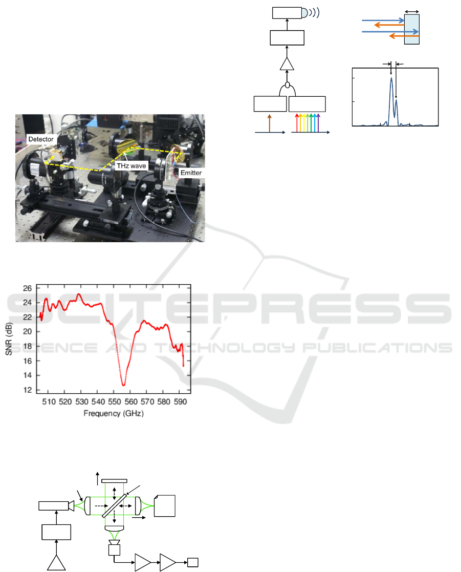
Figure 9: Experimental setup for the frequency-domain
spectroscopy. LD: laser diode, EDFA: Erbium-doped fiber
amplifier, FS: electro-optic frequency shifter.
THz-FDS system with photonic emitters and
detectors is frequently called a homodyne or self-
heterodyne system. Figure 9 shows a setup for the
THz-FDS system using the UTC-PD for the emitter
and a low-temperature-grown (LTG) GaAs
photoconductor for the detector. The optical
frequency/phase shifter (FS) enables us to accurately
measure both the amplitude and phase. Since two
Second International Conference on Telecommunications and Remote Sensing
46
laser diodes (LDs) are free-running, we monitor
each wavelength by the optical spectrum analyzer or
the wave meter. Figure 10 shows a photo of the
experimental setup for the spectroscpoy.
In order to check the frequency accuracy of the
system, we measured the absorption line of the water
vapor at 557 GHz as shown in Fig. 11. Currently, the
experimental standard deviation of the mean for the
absorption frequency is about 70 MHz.
Figure 10: Photo of an experimemtal setup for the
spectroscopy.
Figure 11: Measured absorption line of the water vapor at
557 GHz.
Optical
Amplifier
Optical
Modulator
UTC‐PD
PC
Object
Pre‐
Amplifier
Lock‐in‐
Amplifier
BeamSplitter
ReferenceMirror
Movable
Transmitter Receiver
SBD
Terah er tzWaves
Figure 12: Block diagram of the tomography system using
the broadband THz noise signals.
Optical
Amplifier
UTC-PD
Wavelength
Tunable Laser
Wavelength
Fixed Laser
A
B
Optical
Modulator
A
B
t
(a)
(b)
(c)
λ
0
λ
1
λ
2
t
Signal Power (a.u.)
0 5 10 15
Optical Path Length (mm)
Incident
Reflected
Figure 13: (a) Frequency-swept signal source. (b)
Reflection of THz waves at front-side (A) and back-side
(B). (c) Point spread function measured with the 600-GHz
band system showing the reflection points A and B of a
0.5-mm thick plastic plate.
3.3 Imaging
Figure 12 shows a block diagram of the tomographic
imaging system using a broadband terahertz noise
(incoherent signal) sources and a Mickelson
interferometer (Isogawa et al., 2012). This
configuration is similar to that of the optical
coherence tomography. The broadband noise signals
with sufficient power are generated by feeding the
amplified spontaneous emission (ASE) noise from
the Er-doped fiber amplifier to the photodiode.
In the setup, first, a THz wave travels to the
beam splitter after being collimated by a dielectric
lens. The beam splitter divides the THz wave into
two directions with a power ratio of 50/50. One goes
to the reference mirror and the other to an object
after being focused. Both reflected waves travel
back to the beam splitter again and go to the SBD as
a power detector. Finally, detected signals are
amplified by a preamplifier and a lock-in amplifier.
A personal computer (PC) controls positions of both
the reference mirror and the objective lens. The
noise bandwidth of 120 GHz centered at 350 GHz
determines the depth resolution of 1.2 mm (Isogawa
et al., 2012).
In place of the optical noise sources, the
combination of a fixed wavelength laser and a
wavelength tunable laser (Fig. 13(a)) enables us to
modify the tomography system from time-domain to
frequency-domain one (Ikeou et al., 2012). In this
scheme, depth-position information can be obtained
by Fourier-transforming the frequency-
(wavelength-) swept interference signals. Figure
Photonic Generation of Terahertz Waves for Communications and Sensing
47

13(c) shows the point spread function, which
corresponds to the position of the reflection points at
A (front-side) and B (back-side) for a plastic plate
with 0.5-mm thickness, when the 600-GHz band
system was used.
4 CONCLUSIONS
We have described system applications, which
efficiently take advantages of photonics-based ultra-
broadband signal generation techniques at over 100-
GHz frequencies. Use of optical fiber cables also
makes it easy to handle high-frequency signal
distribution or cabling in the instrumentation. These
features will not be replaced with electronic systems,
even though the operation frequency of electronic
devices is increasing up to the THz region.
ACKNOWLEDGEMENTS
The author wish to thank Drs H. -J. Song, K. Ajito,
N. Kukutsu, S. Kuwano, J. Terada, N. Yoshimoto,
and T. Ishibashi with NTT, S. Hisatake, M. Fujita, K.
S. Horiguchi, Y. Minamikata, T. Ikeou, H. Nishii
with Osaka University for their collaboration and
support. This work was supported in part by the
JST-ANR WITH program and by the Ministry of
Education, Science, Sports and Culture, Grant-in-
Aid for Scientific Research (A), 23246067, 2011.
REFERENCES
Hisatake, S., Kitahara, G., Ajito, K., Fukada, Y.,
Yoshimoto, N., Nagatsuma, T., 2013. Phase-sensitive
terahertz self-heterodyne system based on photodiode
and low-temperature-grown GaAs photoconductor at
1.55
μ
m. IEEE Sensors Journal, vol. 13, no. 1, pp.
31–36.
Ikeou, T., Isogawa, T., Ajito, K., Kukutsu, N., Nagatsuma,
T., 2012. Terahertz imaging using swept source
optical-coherence-tomography techniques. Tech. Dig.
IEEE Intern. Topical Meeting on Microwave
Photonics, Session 8, Noordwijk.
Ito, H., Furuta, T., Nakajima, F., Yoshino, K., Ishibashi,
T., 2005. Photonic generation of continuous THz
wave using uni-traveling-carrier photodiode. IEEE J.
Lightwave Tech., vol. 23, no. 12, pp. 4016–4021.
Isogawa, T., Kumashiro, T., Song, H.-J., Ajito, K.,
Kukutsu, N., Iwatsuki, K., Nagatsuma, T., 2012.
Tomographic imaging using photonically generated
low-coherence terahertz noise sources. IEEE Trans.
Terahertz Science and Tech., vol. 2, no. 5, pp. 485–
492.
Kleine-Ostmann, T., Nagatsuma, T., 2011. A review on
terahertz communications research. J. Infrared Milli.
Terhz. Waves, vol. 32, no. 2, pp. 143–171.
Nagatsuma, T, Ito, H., Ishibashi, T., 2009. High-power RF
photodiodes and their applications. Laser Photon.
Rev., vol. 3, no. 1-2, pp. 123–137.
Nagatsuma, T., 2009. Generating millimeter and terahertz
waves. IEEE Microwave Magazine, vol. 10, no. 4, pp.
64–74.
Nagatsuma, T., 2011. Terahertz technologies: present and
future, IEICE Electron. Express, vol. 8, no. 14, pp.
1127–1142.
Song, H.-J., Nagatsuma, T., 2011. Present and future of
terahertz communications. IEEE Trans. Terahertz
Science and Technology, vol.1, no. 1, 256–264.
Song, H.-J., Ajito, K., Muramoto, Y., Wakatsuki, A.,
Nagatsuma, T., Kukutsu N., 2012. Uni-travelling-
carrier photodiode module generating 300 GHz
power greater than 1 mW. IEEE Microwave and
Wireless Components Letters, vol. 22, no. 7, pp. 363–
365.
Wakatsuki, A., Furuta, T., Muramoto, Y., Yoshimatsu, T.,
Ito, H., 2008. High-power and broadband sub-
terahertz wave generation using a J-band photomixer
module with rectangular-waveguide output port.
Proc. Int. Conf. on Infrared, Millimeter, and
Terahertz Waves, pp. 1999-1–1999-2.
Second International Conference on Telecommunications and Remote Sensing
48
