
EXPERIMENTAL INVESTIGATION ON NONLINEAR
CHARACTERISTICS OF A HIGH-TEMPERATURE
SUPERCONDUCTING DUAL-BAND BANDPASS FILTER
Shoichi Narahashi
1
, Kei Satoh
1
, Yasunori Suzuki
1
, and Yuta Takagi
1
1
Research Laboratories, NTT DOCOMO, INC., 3-6 Hikari-no-oka, Yokosuka, Kanagawa, Japan
{narahashi, satokei, suzukiyasu, takagiyu}@nttdocomo.co.jp
Keywords: Dual-band, Bandpass Filter, Superconductor, Intermodulation Distortion, Third-order Intercept Point
Abstract: This paper presents an experimental investigation on the nonlinear characteristics of a high-temperature
superconducting (HTS) dual-band bandpass filter (DBPF) that has two passbands and comprises a coplanar-
waveguide quarter-wavelength resonator with odd- and even-mode resonant frequencies. An HTS filter is a
potential candidate for an RF multi-band bandpass filter (MBPF) that has multiple passbands, which will
support broadband transmission in future mobile communication systems. It is, however, indispensable to
elucidate the nonlinear characteristics of the HTS-MBPF because the nonlinearity of HTS materials causes
intermodulation distortion (IMD). This paper presents the IMD characteristics of a 2.0-/3.5-GHz band HTS-
DBPF using a YBCO thin film deposited on a MgO substrate when two tones with a 30-kHz separation are
individually and simultaneously input to each passband. Experimental investigations confirm that the HTS-
DBPF generates different third-order IMD characteristics depending on how the two tones are input to the
HTS-DBPF. This paper also presents a method for estimating the third-order IMD characteristics based on
the measurement results.
1 INTRODUCTION
In recent years, Carrier Aggregation (CA) has
attracted attention as a technology for improving
transmission speeds in future mobile communication
systems (Miki, Iwamura, Kishiyama, Anil & Ishii
2010). CA achieves broadband transmission using
several fundamental frequency blocks (referred to as
component carriers (CCs)) aggregately and
simultaneously. An RF filter with multiple
passbands, i.e., a multiband bandpass filter (MBPF),
is a basic circuit that is expected to achieve
broadband transmission such as CA using CCs in
different frequency bands.
As a key device for supporting CA, the MBPF is
required to have high performance such as sharp-
skirt characteristics at the band-edges and a high
degree of attenuation in the stopbands with low
insertion losses in the passbands, which is
remarkable when a wireless system with a high
transmitter power is assigned to the frequency band
between the two passbands of the MBPF. A high-
temperature superconducting (HTS) filter is a
potential candidate that satisfies these requirements
(Abu-Hudrouss, Jayyousi & Lancaster, 2008).
It is indispensable to investigate the nonlinear
characteristics of the HTS filter because
intermodulation distortion (IMD) is caused by the
nonlinear characteristics of the HTS materials when
applying the HTS filter to mobile communication
systems. To measure the nonlinear characteristics,
there are two common techniques (Wilker, Shen,
Pang, Holstein & Face, 1995): one is the IMD
measurement method using a signal with two tones
and the other is the single tone harmonic generation
measurement method. It is desirable to utilize the
IMD measurement method using a signal with two
closely-spaced tones in evaluating the nonlinear
characteristics of the HTS filter since it might
attenuate the power level of the harmonic
components of the single tone.
The authors have shown the IMD characteristics
of the 2.0-/3.5-GHz band HTS-DBPF with a YBCO
thin film deposited on a MgO substrate when two
signals are individually and simultaneously input to
the center of the lower passband and the center of
54
Narahashi S., Satoh K., Suzuki Y. and Takagi Y.
EXPERIMENTAL INVESTIGATION ON NONLINEAR CHARACTERISTICS OF A HIGH-TEMPERATURE SUPERCONDUCTING DUAL-BAND BANDPASS FILTER.
DOI: 10.5220/0004785200540057
In Proceedings of the Second International Conference on Telecommunications and Remote Sensing (ICTRS 2013), pages 54-57
ISBN: 978-989-8565-57-0
Copyright
c
2013 by SCITEPRESS – Science and Technology Publications, Lda. All rights reserved
higher passband as initial research on evaluating the
IMD characteristics of an MBPF (Satoh, Takagi,
Narahashi & Nojima, 2011; Satoh, Takagi &
Narahashi, 2012a; Satoh, Takagi, Narahashi &
Nojima, 2012b).
This paper presents an experimental
investigation on the IMD of the proposed 2.0-/3.5-
GHz band HTS-DBPF. Measurement results show
that the third-order IMD (IMD3) characteristics are
generated differently depending on how the two-
tone signal with a 30-kHz separation is input to the
HTS-DBPF. The two ways that the signal is input to
the HTS-DBPF are that the two-tone signals are
individually input to either the 2.0-GHz band or 3.5-
GHz band, or the two tone signals are
simultaneously input to both the 2.0-GHz band and
3.5-GHz band. This paper also presents a method for
estimating the IMD3 characteristics based on the
third-order polynomial approximation of the input-
output characteristics of the HTS-DBPF.
2 RESONATOR FOR HTS-DBPF
Figure 1 shows the resonator for the HTS-DBPF that
has odd- and even-mode resonant frequencies (Satoh
et al., 2011). These two resonant modes have
different current flows on the short stub.
This suggests that different current flows allow
not only independent configuration of the coupling
coefficients for the lower and higher passbands but
also suppression of the IMD when a signal is
simultaneously input to each passband.
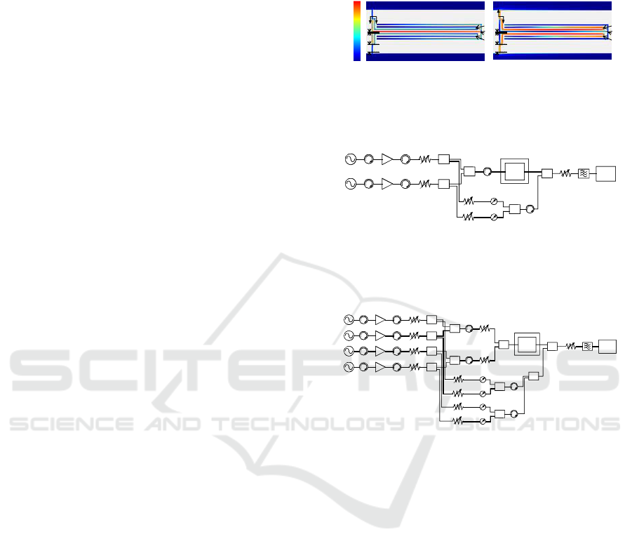
3 IMD MEASUREMENTS
3.1 Measurement System
Figure 2 shows a block diagram of a two-tone IMD
measurement system with a fundamental signal
cancellation circuit for a single-band bandpass filter
(Blount, Olson, Tshudy, Foote & Trantanella, 2004;
Futatsumori, Furuno, Hikage, Nojima, Akasegawa,
Nakanishi & Yamanaka, 2009). This measurement
system enables measurement of the IMD
characteristics without the nonlinear effect of the
spectrum analyzer because two fundamental signals
can be suppressed by more than 60 dB. By using the
fundamental signal cancellation circuit, the IMD
characteristics could be measured in detail at low
power levels.
Figure 3 shows a new block diagram of two
kinds of two-tone IMD measurement systems with a
fundamental signal cancellation circuit for each
High
Low
a
b
c
s
i
Odd
i
Even
d
a
b
c
s
d
(a) Odd-mode frequency (b) Even-mode frequency
Figure 1: Resonator structure and current density
distribution.
f
1
DUT
Power
amplifier
Isolator
Signal
generator
Cryostat
Variable
attenuator
Phase
shifter
Variable
attenuator
CouplerIsolatorIsolator
Coupler
Coupler
Coupler
Spectrum
analyzer
f
2
Variable
attenuator
Isolator
Filter
Figure 2: Block diagram for measuring IMD
characteristics of single-band bandpass filter.
f
1
DUT
Power
amplifier
Isolator
Signal
generator
Cryostat
Variable
attenuator
Phase
shifter
Variable
attenuator
CouplerIsolatorIsolator
Coupler
Coupler
Coupler
Spectrum
analyzer
f
2
Vari able
attenuator
Isolator
Filter
f
3
f
4
Vari able
attenuator
Coupler
Coupler
Figure 3: Block diagram for measuring IMD
characteristics of dual-band bandpass filter.
passband in order to evaluate nonlinear
characteristics when the two kinds of two-tone
fundamental signals are input to each passband of
the HTS-DBPF.
Figure 4 is a photograph of the configuration for
the IMD measurement. This measurement system
also enables measurement of the IMD characteristics
with a wide dynamic range.
3.2 Measured Results
Figure 5 shows the measured IMD characteristics of
the HTS-DBPF together with the ideal IMD3
characteristics. Here, the line with the slope of the
third order fitted to the measured results at each
passband represent the ideal IMD3 characteristics. In
Figure 5(a), blue and red squares represent the third-
order IMD (IMD3) characteristics for the 2.0-GHz
band and 3.5-GHz band of the HTS-DBPF when a
Experimental Investigation on Nonlinear Haracteristics of a High-Temperature Superconducting Dual-Band Bandpass Filter
55
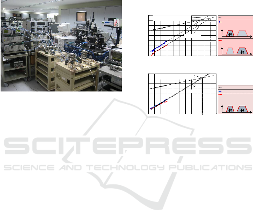
two-tone fundamental signal with the separation of
30-kHz is input to the 2.0-GHz and 3.5-GHz
passbands, respectively. The input and output power
per tone are represented on the horizontal and
Figure 4: Experimental configuration for IMD
measurement.
vertical axes, respectively. The measured IMD
characteristics nearly coincide with the ideal
distortion. The third-order input intercept point
(IIP3) for the 3.5-GHz passband is +50 dBm at 60
K, while the IIP3 for the 2.0-GHz passband is +43
dBm. If the same IMD is assumed for each
passband, the HTS-DBPF can handle an
approximately 2.9-times higher input signal power
in the 3.5-GHz passband than that in the 2.0-GHz
passband at 60 K.
Figure 5(b) shows the measured IMD3
characteristics for both passbands of the HTS-DPBF
when two kinds of two-tone fundamental signals
(1957.795- and 1957.825-MHz signals for the 2.0-
GHz passband, and 3463.515- and 3463.545-MHz
signals for the 3.5-GHz passband) are
simultaneously input to each passband. The total
input power to the HTS-DBPF in Figure 5(b) is 3 dB
higher than that in Figure 5(a). The IIP3 for the 3.5-
GHz passband is higher than that for the 2.0-GHz
passband. Based on Figure 5, the HTS-DBPF has
almost the same IIP3 of approximately +43 dBm in
the 2.0-GHz passband. If the same IMD is assumed
for each passband, the power level of the input
signal is defined by the IIP3 for the 2.0-GHz
passband.
3.3 IMD3 Estimation
As shown in Figure 5, the IMD3 characteristics are
generated differently depending on how the two-
tone signal is input to the HTS-DBPF. This section
estimates the IMD3 characteristics shown in Figure
5(b) based on the polynomial approximation of the
input-output characteristics of the HTS-DBPF.
If a two-tone signal with equal separation is
input to each passband of an MBPF that has n
passbands, the following two combinations represent
IMD3 in 3.5GHz band
when fundamental signals
are input to 3.5-GHz band
f
4
IMD3 in 2.0-GHz band
when fundamental signals
are input to 2.0-GHz band
f
2
Fundamental components
f
1
f
3
-100
-80
-60
-40
-20
0
20
40
60
0 5 10 15 20 25 30 35 40 45 50 55
O
u
t
p
u
t
P
o
w
e
r
(
d
B
m
)
Input Power (dBm)
IIP3 (2.0-GHz Band) = 43 dBm
IIP3 (3.5-GHz Band) = 50 dBm
Ideal IMD3
Ideal IMD3
(a) Each passband
IMD3 in 2.0-GHz band
IMD3 in 3.5-GHz band
when fundamental signals
are input to 2.0-and 3.5-
GHz bands
f
3
f
4
f
1
f
2
Fund amental components
-100
-80
-60
-40
-20
0
20
40
60
0 5 10 15 20 25 30 35 40 45 50 55
O
u
t
p
u
t
P
o
w
e
r
(
d
B
m
)
Input Power (dBm)
IIP3 (2.0-GHz band) = 43 dBm
IIP3 (3.5-GHz band) = 44 dBm
Ideal IMD3
(b) Both passbands
Figure 5: Measured IMD of HTS-DBPF using 30-kHz
separated signals at 60 K.
the frequency components of the IMD3
characteristics generated in the vicinity of the two-
tone signal at each passband.
()
12 21
112 2 21
(i) 2 , 2
(ii) ,
,1,,,
ii i i
ijj i j j
ij n i j
ω
ωωω
ω
ωω ωωω
−
−
+− +−
=≠"
(1)
where
ω
i1
and
ω
i2
(
ω
i1
<
ω
i2
) represent the angular
frequencies of the first and second tones at the i-th
passband, respectively. Here, the input signal, x
i
(t),
to the i-th passband is assumed to be defined as
(
)
(
)()
1112 22
cos cos
iiiii ii
xt a t a t
ωφ
ω
φ
=++ +
(2)
where a
i1
and a
i2
, and
φ
i1
and
φ
i2
represent the
amplitudes and phases of the two-tone signal,
respectively. Assuming that the input-output
characteristics of the HTS-MBPF can be expressed
by the third-order polynomial approximation, the
output signal, y
i
(t), of the i-th passband of the MBPF
is given as
(
)
(
)
(
)
3
13iiiii
yt bxt bxt=+
(3)
Second International Conference on Telecommunications and Remote Sensing
56

where parameters b
1i
and b
3i
are defined as the
coefficients of the first-order term and the third-
order term of x
i
(t) derived from the measured IMD3
characteristics when x
i
(t) is input to the i-th passband,
respectively. Then, the total output signal, y(t), of
the HTS-MBPF can be approximated as
-100
-80
-60
-40
-20
0
20
40
60
0 5 10 15 20 25 30 35 40 45 50 55
O
u
t
p
u
t
P
o
w
e
r
(
d
B
m
)
Input Power (dBm)
Calculated IMD3 (2 GHz)
Calculated IMD3 (3.5 GHz)
Measured IMD3 (2 GHz)
Measured IMD3 (3.5 GHz)
Measured fundamental components
Figure 6: Measured and calculated IMD3 for 2-GHz band
and 3.5-GHz band.
() () ()
3
1/3
13
11
.
nn
ii i i
ii
yt bx t b x t
==
⎛⎞
=+
⎜⎟
⎝⎠
∑∑
(4)
Figure 6 shows the measured and calculated
IMD3 characteristics for each passband as well as
the fundamental components of the HTS-DPBF
using Equation (4) and parameters b
1i
and b
3i
(i = 1,
2). Comparing Figure 5(a) to Figure 5(b) leads to the
fact that the IMD3 characteristics are almost the
same in the 2-GHz band whereas they are 15.1 dB
higher in the 3.5-GHz band at the input power level
of 5 dBm. This difference is calculated as 16.6 dB
using Eq. (4), which indicates good agreement
between the measured and calculated results. The
increase in the IMD3 characteristics in the 3.5-GHz
band is considered to be due to the following reason.
The IMD3 components generated by the
combination of angular frequency
ω
21
+
ω
11
-
ω
12
(which depends on parameter b
31
) appear at the
angular frequency of 2
ω
11
-
ω
12
since parameter b
31
is
4.9-times (13.7 dB) greater than parameter b
32
.
4 CONCLUSIONS
This paper presented an experimental investigation
on the IMD characteristics of an HTS-DBPF. A new
two-tone IMD measurement system enables the
evaluation of the IMD characteristics of the HTS-
DBPF when the HTS-DBPF simultaneously deals
with two kinds of two-tone fundamental signals.
This paper also presented a method for estimating
the IMD3 characteristics based on the third-order
polynomial approximation of the input-output
characteristics of the HTS-DBPF.
There still remain technical issues such as
clarifying the effective range of the HTS-DBPF
using widely-separated signals or a modulated signal,
investigating the nonlinearity of the HTS-DBPF
when interference signals are input to its passband
and when signals are input to its passband edges or
stopbands, and confirming whether or not the
proposed IMD3 estimation method is available when
the two-tone signal employs a frequency separation
other than 30 kHz.
REFERENCES
Miki, N., Iwamura, M., Kishiyama, Y., Anil, U., and Ishii,
H. 2010. CA for Bandwidth Extension in LTE-
Advanced. NTT DOCOMO Technical Journal, 12(2),
10-19.
Abu-Hudrouss, A. M., Jayyousi A. B., and Lancaster M. J.
2008. Triple-Band HTS Filter Using Dual Spiral
Resonators with Capacitive-Loading. IEEE Trans.
Appl. Supercond., 18(3), 1728-32.
Wilker, C., Shen, Z., Pang, P., Holstein, W. L., and Face,
D. W. 1995. Nonlinear Effects in High Temperature
Superconductors: 3
rd
Order Intercept from Harmonic
Generation. IEEE Trans. Appl. Supercond., 5(2),
1665-70.
Satoh, K., Takagi, Y., Narahashi, S., and Nojima, T. 2011.
Intermodulation Distortion Characteristics of High-
Temperature Superconducting Dual-Band Bandpass
Filter. Proc. of CJMW.
Satoh, K., Takagi, Y., and Narahashi, S. 2012a.
Experimental Investigation of the Intermodulation
Distortion Characteristics of High-Temperature
Superconducting Dual-Band Bandpass Filter. Proc. of
TJMW, FR4-6.
Satoh, K., Takagi, Y., Narahashi, S., and Nojima, T.
2012b. Experimental Investigation of the Relationship
between Operating Temperature and Power Handling
Capability of High-Temperature Superconducting
Dual-Band Bandpass Filter. Physics Procedia, 36, 13-
18.
Blount, P., Olson, M., Tshudy, R., Foote, D., and
Trantanella, C. 2004. An Automated Phase
Cancellation Method for Measuring Ultra-High Third
Order Intercept Points. IEEE MTT-S Int. Microwave
Symp. Dig., 1727-30.
Futatsumori, S., Furuno, M., Hikage, T., Nojima, T.,
Akasegawa, A., Nakanishi, T., and Yamanaka, K.
2009. Precise Measurement of IMD Behavior in 5-
GHz HTS Resonators and Evaluation of Nonlinear
Microwave Characteristics. IEEE Trans. Appl.
Supercond., 19(3), 3595-99.
Experimental Investigation on Nonlinear Haracteristics of a High-Temperature Superconducting Dual-Band Bandpass Filter
57
