
3D Object Recognition based on the Reference Point Ensemble
Toshiaki Ejima
1
, Shuichi Enokida
1
, Toshiyuki Kouno
2
, Hisashi Ideguchi
2
and Tomoyuki Horiuchi
2
1
Kyushu Institute of Technology, 680-4 Kawazu, Iizuka-shi, Fukuoka, Japan
2
YASKAWA Electric Corporation, 2-1 Kurosakishiroishi, Yahatanishi-ku, Kitakyushu 806-0004, Japan
Keywords:
Reference Point Ensemble, Mode Switching, L-Surflet-Pair, Bin Picking.
Abstract:
In the present paper, we have proposed a high-performance 3D recognition method based on the reference
point ensemble, which is a natural extension of the generalized Hough transform. The reference point ensem-
ble consists of several reference points, each of which is color-coded by green or red, where the red reference
points are used to verify the hypothesis, and the green reference points are used for Hough voting. The con-
figuration of the reference points in the reference point ensemble is designed depending on the model shape.
In the proposed method, a set of reference point ensembles is generated by the local features of a given 3D
scene. Each generated reference point ensemble is a hypothetical 3D pose of a given object in the scene. Hy-
potheses passing through the verification by the red reference points are used for Hough voting. Hough voting
is performed independently in each green point space, which reduces the voting space to three dimensions.
Although a six-dimensional voting space is generally needed for 3D recognition, in the proposed method, the
six-dimensional voting space is decomposed into a few three-dimensional spaces. This decomposition and the
verification using green or red reference points have been demonstrated experimentally to be effective for 3D
recognition. In other words, the effective recognition has been achieved by skillfully switching the following
two different modes. (A) Individual mode: Voting of the hypothesis independently in each green Hough space
and verifying of hypothesis with red reference points are done in this mode. (B) Ensemble mode : Verifying
of registration into PHL(promising hypothesis list) and aggregating of total votes are done in this mode. This
mode switching mechanism is the most significant characteristic of the proposed method.
1 INTRODUCTION
3D object recognition is core technology for use in
a bin picking system. Recently, 3D object recogni-
tion for complex scenes, such as irregularly arranged
homogeneous objects, has attracted a great deal of at-
tention. Robot vision that can function in real envi-
ronments is expected, and high-performancerobot vi-
sion is needed in order to develop intelligent robots
that will work on behalf of people in real environ-
ments.(Rusu, 2010) 3D object recognition methods
are generally classified into two types, depending on
the characteristics of the local feature used.
(I) 3D recognition using high-dimensional lo-
cal features: Recognition by constructing a
reliable correspondence between model and
scene.(Johnson and Hebert, 1999; Chua and
Jarvis, 1997; Mian et al., 2006; Sun et al., 2003;
Tombari et al., 2010; Mian et al., 2010; Rusu
et al., 2009)
(II) 3D recognition using several simple local
features and their combination: Recognition
by generating several hypotheses (poses) us-
ing the majority rule (by Hough transforma-
tion).(Rabbani and Heuvel, 2005; Tombari and
Stefano, 2010; Drost et al., 2010; Kim and
Medioni, 2011)
Type I features are composed of key points and
descriptors. Spin Image (Johnson and Hebert, 1999),
Point fingerprint (Tombari et al., 2010), and SHOT
(Mian et al., 2010) have been proposed for using
Type I features. Each of these features is a high-
dimensional feature derived from 3D points of ob-
jects. After establishing the correspondences between
the model and the scene by matching features of the
model, a plurality of correspondences with high re-
liability are used for 3D recognition. This approach
is excellent in terms of efficiency because recognition
is possible using only a few correspondences of the
local feature. On the other hand, there is a need to
261
Ejima T., Enokida S., Kouno T., Ideguchi H. and Horiuchi T..
3D Object Recognition based on the Reference Point Ensemble.
DOI: 10.5220/0004651802610269
In Proceedings of the 9th International Conference on Computer Vision Theory and Applications (VISAPP-2014), pages 261-269
ISBN: 978-989-758-009-3
Copyright
c
2014 SCITEPRESS (Science and Technology Publications, Lda.)

ensure robustness with respect to background noise,
such as occlusion or clutter.
Methods for Type II features recognize 3D poses
based on the Hough transform using a large number of
hypotheses that are generated from low-dimensional
features. Low-dimensional features are less suscepti-
ble to both occlusion and clutter. On the other hand,
since the recognition performance is weak, numerous
features are needed in order to obtain a reliable hy-
pothesis.
We herein propose a high-performance 3D recog-
nition method for a bin picking system intended for
a pile of industrial parts. The proposed recogni-
tion method is especially robust to occlusion or clut-
ter, while suppressing the amount of computation re-
quired and incorporates new ideas from the perspec-
tive of reducing computation time while guaranteeing
robustness with respect to noise (occlusion or clut-
ter). In the proposed method, the voting space is
reduced to a few three-dimensional spaces from the
six-dimensional space (three for position and three
for orientation). Whereas a smaller voting space re-
duces the computational cost, it also provides inter-
ference between two different voting sessions, which
decreases the accuracy. In the present paper, the fol-
lowing two strategies are proposed in order to sup-
press interference.
(a) Removing useless hypotheses through a verifi-
cation process.
(b) Reducing interference effects by voting on the
redundancy space.
The above two strategies are designed based on
the reference point ensemble, which is proposed in
the proposed paper with the framework of the gen-
eralized Hough transform (Ballard, 1981). A set of
reference point ensembles is generated by local fea-
tures of a given 3D scene. Each generated reference
point ensemble is a hypothesis about the 3D pose of
a given object in the scene. Based on the reference
point ensemble, new devices for quickly eliminating
useless hypotheses and efficiently selecting promis-
ing hypotheses are incorporated into the proposed
method.
2 LABELED-SURFLET-PAIR
(L-SURFLET-PAIR)
Surflet-Pair(Wahl et al., 2003; Drost et al., 2010) is a
point pair feature that describes the relative position
and orientation of two oriented points. In the present
paper, we introduce a new feature called the Labeled-
Surflet-Pair (L-Surflet-Pair) that extends the Surflet-
Pair as the basic feature describing 3D shapes.
2.1 Labeled Surflet (L-Surflet)
In the present paper, the labeled surflet is defined as
follows:
∆(p) =< p, Ω(p) > (1)
Ω(p) =< L, d > (2)
where L is a label, which is ’F’ or ’E’. If the
point p belongs to a smooth curved surface (includ-
ing planes), then L = ’F’ (flat). On the other hand, if
the point p belongs to a rapidly changing surface (in-
cluding edges), then L = ’E’ (edge). In Equation (2),
d represents a direction vector. If L = ’F’, d represents
the direction of normal n to the surface to which the
point p belongs (d = n) (in Figure 1). On the other
hand, if L = ’E’, d represents the direction of gradient
g of the edge to which the point belongs (d = g) (in
Figure 2).
Figure 1: Flat L-Surflet.
Figure 2: Edge L-Surflet.
2.2 Labeled-Surflet-Pair
(L-Surflet-Pair)
The L-Surflet-Pair Γ is defined as a set of two ordered
L-Surflets as follows:
Γ =< ∆(p
h
), ∆(p
t
) > (3)
where p
h
and p
t
represent the head L-Surflet point and
the tail L-Surflet point, respectively. In the definition
of the L-Surflet-Pair Γ, the label of the tail point is
always flat (L=’F’):
Ω(p
t
) =< F, n > (4)
There are two types of L-Surflet-Pairs: F-Type
(Figure 3(a)) and E-Type (Figure 3(b)). When the
head label of the L-Surflet-Pair is F, the L-Surflet-Pair
is referred to as an F-type L-Surflet-Pair, and when the
head label of the L-Surflet-Pair is E, the L-Surflet-Pair
is referred to as an E-type L-Surflet-Pair.
VISAPP2014-InternationalConferenceonComputerVisionTheoryandApplications
262

(a) F-Type
(b) E-Type
Figure 3: Two Types of L-Surflet-Pairs.
3 3D Object Recognition based on
the Reference Point Ensemble
In this section, the reference point ensemble, which is
a natural extension of the reference point in the gen-
eralized Hough transform, is proposed for 3D recog-
nition. The geometric relation between the reference
point ensemble and local features, referred to as the
L-Surflet-Pair, are registered in the R-table as the
C-matrix. Using the L-Surflet-Pair and the R-table,
Hough votingis performedin a fewthree-dimensional
spaces rather than a six-dimensional space. A fast
ranking method using a promising hypothesis list is
also proposed.
3.1 Reference Point Ensemble
The reference point ensemble consists of several ref-
erence points, each of which is color-coded (see Fig-
ure 4). The number of reference points in the refer-
ence point ensemble is denoted by K, and the number
of green and red reference points are denoted by K
g
and K
r
, respectively (K = K
g
+ K
r
). The configuration
of reference points in the reference point ensemble is
designed depending on the model shape. Two exam-
ples are shown in Figure 4. The green reference points
in the reference point ensemble indicate vertices of an
equilateral triangle (K
g
=3, Figure 4(b)) and a tetrahe-
dron (K
g
=4, Figure 4(a)). The centers of gravity of the
green reference points is set to approximately match
the center of gravity of a given object model (see the
Figure 4). The orientation of each green reference
point with respect to the center of gravity of the model
differs greatly from the orientations of the other green
reference points. This type of configuration leads to
reduced interference in the 3D Hough space. The dis-
tance between the center of gravity and each green
reference point is set to approximately half the maxi-
mum length of the given object model. On the other
hand, red reference points are placed on the model
surface or inside the model in order to check the con-
sistency with a 3D point cloud (scene data) (see Figs.
4 and 8).
(a) K=6, K
g
=4, K
r
=2
(Tube with reference points)
(b) K=7, K
g
=3, K
r
=4
(Plate with reference points)
Figure 4: Examples of reference point ensembles. The
green reference points are used for Hough voting, and the
red reference points are used for verification.
3.2 Reference Table (R-Table)
Let Γ =< ∆(p
h
), ∆(p
t
) > be an L-Surflet-Pair of a
given object model, and let f be the following vec-
tor:
f = p
h
− p
t
(5)
A local coordinate system determined from the L-
Surflet-Pair is defined as follows in terms of the vector
f:
e
1
= n
t
e
2
=
n
t
× f
kn
t
× fk
(6)
e
3
= e
2
× e
1
where n
t
is the normal of the tail surflet of
the L-Surflet-Pair. The k-th reference point
(k = 1, 2, · ·· , K) in the reference point ensemble can
be described in the local coordinatesystem as follows:
c
k
=
c
k1
c
k2
c
k3
(7)
Next, we express K reference points together as
matrix C (referred to herein as the C-matrix):
C = (c
1
c
2
··· c
k
··· c
K
). (8)
3DObjectRecognitionbasedontheReferencePointEnsemble
263

The R-Table, which is shown in Table 1, is created
using the C-matrix and hash key H. Here, hash key
H is constructed from an L-Surflet-Pair of the given
model as follows:
Table 1: R-table.
Hash Key C-matrix
H
1
C
(1)
1
,C
(2)
1
, ·· ·
.
.
.
.
.
.
H
i
C
(1)
i
, ·· · ,C
(m)
i
, ·· · ,C
(M
i
)
i
.
.
.
.
.
.
H = hL, k fk, ∠(d
t
, f), ∠(d
h
, f), ∠(d
t
, d
h
)i (9)
where L, k fk, and ∠(d
t
, f) are the head label of the L-
Surflet, the length of vector f, and the angle between
vectors d
t
and f , respectively. M
i
denotes the number
of C-matrices derived from hash key H
i
.
In general, there are many L-Surflet-Pairs having
the same hash key H. Since each L-Surflet-Pair pro-
vides a hypothetical 3D pose, mutual information be-
tween hash key H
i
and the 3D pose is approximately
log(M
max
/ M
i
), where M
max
is the number of possible
3D poses for a given object model. Accordingly, the
discrimination ability of hash key H
i
is proportional
to log(M
max
/ M
i
). A hash key having a large number
of C-matrices in the R-table is not a suitable feature
for 3D recognition, whereas a hash key having a small
number of C-matrices is advantageous for 3D recog-
nition. In the proposed method, no hash key having
a large number of C-matrices is used for 3D recogni-
tion.
3.3 Generation of the Reference Point
Ensemble
Let the 3D point cloud (scene) be given. An appro-
priate number of L-Surflet-Pairs is randomly sampled
from the scene. Let the local coordinate system de-
fined by a L-Surflet-Pair be defined as follows:
B = (e
1
e
2
e
3
) (10)
Let the C-matrix retrieved by hash key H of the
L-Surflet-Pair be defined as follows:
C
(m)
= (c
(m)
1
c
(m)
2
··· c
(m)
K
) (11)
(m = 1, 2, ·· · , M).
Next, the reference matrix is defined as follows:
R
(m)
= (r
(m)
1
r
(m)
2
··· r
(m)
K
) (12)
(m = 1, 2, ··· , M)
Figure 5: Generation of the reference point ensemble.
Figure 6: Hough voting in the proposed method.
Each column of R
(m)
represents the coordinates
of each reference point when p
t
(tail point of the L-
Surflet-Pair) is placed at origin in the global coordi-
nate system. Reference matrix R
(m)
can be calculated
using B and C
(m)
as follows:
R
(m)
= BC
(m)
= (e
1
e
2
e
3
)(c
(m)
1
··· c
(m)
K
) (13)
(m = 1, 2, ··· , M)
Calculation of r
(m)
k
can be written as follows:
r
(m)
k
= c
(m)
k1
e
1
+ c
(m)
k2
e
2
+ c
(m)
k3
e
3
(14)
(k = 1, 2, · ·· , K;m = 1, 2, · ·· , M)
Accordingly, the coordinates of the k-th reference
point o
(m)
k
in the global coordinate system is as fol-
lows:
o
(m)
k
= p
t
+ r
(m)
k
(15)
(k = 1, 2, · ·· , K;m = 1, 2, · ·· , M)
where p
t
is the tail point of the L-Surflet-Pair.
A set of reference point ensembles is generated
by an L-Surflet-Pair of a given 3D scene (see Fig-
ure 5). Each generated reference point ensemble is
a hypothetical 3D pose of a given object in the scene.
Red reference points are used for the verification of
the hypothetical pose, while green reference points
are used for voting on the hypothetical pose in 3D
Hough space. Since three or more points are needed
VISAPP2014-InternationalConferenceonComputerVisionTheoryandApplications
264
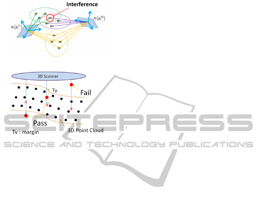
Figure 7: Interference in Hough voting.
Figure 8: Verification process.
in order to represent the 3D pose, the number of
green reference points must be three or more, i.e.,
K
g
≧ 3. Hough voting is performed independently in
each green Hough space, which is reduced to three di-
mensions (see Figure 6). Hough voting is performed
for the m-th reference point ensemble as follows:
V
k
(o
(m)
k
) = V
k
(o
(m)
k
) + 1 (16)
(k = 1, 2, · ·· , K
g
)
where V
k
(o
(m)
k
) denotes the counter value at position
o
(m)
k
in the k-th green Hough space.
Although a six-dimensional voting space is gener-
ally needed for 3D recognition, the six-dimensional
voting space has been decomposed into K
g
three-
dimensional spaces in the proposed method. In other
words, the space complexity is reduced from O(J
6
) to
O(K
g
J
3
), where J denotes the dimension of one side
of the Hough space. However, interference occurs
as a reaction to the dimensionality reduction. Even
though two poses are different, some (although not
all) green reference points would be the same position
in 3D Hough space (see Figure 7). This phenomenon
is referred to as interference, which causes a degra-
dation in recognition accuracy. A simple method by
which to suppress the decrease in recognition accu-
racy due to interference is to increase the number of
reference points in the reference point ensemble.
Verification is performed using red reference
points before Hough voting. In other words, only the
reference point ensemble passing through the verifi-
cation is used for Hough voting. Since every red refer-
ence point in the reference point ensemble is set on the
model surface or inside the model, the generated hy-
pothesis should fail when observed outside the object.
The proposed verification process is shown in Figure
8. When a red reference point is observed closer to
the scanner than the 3D point cloud, the hypothetical
pose is set as Fail. Otherwise, the hypothetical pose
is set as Pass.
The decomposition of the voting space as well as
the verification of the generated hypothetical pose by
green or red reference points has been shown exper-
imentally to be effective for 3D recognition (as de-
scribed in the next section). In other words, in an
experiment involving industrial component recogni-
tion, the computational costs as well as the robustness
with respect to occlusion and clutter are improved by
a well-designed reference point ensemble.
3.4 Ranking of Generated Hypotheses
A generated reference point ensemble is a hypotheti-
cal 3D pose of a given object. Based on the generated
hypothetical pose, Hough voting is performed using
Equation (16). The number of votes by the generated
reference point ensemble thus far is estimated to be as
follows:
V
min
= min
k
{V
k
(o
k
)} (17)
where o
k
(k = 1, 2, ··· , K
g
) is the position of the k-
th green reference point. In Equation (17), the min
operation is the best way to suppress the influence
of interference caused by dimensionality reduction.
The proposed ranking method of generated hypothe-
ses is shown in Figure 9. When V
min
is just beyond the
threshold T
c
, the generated reference point ensemble
is registered in the promising hypothesis list (PHL).
After all votes have been cast, the hypotheses in PHL
are ranked according to the final vote results. In other
word, each hypothesis in the PHL is re-evaluated us-
ing Equation (17), and is ranked according to its re-
evaluated value combined with non-maximum sup-
pression technique. The top of the ranking is used as
3D recognition result. The PHL not only suppresses
the influence of interference but also improves the
processing speed. The proposed ranking method is
shown to work very efficiently in the next section.
4 EXPERIMENTS
We applied the proposed method to two different
types of industrial components, namely, (a) a tube-
shaped Y branch (tube) and (b) a plate-shaped bracket
3DObjectRecognitionbasedontheReferencePointEnsemble
265
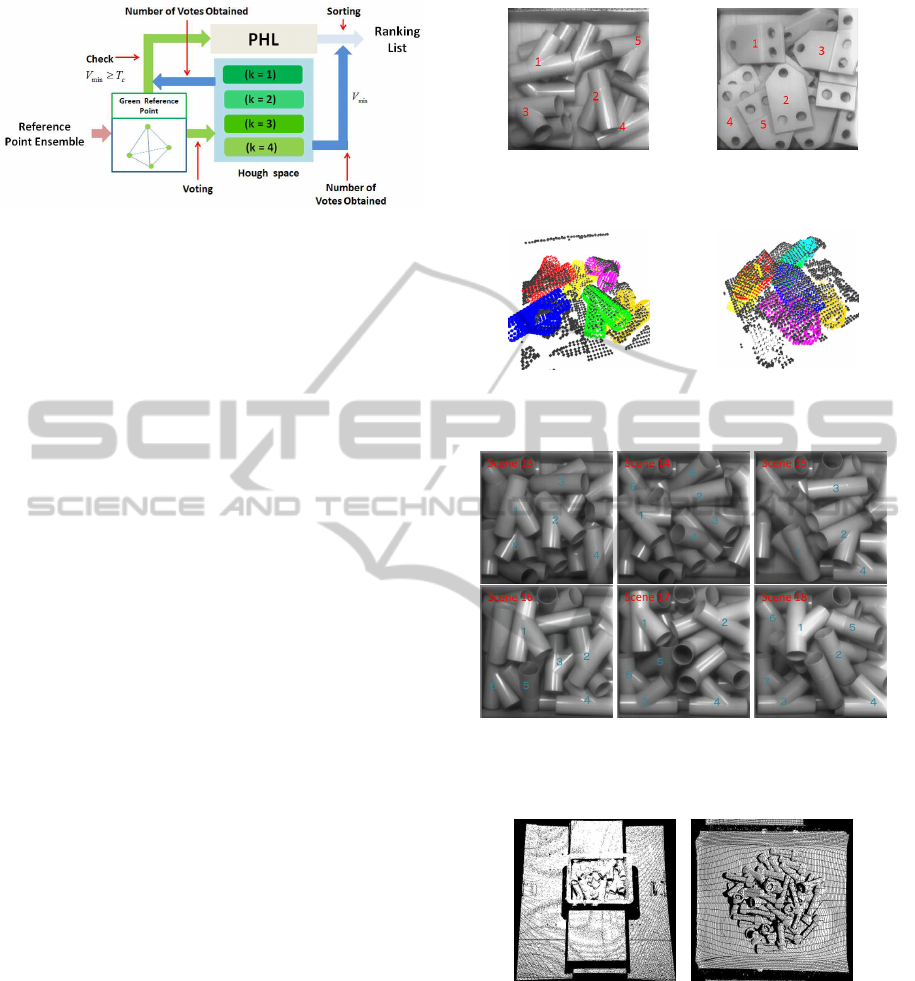
Figure 9: Fast ranking using the promising hypothesis list
(PHL).
(plate) (see Figures 4 and 10), and evaluated its per-
formance. While the tube in Figure 4(a) consists of
curved surfaces, the plate in Figure 4(b) consists of
planar surfaces.
In the first experiment, a single tube is used as an
object for 3D recognition (see Figure 4(a)). The pro-
posed method has been applied to 41 scenes, each of
which includes a single tube in a unique pose. For
the case of using three green reference points (K=3,
K
g
=3, K
r
=0) with an F-type L-Surflet-Pair, the ac-
curacy of 3D recognition is 75.6%, i.e., among the
41 scenes, the pose is not correctly recognized 10
times. On the other hand, the accuracy is 100% for
the case of using four green reference points (K=4,
K
g
=4, K
r
=0) with an F-type L-Surflet-Pair. This ex-
periment shows that a small increase in the number
of green reference points significantly improves the
accuracy of 3D recognition. In other words, a small
increase in redundancy suppresses the influence of in-
terference resulting from a dimensionality reduction.
The maximum length of the tube used in the experi-
ment is 120 [mm]. Pose errors of less than 5 [mm] and
5 [deg] are acceptable. Otherwise, the 3D recognition
is regarded as having failed.
In the second experiment, a pile of tubes is used
as objects for 3D recognition (see Figure 10(a)). The
last six of the eighteen scenes are shown in Figure 12.
Each scene includes approximately six tubes. Among
them, tubes indicated by numbers are for experiment
of 3D recognition. The total number of tubes to be
recognized is 110. The number of green reference
points used in this experiment is four (K=4, K
g
=4,
K
r
=0) and an F-type L-Surflet-Pair is used. The ex-
perimental results are shown in Table 2. For tube
recognition, the proposed method has high recogni-
tion performance without the need for verification.
In the third experiment, the proposed method with
ICP (Besl and Mckay, 1992) has been applied so as
to pick up each tube shown in Figure 13(a), which
shows 18 tubes in a box. In this experiment, the num-
ber of green and red reference points are four and
two, respectively (K=6, K
g
=4, K
r
=2), and an F-type
(a) Tubes (b) Plates
Figure 10: Examples of input scenes.
(a) Tubes (b) Plates
Figure 11: Examples of 3D recognition.
Figure 12: The last six of the eighteen scenes of a pile of
tubes. In each scene, tubes indicated by numbers are for
experimet of 3D recognition.
(a) Tubes (b) Bolts
Figure 13: Two piles of parts for bin picking.
L-Surflet-Pair is used. The experimental results are
shown in Table 3. We successfully picked up every
tube in just 18 trials (see Figure 14). In this exper-
iment, two red reference points (K
r
=2) were used in
order to ensure the precision of 3D recognition.
In addition to the tubes, the proposed method was
applied to picking up bolts, as shown in Figure 13(b).
Fifty bolts of four different sizes each were used in
VISAPP2014-InternationalConferenceonComputerVisionTheoryandApplications
266
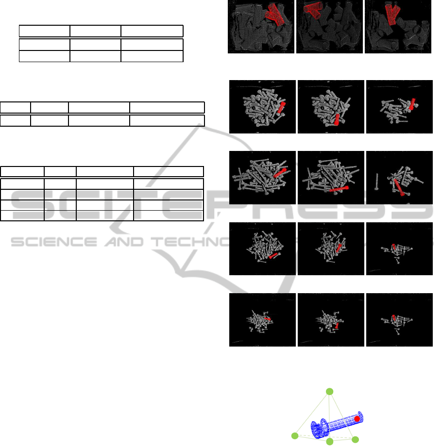
Table 2: Experimental results for tubes. (The total number
of parts to be recognized is 110, as shown in Figure 10.)
Threshold Recall[%] Precision[%]
T1 87.3 100
T2 100 76.9
Table 3: 3D recognition results for tube picking. (The pro-
cessing time includes the ICP processing time.)
Part #Trials Success Rate Processing Time
Tube 18 100 [%] 0.32 [s]
Table 4: 3D recognition results for bolt picking. (The pro-
cessing time includes the ICP processing time.)
Bolt Size #Trial Success Rate Processing Time
M12x40 50 100 [%] 0.28 [s]
M10x70 50 100 [%] 0.24 [s]
M8x30 51 98.0 [%] 0.26 [s]
M6x20 55 90.9 [%] 0.40 [s]
this bin picking experiment (see Figure 15). The con-
figuration of the reference points is shown in Figure
16, where K=5, K
g
=4, and K
r
=1. The experimen-
tal results for the bolts are shown in Table 4. Al-
though a few trials have failed for small bolts, we
have succeeded in picking up every bolt of every size
as shown in Figure 15. These results indicate that
a well-designed reference point ensemble ensures a
sufficient success rate for bin picking. In the bin pick-
ing experiment, pose errors, which are not perceived
almost visually, are acceptable. Otherwise, the 3D
recognition is regarded as having failed and an addi-
tional trial is performed. The experiment is performed
using Visual Studio C++ 2010 Express OpenMP on a
Xeon 3.5-GHz (quad-core) processor with 8 GB of
memory running on Windows 7 (64 bit).
Finally, we applied the proposed method to the
plate shown in Figure 17 and evaluated the perfor-
mance of the proposed method in the same manner as
for the tube. Figure 17 shows the last six of the eigh-
teen scenes, each of which includes approximatelysix
plates. Among them, plates indicated by numbers are
for experiment of 3D recognition (103 plates in to-
tal). Three green reference points and two or zero red
reference points are used in the final experiment, i.e.,
K=3 (K
g
=3, K
r
=0) or K=5 (K
g
=3, K
r
=2). Two types
of L-Surflet-Pairs (F-type or E-type) are used, and the
performances of the F-type or E-type pairs are com-
pared.
The experimental results are shown in Figure 18.
Both recall and precision when using an E-type L-
Surflet-Pair are greatly improved compared to the use
of an F-Type L-Surflet-Pair because the mutual infor-
mation of the E-type L-Surflet-Pair is much greater
Figure 14: Images of tubes used in the bin picking process.
(a) M12x40 bolts
(b) M10x70 bolts
(c) M8x30 bolts
(d) M6x20 bolts
Figure 15: Images of bolts used in the bin picking process.
Figure 16: The reference point ensemble designed for bolt
(K=5, K
g
=4, K
r
=1).
than that of an F-type L-Surflet-Pair with respect to
the plate. The total number of C-matrices listed in the
R-table for the F-type L-Surflet-Pair is much greater
than that for the E-type L-Surflet-Pair. This means
that the F-type surflet pair is not suitable for pla-
nar shaped parts but works very well for cylindrical
parts. The performance is also confirmed o be im-
proved through verification using red reference points
(see Figure 15: E-V is better than E-N). This is be-
cause wrong votes are suppressed by the verification
process. For bin picking of the plate, an E-type L-
3DObjectRecognitionbasedontheReferencePointEnsemble
267
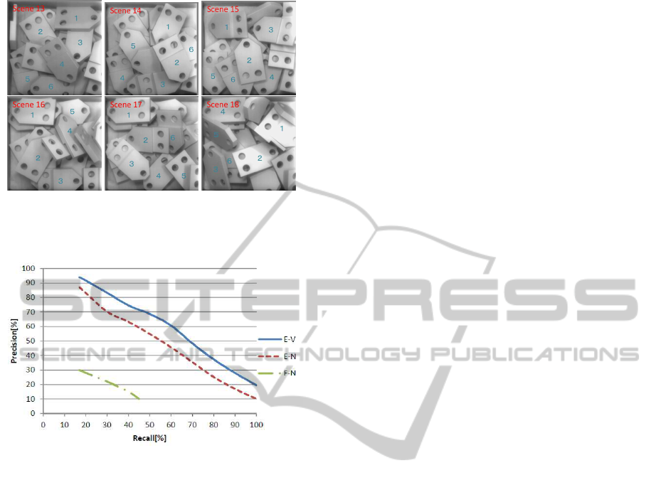
Figure 17: The last six of the eighteen scenes of a pile of
plates. In each scene, plates indicated by numbers are for
experiment of 3D recognition.
Figure 18: Experimental results for the plate. F-N shows
the results obtained using the F-type L-Surflet-Pair without
verification (K=3, K
g
=3, K
r
=0). E-N shows the results ob-
tained using the E-type L-Surflet-Pair without verification
(K=3, K
g
=3, K
r
=0). E-V shows the results obtained us-
ing the E-type L-Surflet-Pair with verification (K=5, K
g
=3,
K
r
=2).
Surflet-Pair with a reference point ensemble consist-
ing of four green reference points and more than two
red reference points (K=6, K
g
=4, K
r
≧ 2) is recom-
mended. For bin picking a mixture of the plate and
the tube, the proposed method can be applied@same
as in the homogeneous case.
5 CONCLUSIONS
In the present paper, we have proposed a high-
performance 3D recognition method based on the ref-
erence point ensemble, which is a natural extension
of the generalized Hough transform. The reference
point ensemble consists of several color-coded refer-
ence points. Red reference points are used for veri-
fication of the hypothesis, and green reference points
are used for voting of the hypothesis in the 3D Hough
space. The proposed method has the following two
different modes:
(A) Individual mode: Voting of the hypothesis inde-
pendently in each green Hough space and veri-
fying of hypothesis with red reference points are
done in this mode.
(B) Ensemble mode: Verifying of registration into
PHL and aggregating of total votes are done in
this mode.
The efficient recognition has been achieved by skill-
fully switching the above two modes. This mecha-
nism is the most significant characteristic of the pro-
posed method. In the proposed method, a set of ref-
erence point ensembles is generated by a local fea-
ture referred to as the L-Surflet-Pair. Each generated
reference point ensemble is a hypothetical 3D pose
of given object in the scene. Effective recognition
of the reference point ensemble has led to robust 3D
recognition of a pile of industrial parts. An exper-
iment involving industrial parts recognition has re-
vealed that both robustness with respect to noise and
computational cost are improved by a well-designed
reference point ensemble. Interference suppression
and hypothesisverification, which are designed by the
reference point ensemble, are also demonstrated to
improve 3D object recognition performance. More-
over, the L-Surflet-Pair is newly proposed as an ex-
tension of the Surflet-Pair. This extension was espe-
cially successful for planar-shaped part recognition,
although challenges remain. For the case in which
the image area of a given part is relatively small,
the reference point ensemble is difficult to generate
stably based on the L-Surflet-Pair. Furthermore, the
proposed method has difficulty in recognizing certain
shapes, such as needle-shaped objects, string-shaped
objects, and combinations thereof. This remains a
challenge for future research.
REFERENCES
Ballard, D. H. (1981). Generalizing the hough transform to
detect arbitrary shapes. In Pattern Recognition, 13(2)
pages 111-122.
Besl, P. J. and Mckay, N. D. (1992). A method for registra-
tion of 3-d shapes. In IEEE Trans. on Pattern Analy-
sis and Machine Intelligence(Los Alamitos, CA, USA:
IEEE Computer Society) 14 (2) : 239-256.
Chua, C. S. and Jarvis, R. (1997). Point signatures: A new
representation for 3d object recognition. In Interna-
tional Journal of Computer Vision, 25(1):63-85.
Drost, B., Ulrich, M., Navab, N., and Ilic, S. (2010). model
globally, match locally: efficient and robust 3d object
recognition. In Proc. IEEE Computer Vision and Pat-
tern Recognition(CVPR), pp.998-1005.
VISAPP2014-InternationalConferenceonComputerVisionTheoryandApplications
268

Johnson, A. E. and Hebert, M. (1999). Using spin images
for efficient object recognition in cluttered 3d scenes.
In Trans. IEEE Pattern Analysis and Machine Intelli-
gence(PAMI), vol. 21, no. 5, pp.433-449.
Kim, E. and Medioni, G. (2011). 3d object recognition in
range images using visibility context. In IEEE/RSJ In-
ternational Coference on Intelligent Robots and Sys-
tems(IROS), pages 3800-3807.
Mian, A., Bennamoun, M., and Owens, R. (2010). On the
repeatability and quality of keypoints for local feature-
based 3d object retrieval from cluttered scenes. In In-
ternational Journal of Computer Vision, Volume 89 Is-
sue 2-3.
Mian, A. S., Bennamoun, M., and Owens, R. (2006). Three-
dimensional model-based object recognition and seg-
mentation in cluttered scenes. In IEEE transac-
tions on pattern analysis and machine intelligence,
28(10):1584-1601.
Rabbani, T. and Heuvel, F. V. D. (2005). Efficient hough
transform for automatic detection of cylinders in point
clouds. In In Proceedings of the 11th Annual Con-
ference of the Advanced School for Computing and
Imaging(ASCI05), volume 3, pages 60-65.
Rusu, R. B. (2010). Sematic 3d object maps for everyday
manipulation in human living environments. In Arti-
cial Intelligence(KI-Kuenstliche Intelligenz).
Rusu, R. B., Blodow, N., and Beetz, M. (2009). Fast point
feature histograms(fpfh) for 3d registration. In In
Proceedings of the IEEE International Conference on
Robotics and Automation(ICRA), Kobe, Japan,pages
3212-3217.
Sun, Y., Paik, J., Koschan, A., Page, D. L., and Abidi, M. A.
(2003). Point fingerprint: a new 3-d object representa-
tion scheme. In IEEE Transactions on Systems, Man,
and Cybernetics, Part B, 33(4):712-717.
Tombari, F., Salti, S., and Stefano, L. D. (2010). Unique
signatures of histograms for local surface descrip-
tion. In 11th European Conference on Computer Vi-
sion(ECCV), September 5-11, Hersonissos, Greece.
Tombari, F. and Stefano, L. D. (2010). Object recognition in
3d scenes with occlusions and clutter by hough voting.
In 2010 Fouth Pacific-Rim Symposium on Image and
video Technology, pages 349-355.
Wahl, E., Hillenbrand, U., and Hirzinger, G. (2003). Surflet-
pair-relation histograms: A statistical 3d-shape rep-
resentation for rapid classification. In Forth Interna-
tional Conference on 3-D Digital Imaging and Mod-
eling(3DIM 2003) 6-10 October 2003, Banff, Alberta,
Canada, IEEE Computer Society Press, pages 474-
481.
3DObjectRecognitionbasedontheReferencePointEnsemble
269
