
Grasping Guidance for Visually Impaired Persons based on Computed
Visual-auditory Feedback
Michael Hild and Fei Cheng
Graduate School of Engineering, Osaka Electro-Communication University,
Hatsu-cho 18-8, Neyagawa 572-8530, Osaka, Japan
Keywords:
Visual Feedback, Grasping, Human as Actuator, Commands-by-Voice.
Abstract:
We propose a system for guiding a visually impaired person toward a target product on a store shelf using
visual–auditory feedback. The system uses a hand–held, monopod–mounted CCD camera as its sensor and
recognizes a target product in the images using sparse feature vector matching. Processing is divided into two
phases: In Phase1, the system acquires an image, recognizes the target product, and computes the product
location on the image. Based on the location data, it issues a voice–based command to the user in response to
which the user moves the camera closer toward the target product and adjusts the direction of the camera in
order to keep the target product in the camera’s field of view. When the user’s hand has reached grasping range,
the system enters Phase 2 in which it guides the user’s hand to the target product. The system is able to keep
the camera’s direction steady during grasping even though the user has a tendency of unintentionally rotating
the camera because of the twisting of his upper body while reaching out for the product. Camera direction
correction is made possible due to utilization of a digital compass attached to the camera. The system is also
able to guide the user’s hand right in front of the product even though the exact product position cannot be
determined directly at the last stage because the product disappears behind the user’s hand. Experiments with
our prototype system show that system performance is highly reliable in Phase 1 and reasonably reliable in
Phase 2.
1 INTRODUCTION
Visually impaired persons are faced with many dif-
ficult tasks in their everyday lives. One of them is
the task of shopping in a store. At first, the person
must navigate to the store, then navigate within the
store to the shelf with the target product, and finally
she/he must approach the target product and grasp it
with her hand. For visually unimpaired persons, all of
these tasks involve the person’s visual capability, but
a visually impaired person has to rely on other means
to carry out these tasks. In this paper we propose a
system for supporting a visually impaired person to
carry out the product grasping step of the shopping
task. The system uses a camera for sensing the scene
and recognizing the product which the user wishes to
buy, and based on the recognition results it guides the
user toward the product by issuing voice commands to
the user according to which she/he moves the camera.
In this way, the system provides feedback about the
product’s relative location based on visual analysis,
but the commands derived from the analysis results
are conveyed to the user in auditory form. Solutions to
the grasping problem based on visual feedback have
been investigated in the past, but those efforts focused
on the implementation of the grasping capability for
robots, where the actuator element in the visual feed-
back loop is some kind of electro–mechanical device
which moves the robot’s hand toward the object to be
grasped. (Chinellato and del Pobil, 2005) In the pro-
posed system, the actuator in the feedback loop is a
human being who in many ways is more difficult to
control than an electro–mechanical device.
There is a large body of literature on visual feed-
back applications most of which are related to the
field of robotics and control. There are also many
publications discussing supporting technologies for
visually impaired persons based on vision techniques;
the bulk of it focuses on navigation in various envi-
ronments, obstacle detection, and detection of spe-
cific objects. The paper in (T. Winlock and Belongie,
2010) proposes a method for detecting grocery on
shelves for assisting visually impaired persons, but
the aspect of assisting the person to grasp the desired
item is not treated.
In the next section we provide the outline of the
75
Hild M. and Cheng F..
Grasping Guidance for Visually Impaired Persons based on Computed Visual-auditory Feedback.
DOI: 10.5220/0004653200750082
In Proceedings of the 9th International Conference on Computer Vision Theory and Applications (VISAPP-2014), pages 75-82
ISBN: 978-989-758-009-3
Copyright
c
2014 SCITEPRESS (Science and Technology Publications, Lda.)

system. Then we discuss the image processing and
matching methods used, followed by a description of
the feedback control algorithm for guiding the user
toward the object so that she/he can grasp it. Next,
experimental results are presented and a summary is
given.
2 OUTLINE OF THE SYSTEM
The grasping support system proposed in this paper
is based on visual feedback, but unlike most visual
feedback systems proposed to date, the actuator in the
system is a person whose vision is impaired. That is,
the grasping of the desired object is carried out by the
person’s hand, and the camera providing information
about the environment is also moved by the person’s
hand. At the start of the grasping action, the human
actuator holding the camera in one hand is placed at
a certain distance from the target object, and the cam-
era captures the target scene. The system recognizes
the target object in the obtained image and makes a
judgement about its location on the image. Based
on this location, a command is generated for the pur-
pose of providing auditory (voice) instructions to the
human actuator about how to make the next camera
move in a way that the camera will approach the tar-
get object without loosing track of the target object
in the field of view. The human actuator then moves
the camera according to the command, which results
in further approaching the target object by some finite
distance. Then the camera captures a new image, and
the same cycle is repeated until the camera and human
actuator will be close enough for the human actuator
to be able to grasp the object with her/his hand. A
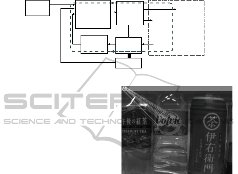
schematic view of this visual-auditory feedback loop
is shown in Fig. 1, where the visual feedback loop is
indicated by the sequence {light field → camera →
image analysis → audio–based command generation
→ human actuator → camera motion → } (along the
dashed line). The connection between human actua-
tor and camera is meant to indicate that the camera is
manipulated by the person’s hand. This feedback loop
includes the scene in front of the camera (i. e. the
shelf with products) because the camera motion oc-
curs within the scene and the camera senses the light
field originating in the scene.
There is a second loop which is comprised of the
sequence {camera → compass → audio–based com-
mand generation → human actuator → } in which a
compass sensor for measuring the camera’s heading
is included. This heading sensor is mechanically at-
tached to the camera; it is used to assist in keeping
the camera’s direction stable. The second loop is also
a feedback loop including the human actuator, but it
is not based on vision. It works in parallel to the first
loop and involves only auditory feedback.
Since the camera is moved by a person who is
unable to observe the camera due to his/her visual
impairment, there inevitably will be some amount of
camera position jitter. This jitter leads to image blur if
the camera’s exposure time is set to about 1/60 second
(which is not unusual under dim scene illumination
sometimes found in stores). In order to stabilize the
camera, we mount the camera on a monopod, which
stabilizes the camera in vertical direction. The mono-
pod allows the person to adjust the camera’s height.
The reason for choosing a monopod over a tripod is
that the tripod would be too bulky to handle, whereas
a monopod is slim and yet providing sufficient, al-
though not absolute stability.
The visual-auditory feedback process described
above involves two different phases: 1. the gradual
approach toward the target object from some distance,
and 2. the actual grasping of the object by the per-
son’s hand. In the following, we explain the details
of Phase 1 and Phase 2, as well as the details of the
image processing and object recognition methods that
are common to both phases.
3 IMAGE PROCESSING AND
MATCHING
In a system as outlined above, recognition of target
objects in the images and estimating their position in
the image coordinate system is crucial to the success
of the system. Of similar importance is the identifica-
tion of the user’s hand and the estimation of the hand
position during the final stage of the grasping process.
3.1 Recognition of Target Object and
Position Estimation
For the recognition of objects, stable and descriptive
features of the object have to be extracted from the
image. We use the SIFT feature vectors (Lowe, 2004)
for this purpose because these features are relatively
stable to scale and orientation changes of the pro-
jected object images. As the user moves the cam-
era closer to the target object, the object size on the
images increases, and there are also camera direction
changes within a certain angular range because the
camera is mounted on a monopod held by the user’s
hand, which cannot keep the camera completely sta-
ble. SIFT feature vectors are designed to cope with
this situation, although the time needed for computing
VISAPP2014-InternationalConferenceonComputerVisionTheoryandApplications
76
human
)
*
audio-based
command
generation
human
actuator
camera
motion
grasping
action
light
field
)
*
camera
compass
image
analysis
product
info,
start/stop
scene
*
) same
person
Figure 1: Visual-auditory feedback loop with human actuator.
them is said to be relatively long. As the computation
time of SIFT feature vectors is not critical in the con-
text of our system, we settled for SIFT, although there
are other possible choices, for example the SURF fea-
ture vectors. (H. Bay and Gool, 2008)
First, the objects to be recognized have to be rep-
resented in terms of SIFT feature vectors. For this
purpose we take the image of the objects from a rel-
atively far distance (for example 1.5 m) and extract
SIFT vectors within a rectangular window placed on
the characteristic part of the object. The set of ex-
tracted vectors v
T
j
, j = 1, 2, ...., J is called template
in this paper and is used as the object representation.
Note that the position information of the vectors is not
saved, which is different from the usual usage of the
term template. SIFT vectors are extracted from the
intensity image.
During Phase 1 and Phase 2, at each processing
step scene images are acquired by the camera and
SIFT vectors v
I
k
, k = 1, 2, ...., K are extracted from
the entire image for the purpose of using them for the
recognition of the target object in the image. Con-
cretely, the SIFT vectors included in the target ob-
ject’s template, v
T
j
, are matched to all vectors v
I
k
in
an exhaustive search which is expressed by Eqn.(1).
{v
T
j
, v
I
k
}
min
= min
k
D(v
T
j
, v
I
k
), ∀ j, k (1)
The vector that is considered to be the best match to
vector v
T
j
is found by selecting that vector v
I
k
from all
vectors extracted from the image for which the dis-
tance D(·, ·) is minimal. In addition to this, we re-
quire that the matched distance must be smaller than
a preset threshold D
0
, i. e. we require D(v
T
j
, v
I
k
) < D
0
for a match to be valid. Carrying out this matching
process for each vector in the template generates a set
of matched vector pairs ⟨v
T
j
, v
I
k
⟩, where j = 1, 2, ..., J
with some of the j–numbers possibly missing, and for
a given j there is only one number k from the range
k = 1, 2, ..., K.
Figure 2: Line segments between matched template vectors
and image vectors.
The set of matched vector pairs ⟨v
T
j
, v
I
k
⟩ may in-
clude some pairs that are not correct. Such vector
pairs are labeled as mismatch. In order to find and
eliminate such vectors, we require that the spatial
relationships between matched vector pairs must be
consistent. Concretely, we execute the following pro-
cedure:
First, we combine the scene image and the template
image such that the template image is located above
the right–upper corner of the scene image as is shown
in the example of Fig.2. In this combined image,
the positions of matched vector pairs ⟨v
T
j
, v
I
k
⟩ can be
thought of as being connected by straight line seg-
ments, where each line segment is described by a
pair of parameters (α, l), which represent the angle
between the line segment and the x–axis of the im-
age coordinate system, and the line segment’s length,
respectively. If we assume that the orientation of
the template image and the orientation of the object
in the scene image are not radically different and
each matched feature vector pair has been correctly
GraspingGuidanceforVisuallyImpairedPersonsbasedonComputedVisual-auditoryFeedback
77

matched, the histogram H(α) of the angles α
jk
of all
matched feature vector pairs, as well as the histogram
H(l) of the line segment lengths l
jk
of all matched
feature vector pairs will be unimodal and the two his-
tograms will not include statistical outliers. On the
other hand, the parameters (α, l) of vector pairs which
are mismatches will show up in these histograms as
outliers. Consequently, mismatched vector pairs can
be identified by identifying those outliers. For out-
lier identification we use the Least Median of Squares
(LMS) method (Rousseeuw and Leroy, 1987) and
compute the robust mean location α
0
of angles α and
the robust mean location l
0
of lengths l, as well as the
robust standard deviations σ
α
and σ
l
, and determine
the outlier values for the α and l value distributions.
Those matched vector pairs
⟨
v
T
j
, v
I
k
⟩ that correspond
to identified outliers of either α or l are then elim-
inated from the set of matched feature vector pairs.
Values are identified as outliers if they do not satisfy
the following conditions:
(α
0
− 2.5 · σ
α
) < α < (α
0
+ 2.5 · σ
α
) (2)
(l
0
− 2.5 · σ
l
) < l < (l
0
+ 2.5 · σ
l
)
Let the number of matched feature vector pairs
after outlier elimination be M. We consider a target
product represented by its template as recognized in
the scene image, if condition (M > N
0
) is satisfied.
N
0
denotes the minimal, absolutely necessary number
of matched feature vector pairs for acknowledging the
target object’s recognition.
Once the target object has been recognized, the
product’s position on the image is computed as the
mean of all positions of those feature vectors on the
image that have been matched correctly.
3.2 Hand Position and Distance
We extract hand region pixels based on skin color
chromaticity and use histograms H(x) and H(y) of the
locations of such pixels to determine the hand region.
The hand position (x
H
, y
H
) is determined close to the
finger tips of the right hand.
The distance D between camera and target product
is estimated from the size u of the region spanned by
the matched feature vectors on the image, and the size
u
T
of the same region of the template feature vectors
at distance D
T
= 1.5 m as
D =
u
T
u
· D
T
(3)
4 FEEDBACK CONTROL
ALGORITHM IMPLEMENTING
GUIDANCE FOR GRASPING
At the start of the product grasping process, the vi-
sually impaired user stands in front of the product
shelf and subsequently has to be guided toward the
target product through system–generated voice com-
mands. In Phase 1 of this process, she is guided so
that she can approach the target object step–by–step.
In this phase, the user moves her body together with
the monopod–mounted camera, where both hands of
the user rest on the upper part of the monopod. We
envision that Phase 1 takes place in a distance range
between 1.5 m and the interval [0.4, 0.28] m, which is
close enough for the user to extent her hand to the tar-
get product. In Phase 2, the user’s body is stationary,
and her left hand holds the monopod, while her right
hand is guided to the target product through system–
generated voice commands. The user may also have
to rotate the camera by her left hand in both phases.
A detailed description of the control algorithm used
to accomplish this is provided in the next two subsec-
tions.
4.1 Phase 1: Guiding the User toward
the Target Product
At the start of Phase 1, the user has already selected
the target product and is standing in front of the prod-
uct shelf. She holds the camera mounted on the mono-
pod in her hands and awaits voice commands from
the system. The camera is roughly pointed toward
the shelf. This is the situation when the algorithm for
guiding the user toward the target product is started.
But before stating the algorithm, we introduce some
essential issues necessary for its explanation.
During the approach toward the target product,
the camera direction must be kept pointed toward the
product. This means that the projected image of the
product must appear in the center of the image. In or-
der to test whether the product is projected to the im-
age center, we divide the image plane into five sectors
as is shown in Fig.3. If the mean position of the prod-
uct’s matched feature vectors is located in the rectan-
gle in the image center, the product is judged to be in
the center of the image. If it is in sector 1, the cam-
era needs to be rotated to the right and ⟨Command:
Turn the camera to the right⟩ is issued; if it is in sec-
tor 3, ⟨Command: Turn the camera to the left⟩ is is-
sued; if it is in sector 2, ⟨Command: Turn the camera
upward⟩ is issued; and if it is in sector 4, ⟨Command:
Turn the camera downward⟩ is issued. One of these
VISAPP2014-InternationalConferenceonComputerVisionTheoryandApplications
78

commands is substituted for ⟨Command: Move the
camera to X⟩ in step (5) of the algorithm stated be-
low.
width
x
y
height
2
13
4
central
rectangle
1: move the camera right
2: move the camera up
3: move the camera left
4: move the camera down
Figure 3: Sectors for determining the direction of camera
rotation.
Since rotation of the camera is executed by the left
hand of the visually impaired user, there is always the
possibility that the camera is rotated too far, in which
case the product would no longer be projected onto
the image plane. This happens particularly often with
left/right rotations, and when the camera is close to
the product. In order to prepare for the recovery from
such a situation, we acquire the first scene image dur-
ing the initialization step at the start of Phase1, extract
feature vectors and determine the position of the prod-
uct on the image. Then we set two windows, one to
the left of the product, W
l
, and one to the right of the
product, W
r
. The size of these windows is the same
as the size of the product label. Next we extract fea-
ture vectors in each of these windows and save them
for later use. These feature vectors are used in step
(8) in the algorithm described below. As these feature
vectors represent information about areas to the left
and right of the product label, they will be useful for
recovery from situations in which the camera rotation
had gone too far.
The Control Algorithm for Phase 1 can be
stated as follows:
1. Initialization: Prepare the template vector set cor-
responding to the target product selected by the
user. Then acquire the first image of the scene and
carry out matching between template and image
feature vectors. If the target product can be recog-
nized, extract SIFT feature vectors in the windows
W
l
and W
r
and save them.
2. Acquire a scene image and carry out matching.
3. If the target product could not be recognized, go
to step (8), else proceed to step (4).
4. Compute the product’s position on the image.
5. If the position is not in the image center, issue
⟨Command: Move the camera to X⟩, wait 5 sec-
onds and return to step (2). Else proceed to step
(6).
6. Compute distance D between camera and target
product.
7. Based on distance D, select one of the four cases:
• If (0.28 ≤ D ≤ 0.4)m holds, terminate Phase 1
and start Phase 2.
• If (D > 0.5)m, issue ⟨Command: Move
forward⟩, wait 5 seconds and return to step (2).
• If (0.4 < D ≤ 0.5)m, issue ⟨Command: Move
slightly forward⟩, wait 5 seconds and return to
step (2). I. e., the camera must not be moved too
close to the target object, which would result in
a blurred image.
• If (D < 0.28)m, issue ⟨Command: Move
backward⟩, wait 5 seconds and return to step
(2).
8. Recovery attempt from lost-object-situation:
First, match feature vectors from window W
l
(see
step (1)) and the vectors from the entire scene
image, and count the number of matched vector
pairs, n
L
. If (n
L
> N
0
) (with N
0
being some thresh-
old) holds, consider the product to be recognized
and issue ⟨Command: Turn camera to the right⟩,
wait 5 seconds and return to step (2). Else con-
tinue to step (9).
9. Match the feature vectors from window W
l
and
the vectors from the entire scene image, and count
the number of matched vector pairs, n
R
. If (n
R
>
N
0
) holds, consider the product to be recognized
and issue ⟨Command: Turn camera to the left⟩,
wait 5 seconds and return to step (2). Else proceed
to step (10).
10. Issue ⟨Statement: Recognition failed⟩.
For some reason, the product could not be rec-
ognized in spite of the recovery attempt, which
means that Phase 1 should be discontinued now,
and re–started.
4.2 Phase 2: Guiding the User’s Hand
to the Target Product
In Phase 2, the system guides the user’s right hand to
the target product to enable her to grasp the product.
The control algorithm for this phase has to account for
two peculiarities of the grasping process which will be
described before we state the algorithm.
Camera Direction Shift due to Body Twisting
The distance between the user’s hand and the prod-
uct at the end of Phase 1 will be in the range (0.28 ≤
D ≤ 0.4) m. If the user’s right hand is located at the
far end of this range, the user will have to stretch out
her arm, which often is accompanied by a twisting of
GraspingGuidanceforVisuallyImpairedPersonsbasedonComputedVisual-auditoryFeedback
79

her body. This is due to the fact that the upper part
of human body unintentionally turns slightly to the
left when the user stretches out her right arm. At the
same time, the user strives to keep the spatial rela-
tionship between the camera and her body rigid, and
therefore the camera, too, will make a slight turn to
the left. This will cause the product’s image to shift
on the image plane, and sometimes so much that the
product will completely shift out of the camera’s field
of view. This is all the more the case as the camera is
now very close to the product. As a countermeasure
to this problem, we attach a digital compass sensor to
the camera in order to directly measure the camera di-
rection before and after the user’s reaching out to the
product. If the direction shift is too large, the system
issues commands to the user so that she can rotate the
camera back to its former direction.
Impossibility of Product Position Estimation
In Phase 2, the user’s hand must be guided by the sys-
tem such that the hand position and the product posi-
tion become close on the image plane. As the hand
will be in front of the product at this final stage, ob-
serving and determining the product position directly
is impossible. As an indirect method for estimating
the product position on the image plane, we introduce
window W
p
having corner points [(0, 0); (x
H
, h)],
where (x
H
, y
H
) is the hand position and h is the height
of the image. I. e., the window always covers part of
the left side of the image up to the hand position. If
we match product template feature vectors and im-
age feature vectors extracted within window W
p
and
count the successful matches as n
k
, we can distinguish
three fundamental cases with respect to n
k
:
• There are almost no matches in W
p
, i.e. (n
k
<
4). Here, the hand position must be to the left of
the product area and hence the hand needs to be
moved to the right.
• There are almost as many matches in W
p
as the
number of feature vectors n contained in the prod-
uct template, i.e. (n
k
>
2
3
· n). Here, the hand po-
sition must be to the right of the product area and
hence the hand needs to be moved to the left.
• The number of matches in W
p
is about half of the
number of vectors contained in the template, i.e.
(4 ≤ n
k
≤
2
3
· n). Here, the hand position is some-
where on the product area and hence the hand is
in a position from where it can grasp the product.
The Control Algorithm for Phase 2 can be
stated as follows:
1. Measure the camera’s heading using the compass
sensor and save this value as base heading α
0
.
2. Issue ⟨Command: Move your right hand between
camera and product⟩ to the user. Wait for 5 sec-
onds and issue ⟨Command: Move your right
hand toward the product⟩. The user responds by
moving her right hand until she touches a prod-
uct. The reason for using two separate commands
here is to keep the commands simple and easy to
execute.
3. Measure the camera’s heading, α
1
, again and
compute the rotation angle ∆α = α
1
− α
0
.
4. Based on angle ∆α, select one of the following
four cases:
• If (∆α < −5
◦
), issue ⟨Command: Rotate the
camera CW with your left hand⟩, wait 5 sec-
onds and return to step (3).
• If (−5
◦
≤ ∆α < −2
◦
), issue ⟨Command:
Small camera rotation CW with your left hand⟩,
wait 5 seconds and return to step (3).
• If (∆α > 5
◦
), issue ⟨Command: Rotate the
camera CCW with your left hand⟩, wait 5 sec-
onds and return to step (3).
• If (2
◦
< ∆α ≤ 5
◦
), issue ⟨Command: Small
camera rotation CCW with your left hand⟩,
wait 5 seconds and return to step (3).
• If (|∆α| ≤ 2
◦
), acquire next image, extract the
hand region, determine its area A
h
and proceed
to step (5).
5. If the hand region area A
h
is not large enough,
issue ⟨Command: Hand detection failed. Move
your right hand to the left⟩, wait 5 seconds and re-
turn to step (3). Else if the hand region area A
h
is
large enough, compute the hand position (x
h
, y
h
)
and proceed to step (6).
6. Match the feature vectors within the window and
count the number of matched vectors, n
k
.
Based on the value of n
k
, select one of the follow-
ing three cases:
• If (n
k
< 4), issue ⟨Command: Move your right
hand to the right⟩, wait 5 seconds and return to
step (3).
• If (n
k
>
2
3
n), issue ⟨Command: Move your
right hand to the left⟩, wait 5 seconds and re-
turn to step (3).
• If (4 ≤ n
k
≤
2
3
n), determine the upper and lower
boundary y
max
, y
min
of the target product and
proceed to step (7).
7. Based on the (vertical) hand position y
H
, select
one of the following three cases:
• If (y
H
< y
min
), issue ⟨Command: Move your
right hand downward⟩, wait 5 seconds and re-
turn to step (3).
VISAPP2014-InternationalConferenceonComputerVisionTheoryandApplications
80

• If (y
H
> y
max
), issue ⟨Command: Move your
right hand upward⟩, wait 5 seconds and return
to step (3).
• If (y
min
≤ y
H
≤ y
max
), issue ⟨Command: Grasp
the product⟩, and terminate the process.
5 EXPERIMENTAL RESULTS
In order to test the system proposed in this paper, we
constructed a prototype consisting of a workstation
with an Intel CPU (3.07 GHz clock) running under
Linux (Ubuntu 10.10, 64 bits) and with 2 GB main
memory, a CCD camera Chameleon CMLN-13S2C
(Pointgrey) with a lens of 8 mm focal length, a mono-
pod by Manfrotto 334B, and a digital compass mod-
ule using a 2-axis magnetic field sensor (HM6352
by Honeywell, module order-made by EYEDEA of
Kobe, Japan). We calibrated the digital compass such
that 0
◦
output coincided approximately with magnetic
north heading in Japan (2012). The digital compass
has a resolution of 0.1
◦
, and its output proves to be a
linear function of the rotation angle when it is rotated
in the geomagnetic field. Commands from the sys-
tem to the user are generated through OS commands
issued by the control program in order to play prere-
corded voice files.
We set up a shelf on which bottles of seven kinds
of soft drinks were placed, as shown in Fig.4. The
templates of these products were generated in ad-
vance. The user involved in the experiment was not
visually impaired, but he was wearing an eye cover
which completely shut out all light to his eyes. He
was placed in front of the shelf at approximately 1.5
m distance at random positions at the start of each ex-
perimental run.
Figure 4: Scene of the experiment.
We carried out 30 experimental runs and recorded
important data at each processing step. The data about
the product templates is shown in Table 1, where No.
is the template number, N
T
is the number of vectors
extracted within the template, size is the template size
in pixels, and M is the number of vectors that could be
matched to the (first) image taken at 1.5 m distance.
Table 1: Template data.
No. N
T
size [pix.] M
1 85 88× 59 28
2 238 88× 208 49
3 222 80× 230 36
4 217 83× 232 36
5 97 93× 57 10
6 129 86× 105 12
7 104 93× 59 25
Only a fraction of the original number of vec-
tors could be matched for each template, i. e. M <
N
T
. However, as M > N
0
(with N
0
= 8, the minimal
number of matched vector pairs required for positive
recognition), all templates could be recognized in the
first image.
During Phase 1, all target products could be rec-
ognized at each step in all 30 runs. On average 11
steps were carried out during Phase 1. The graph in
Fig.5 shows how the x-coordinate of the product posi-
tions on the image plane evolved with distance D dur-
ing three different experimental runs. The start of the
process is at the right end of each trace. The advances
toward the product as well as the camera rotations can
clearly be observed.
Figure 5: Product positions x vs. distance D during three
Phase 1 runs.
The positions of the seven products on the image
plane at the end of Phase 1 are shown as dots in Fig.6.
All 30 positions are within the central rectangle on the
image, which means 100% success rate for Phase 1.
Out of 30 runs, 26 runs were successfully com-
pleted until the end of Phase 2. I. e., the execution
of Phase 2 was unsuccessful in 4 runs. In Phase 2,
the hand position and the product position on the im-
age must come close enough to make grasping possi-
GraspingGuidanceforVisuallyImpairedPersonsbasedonComputedVisual-auditoryFeedback
81
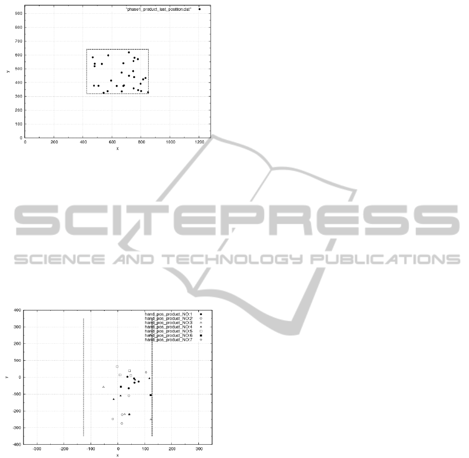
Figure 6: The positions of 30 products at the end of Phase
1.
ble. Fig.7 shows the spatial relationship of the 26 suc-
cessful hand positions and the product. The product
boundary is shown by two vertical dotted lines (which
have been normalized). The four failures were caused
by insufficient extraction of the hand region due to
similarity of skin color and product label color (in
chromaticity terms). Thus, the system by and large
was successful, but it includes a weakness in the hand
region extraction method.
Figure 7: The right–hand positions of 26 runs at the end of
Phase 2 relative to product boundaries.
6 CONCLUSIONS
In this paper we proposed a system for guiding a visu-
ally impaired person toward a target product on a store
shelf using visual–auditory feedback. The system is
able to cope with the body twisting phenomenon due
to utilization of a digital compass, and it can guide
the user’s hand to the product even though the prod-
uct position cannot be determined directly at the last
stage. Experiments with our prototype system show
that it is highly reliable in Phase 1, but needs some
improvement to the hand region extraction algorithm
of Phase 2.
REFERENCES
Chinellato, E. and del Pobil, A. P. (2005). Vision and grasp-
ing: Humans vs. robots. In IWINAC 2005, LNCS 3561
(J. Mira and J. R. Alvares (Eds.)), pages 366–375.
Springer-Verlag, Berlin Heidelberg.
H. Bay, A. Ess, T. T. and Gool, L. V. (2008). Speeded up ro-
bust features (surf). Computer Vision and Image Un-
derstanding, 110:346–359.
Lowe, D. G. (2004). Distinctive image features from scale-
invariant keypoints. International Journal of Com-
puter Vision, 60:91–110.
Rousseeuw, P. J. and Leroy, A. M. (1987). Robust regres-
sion and outlier detection, chapt. 3. John Wiley &
Sons, New York.
T. Winlock, E. C. and Belongie, S. (2010). Toward
real–time grocery detection for the visually impaired.
Computer Vision and Pattern Recognition Workshops
(CVPRW), pages 49–56.
VISAPP2014-InternationalConferenceonComputerVisionTheoryandApplications
82
