
Objects Tracking in Catadioptric Images using Spherical Snake
Anisse Khald
1
, Amina Radgui
2
and Mohammed Rziza
1
1
LRIT(URAC29-CNRST), Mohamed V-Agdal university, Rabat, Morocco
2
National Institute of Posts and Telecommunications (INPT), Rabat, Morocco
Keywords:
Spherical Snake, Omnidirectional Image, Object Tracking, Inverse Stereographic Projection.
Abstract:
The current work addresses the problem of 3D model tracking in the context of omnidirectional vision in
order to object tracking. However, there is few articles dealing this problem in catadioptric vision. This
paper is an attempt to describe a new approach of omnidirectional images (gray level) processing based on
inverse stereographic projection in the half-sphere. We used the spherical model. For object tracking, The
object tracking method used is snake, with optimization using the Greedy algorithm, by adapting its different
operators. This method algorithm will respect the deformed geometry of omnidirectional images such as the
spherical neighbourhood, the spherical gradient and reformulation of optimization algorithm on the spherical
domain. This tracking method - that we call spherical snake - permit to know the change of the shape and the
size of 2D object in different replacements in the spherical image.
1 INTRODUCTION
In the context of computer vision, we describes a
method for processing, analysing, and understand-
ing images. The visual tracking is an important
task in computer vision applications such as video
surveillance, Radar, mobile robotics. This paper de-
fine the tracking objects in a catadioptric images se-
quence.The first one is realise an adapted process
in spherical images. The second is make possible
non−rigid objects tracking.
According to (Baker and Nayar, 2001), every om-
nidirectional image taken using a camera with a sin-
gle view point (SVP) can be modeled by a spherical
image (illustrated in figure.1). This unified projec-
tion model was introduced in (Geyer and Daniilidis,
2001). In fact, the projection onto the sphere takes
into account the non linear resolution conforming to
the shape of the catadioptric mirror.
Basically the spherical coordinates of spherical point
P are defined as the following equation:
P = (cos(ϕ) sin(θ), sin(ϕ)sin(θ), cos(θ)) (1)
The stereographic projection of P from the sphere to
the catadioptric plane can be expressed on Cartesian
coordinates::
(u, v) = (
X
1 − Z
,
Y
1 − Z
) (2)
(a) Omnidirectional Image
(b) Spherical Image (c) Spherical coordinates
Figure 1: Omnidirectional spherical Image.
Using Equation. (1) and (2), we obtain the image
point P
i
(x, y) expressed on spherical coordinates as
Equation. (3):
(u, v) = (cot
θ
2
cos(ϕ), cot
θ
2
sin(ϕ)) (3)
where θ is the latitude varying between 0 and π , and
ϕ is the longitude varying between 0 and 2π. The
localization of a point with spherical coordinates is
defined by the two parameters (θ,ϕ). This paper is or-
ganized as follows. Firstly, a brief review of existing
435
Khald A., Radgui A. and Rziza M..
Objects Tracking in Catadioptric Images using Spherical Snake.
DOI: 10.5220/0004658504350440
In Proceedings of the 9th International Conference on Computer Vision Theory and Applications (VISAPP-2014), pages 435-440
ISBN: 978-989-758-009-3
Copyright
c
2014 SCITEPRESS (Science and Technology Publications, Lda.)

tracking methods for perspective and omnidirectional
images sequence is given in Section 2. Secondly, in
Section 3, active contour models will be introduced
and traditional object tracking approaches based on
snakes will be reviewed. The section 4 is dedicated
to the adaptation the snake method for spherical im-
ages. Eventually, in section 5, some results on snake
tracking in omnidirectional images sequences will be
presented and commented.
2 RELATED WORKS
Object tracking in a complex environment needs a
powerful algorithm. The motion of the object, with
the changing illumination and the textured back-
ground, are stages to overcome.
In this paper, we solve the problem related to chang-
ing size of moving object by using the snake method.
Many deterministic methods have been developed in
the literature and can be roughly divided into tree
groups: Tracking based on kernel, on points, or
on contours and silhouette. Methods of the first
group, such as the mean-shift tracker (Comaniciu
et al., 2000) make the difference between a refer-
ence image and the correct image to detect the object.
However, methods of the second group use track-
ing characteristic points of object. These include the
SIFT tracker (Lowe, 2010) and the Kanade-Lucas-
Tomasi(KLT) tracker (Lucas and Kanade, 1981). In
last, methods based on contour use the energy min-
imization such us the Snake tracker (Kass et al.,
1988). In addition, there are methods based on the
probability estimation of the space prediction of the
moving object to model its underlying dynamics.
These include the Kalman filter and particle filters (Is-
ard and Blacke, 1998). These methods have been suc-
cessfully employed in various application domains.
They cannot be directly applied to images acquired
by catadioptric cameras.
In this context, a few methods have been developed in
the literature. The visual trackers are able to properly
follow a target through a video sequence taken with a
catadioptric camera. Consequently the most adopted
method is based on statistic calculator. But do not
forget the Caron work in (Caron et al., 2012) whose
consider a sensor which combines a camera and four
mirrors for pose estimation, using an object model
composed of lines. In (Mei et al., 2006), the author
presents a homography-based approach for tracking
multiple planar templates.
First, the adaptation of conventional particle filter to
the catadioptric geometry was purposed in (Ikoma et
al., 2008). This is done by adapting the window used
to define the object appearance on the unitary sphere.
Secondly, the authors in (Hurych et al., 2011) pro-
pose a new method to display tracking result from
weighted particles obtained from the estimation pro-
cess by SMC (Sequential Monte Carlo).
We chose the snake method for several reasons. This
method contains in its algorithm operators will be
adapted. The neighbourhood, the gradient image, the
Gaussian filter... in the spherical space.
3 CLASSIC SNAKE FOR
TRACKING
A considerable work has been done during the past
decade in object tracking of non-rigid objects in the
context of snake models. Snake, one of the active con-
tour models, was introduced by Kass and al. in (Kass
et al., 1988).
In our context (i.e. tracking), we used a Snake method
based on energy minimization to detect the object
contours.
On one first hand, we place around the object con-
tour to detect an initial contour points manually if we
find a difficulty to object detect. On the other hand,
we use an automatic detection by background subtrac-
tion algorithm. This method is effective for this work
in the first image sequence to detect the desired ob-
ject. The snake tracker in the others images sequence.
3.1 Energies
The snake method defined by energies such as inter-
nal energy, external energy and context energy Equa-
tion. (4). The snake method defined by energies such
as internal energy called E
pi
int
, external energy E
pi
ext
.
Where p
i
= (x
i
, y
i
) and i represents the contour point
index.
E
Tot
=
N
∑
i=1
(a ∗ E
pi
int
+ γ ∗ E
pi
ext
) (4)
The internal energy is defined by Equation. (5). This
energy represent the curve continuity (first part) and
convexity (second part). where α is the continuity co-
efficient, β is the convexity coefficient.
E
int
=
Z
1
0
α
2
(s)
V
i
0
(s)
2
ds
+
Z
1
0
β
2
(s)
V
i
00
(s)
2
ds
(5)
We used the theorem of ”finite differences” to
remedy the problem of approximated derivative into
VISAPP2014-InternationalConferenceonComputerVisionTheoryandApplications
436
the difference Equation. (6) and (7).
|V
i
(s)
0
|
2
= ||
dv
i
ds
||
2
≈ ||v
i
− v
i−1
||
2
= (x
i
− x
i−1
)
2
+ (y
i
− y
i−1
)
2
(6)
|V
i
(s)
0
0
|
2
= ||
d
2
v
i
ds
2
||
2
≈ ||v
i−1
− 2v
i
+ v
i+1
||
2
= (x
i−1
− 2x
i
+ x
i+1
)
2
+ (y
i−1
− 2y
i
+ y
i+1
)
2
(7)
where V
i
(s) = (x
i
(s), y
i
(s)) is the snake point in the
contour s.
The continuity energy affects the contour radius in the
contour points to be positioned in equal distance be-
tween them and depends on the curve intensity. when
α = 0 the curve has discontinuities. The second en-
ergy used for the internal energy is the curvature and
highlights the curve convexity. This convexity be-
comes strong when β = 0. Its purpose to prevent the
contour contains isolated points which are not consis-
tent with the shape.
The external energy takes into account the charac-
teristics of the processed images. Among the existing
external energy E
e
xt, we include the energy gradient
E
g
rad (the first derivative of the image) Equation.(8).
E
ext
= E
grad
=
Z
1
0
∇ I
k
v(s)
k
2
ds (8)
3.2 Minimization Energies
The energy minimization process consists on mini-
mizing the distance between contour points. To avoid
the high retraction between points. Williams and
Shah (Rameau, 2011) proposed to use the difference
in distance between points to replace the average dis-
tance D
avg
. The continuity and curvature energies are
defined respectively as follows Equation (9) and (10).
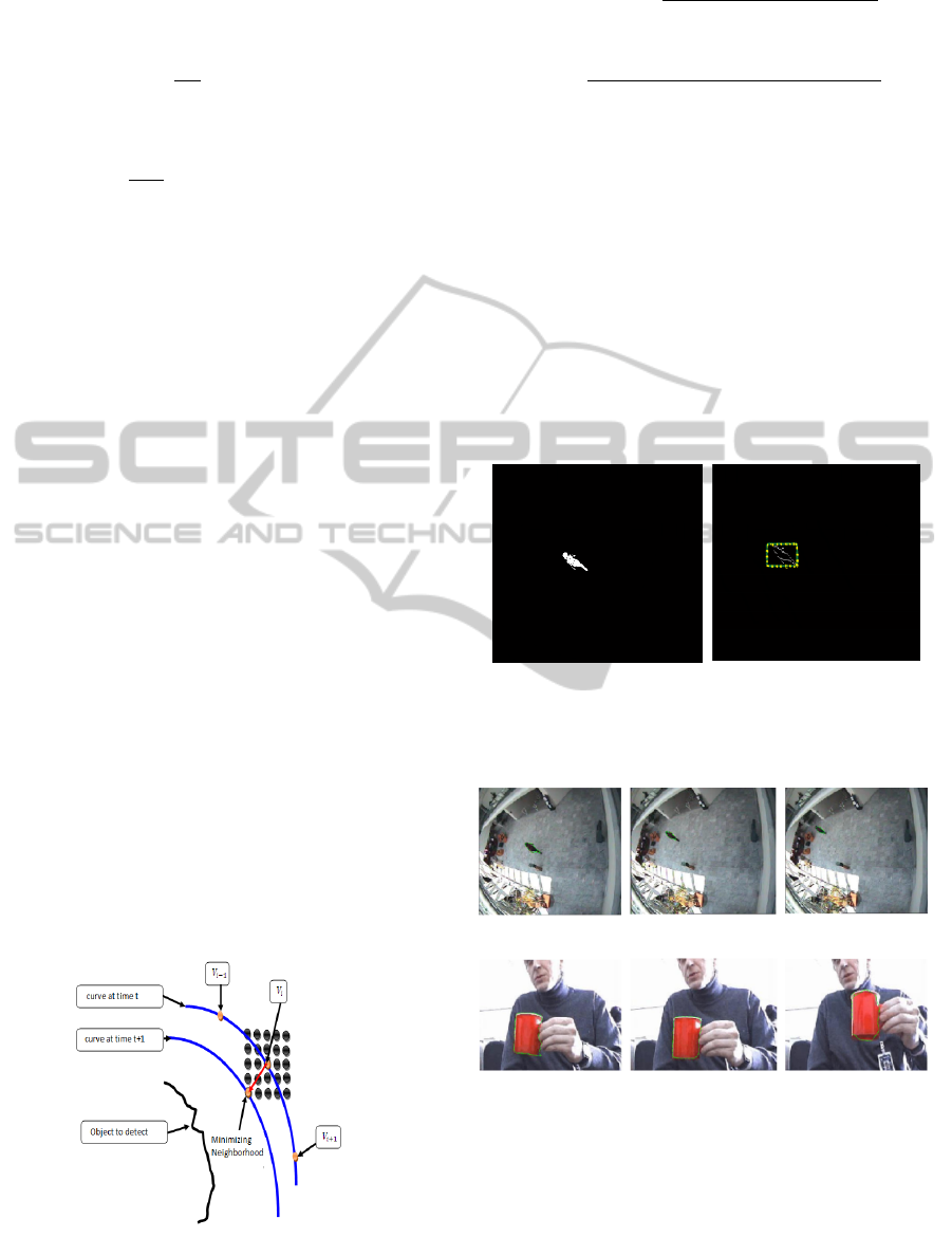
Figure 2: Contour evolution.
E
cont
=
D
Avg
−
q
(x
i
− x
i−1
)
2
− (y
i
− y
i−1
)
2
(9)
E
curv
=
q
(x
i−1
+ 2x
i
+ x
i+1
)
2
− (y
i−1
+ 2y
i
+
y
i+1
)
2
(10)
The minimization process is developed to find itera-
tively the minimum index image gradient value in the
neighbourhood of each contour point (Figure. 2).
3.3 Results
We propose two examples to test the snake method
for tracking in perspective images. The ”WALK”
sequence(90 frames) and the ”CUP” sequence (60
frames). The first operation is to detect our object.
Background subtraction illustrated in figure.3
(a) Object detected by back-
ground substraction
(b) Initialization contour
Figure 3: Object detection and initialization contour.
(a) Object Tracking (walk sequence)
(b) Object Tracking (Cup sequence)
Figure 4: Object Tracking.
We choice α = 1.2, β = 1, and γ = 1.2. The ob-
tained results figure. 4 correspond perfectly to our
needs. With ”WALK” sequence, We obtained a detec-
tion time for the first frame 1.05 seconds and a mean
tracking time for other images 0.43s. Using ”CUP”
sequence we obtained a detection time of 0.51s and
0.41s time tracking. Given that the processing was
ObjectsTrackinginCatadioptricImagesusingSphericalSnake
437
done in an environment of Pc Core2duo 2.4G, 2G of
memory and 1G graphics.
Object tracking in perspective images gave good re-
sults for each image of the sequence through the ac-
tive contours. On the other side, in this method we
have limitations. We find on the one hand the choice
of parameters α, β, and γ, we have to solve many ex-
periments that require time. On the other hand, we
can keep the error if it occurred in the object tracking
because the position of contour points is saved.
4 OMNIDIRECTIONAL SNAKE
FOR TRACKING
The adapted tracking in omnidirectional images
amounts to adapt the process in perspective images.
We include the various operators developed in this al-
gorithm.
• The Gaussian filter is applied to reduce the noise
in images sequence.
• The subtraction background algorithm used in ob-
ject detection.
• The energies minimization in the spherical neigh-
bourhood of each contour points used for spheri-
cal tracking in spherical omnidirectional images.
4.1 Spherical Gaussian Filtering
We introduce the Gaussian function on the sphere as
follows (Antoine and Vandergheynst, 1999) reads:
G
s
(θ, ϕ) =
1
2 σ
2
e
−
1
2 σ
2
(
cotg
2
(
θ
2
)
t
)
(11)
We apply a Gaussian filter based on the point rota-
tion defined in (Daniilidis et al., 2002) for the omni-
directional image smoothing. In the sphere, we ap-
plied a convolution (Equation.(13)) between a spheri-
cal Gaussian (Equation.(11)) and the spherical image
I. We embed the sphere in R
3
and write an element
P(cos(ϕ) sin(θ), sin(ϕ) sin(θ), cos(θ)). Rotations in
R
3
will be parametrized by Euler angles such that any
R ∈ SO(3) will be written as :
R = R
z
(ϕ) R
y
(θ) R
x
(ψ) (12)
where R
y
and R
z
denote rotation about the y, and z
axis, respectively. The convolution will be defined as:
(I ∗ G
s
)(P) =
Z
f (R n
0
)g
R
−1
P
dR (13)
n
0
= (0, 0, −1) is half sphere south pole, and dR =
sin(θ)dθ dϕ.
4.2 Spherical Object Tracking
4.2.1 Spherical Neighbourhood
We defined the new spherical neighbourhood:
N
s
=
|δθ|≤
1
N
, 2π −
1
M
≤ δϕ ≤
1
M
(14)
N et M are the neighbourhood orders.
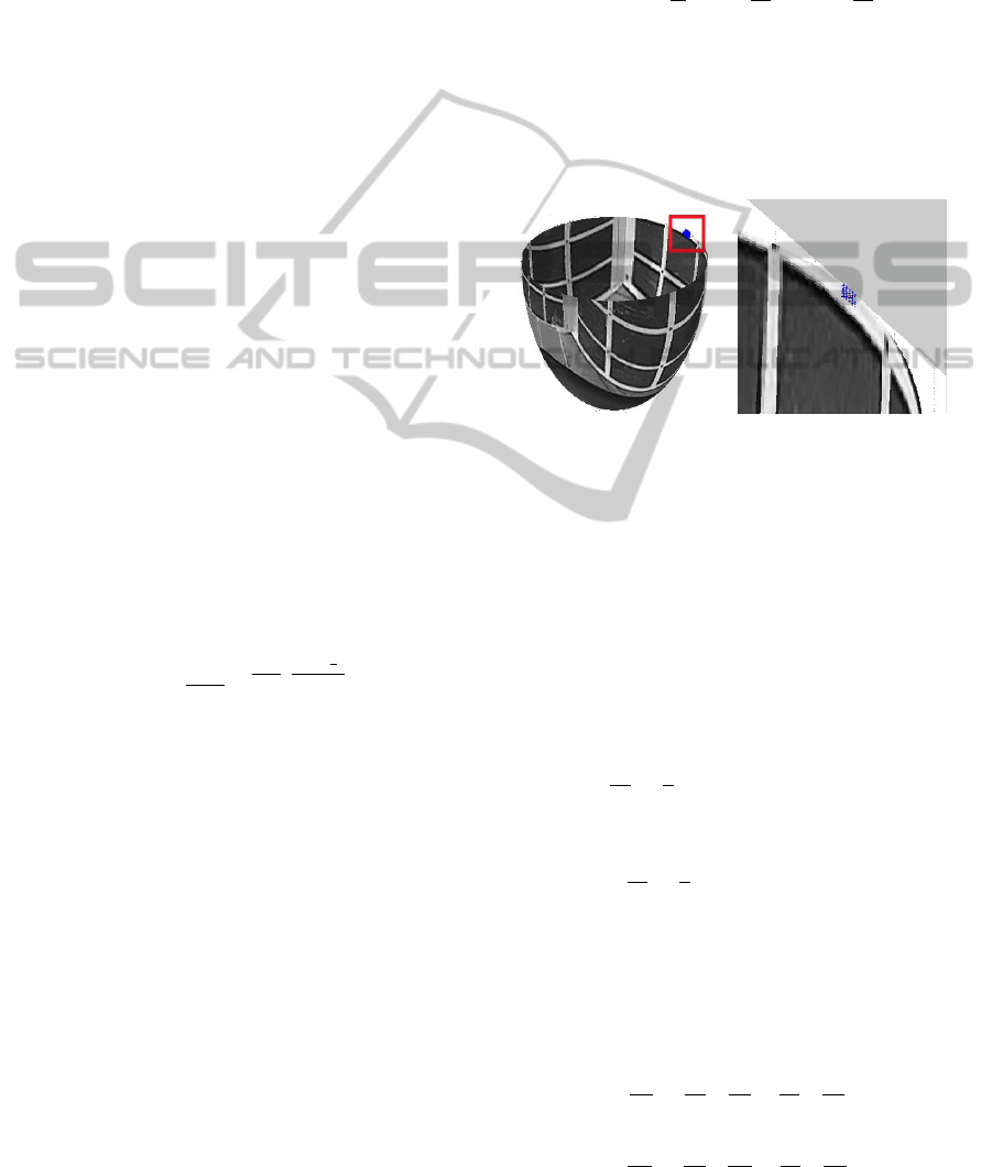
In our algorithm, we defined the neighbourhood de-
fined by size block 5. That means each contour point
has 25 neighborhood. The shape of the spherical
block is represented in figure. 5.
Figure 5: Example of spherical neighbourhood.
4.2.2 Spherical Gradient
In our algorithm, we defined a spherical gradient (im-
age, continuity, and curvature) For the image energy,
we apply a spherical contour detection by Sobel filter
in the sphere.
first, Sobel proposed filter based on using the mask
filtering (Geyer and Daniilidis, 2001) in u and v is
defined by:
∂I
∂u
≈
1
4
−1 −2 −1
0 0 0
1 2 1
(15)
∂I
∂v
≈
1
4
−1 0 1
−2 0 2
−1 0 1
(16)
In practice, Daniilidis in (Daniilidis et al., 2002), have
effects a variables change defined by:
I (θ, ϕ) = I(u (θ, ϕ), v (θ, ϕ)) (17)
∂I
∂θ
=
∂I
∂u
∗
∂u
∂θ
+
∂I
∂v
∗
∂v
∂θ
(18)
∂I
∂ϕ
=
∂I
∂u
∗
∂u
∂ϕ
+
∂I
∂v
∗
∂v
∂ϕ
(19)
VISAPP2014-InternationalConferenceonComputerVisionTheoryandApplications
438
where u and v are defined in Equation.(2). The spher-
ical gradient can be expressed as : Equation.(20):
(
−→
∇I
s
= (
∂I
∂θ
,
1
sin(θ)
2
∗ (
∂I
∂ϕ
))) (20)
where I
s
is the spherical image.
4.2.3 Spherical Energies
From Equation.(20), energie can be expressed based
on spherical point.
The external or image energy is presented by the nor-
malized spherical gradient in θ and ϕ. This energie is
expressed in Equation.(21), where the result is illus-
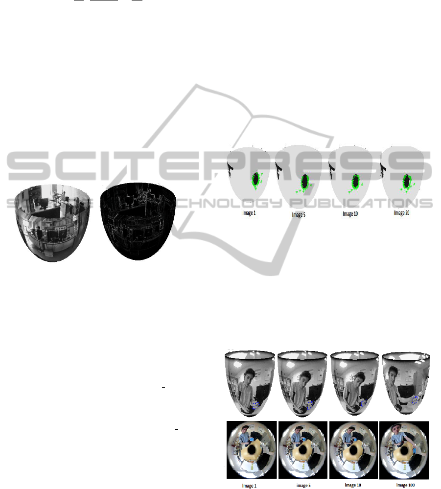
trated in figure.6.
E
xtS
= E
gradS
=
Z
1
0
∇ I
s
k
V (S)
k
2
ds (21)
where V (S) = Ps(θ,ϕ).
Figure 6: Spherical Sobel (image energy).
Thus, we calculate spherical continuity and curvature
energies by a distance between contour points in the
half-sphere. This distance have determined by a 3D
euclidean distance in linear case because points are
close together using (in continuity energy case) the
average distance D
A
vg (Wiliams and Shah, 1992).
E
ctS
= |D
A
vg−((x
i
−x
i−1
)
2
−(y
i
−y
i−1
)
2
−(z
i
−z
i−1
)
2
)|
1
2
(22)
E
cvS
= ((x
i−1
+2x
i
+x
i−1
)
2
−(y
i−1
+2y
i
+y
i−1
)
2
−(z
i−1
+2z
i
+z
i−1
)
2
)
1
2
(23)
The Total energy defined in Equation.(24).
E
TotS
=
N
∑
i=1
(a ∗ E
pi
intS
+ b ∗ E
pi
extS
) (24)
The total energy minimization is formed in the neigh-
bourhood of each point of the contour. The neigh-
bour that minimizes the energy will be the next con-
tour point initial.
Ei
min
= Arg
min
(Ei
TotalS
(Pi(θ, ϕ))
N
s
) (25)
5 EXPERIMENTS AND RESULTS
To illustrate our contribution, we present the spherical
active contour on synthetic and real images. we’ll just
present the snake on the space of the spherical image,
since no other comparison can be made in our context.
5.1 Spherical Tracking: Synthesis
Images
We apply edge detection to initialize the points con-
tours from the outline of our object before apply the
minimization algorithm. In figure.7, we show object
tracking (spherical form) in images obtained using
POV-RAY software.
Figure 7: Tracking result -1-.
5.2 Spherical Tracking: Laboratory
Images
We obtained the result in ”Cata” sequence (780 im-
ages) figure 8 and 9. We show the catadioptric
and spherical image equivalent with spherical points
snake in object (card) tracking.
Figure 8: Tracking result -2-.
We conclude from the obtained results, that using of
active contours in tracking gives results promoting in
terms of edge detection and tracking such as conver-
gence of the algorithm in minimization of the energy
functional. (For the minimization algorithm.
ObjectsTrackinginCatadioptricImagesusingSphericalSnake
439

Figure 9: Tracking result -3-.
6 CONCLUSIONS
In our spherical tracking, a first object detection based
on background subtraction is applied to the starting
image. The minimization algorithm to the others im-
ages is applied. Using the adapted process and projec-
tion approach, the object contour is perfectly tracked
in the equivalent half sphere. The tracking time is
about 0.41 seconds and the detection consumes 0.34
seconds. We conclude from the obtained results, that
using of snake in tracking gives results promoting in
terms of edge detection and tracking such as the al-
gorithm convergence in minimization of the energy
functional. For the minimization algorithm, we want
to specify two stop criterion, corner number and im-
age energy threshold. The corner conditions are veri-
fied when the coefficient of rigidity β is equal to zero.
Using snake in tracking is the most used approachs in
video surveillance due to the extensibility and ability
of recognition for both object shape and orientation.
In addition, it’s adapted well to object size changes in
catadioptric image. However, this method is limited
mainly by the choosing of the energy parameters and
also occurred error by the minimization algorithm.
REFERENCES
Mikhael Kass, Andrew Witkin, Demetri terzopoulos
”Snakes: Active Contour Models”, International
Journal of Computer Vision, page :321−331(1988).
Lucas, B. D., and Kanade, T. ”An iterative image registra-
tion technique with an application to stereo vision”.
Proc. Int. Joint Conf. on Artificial Intelligence, Van-
couver, Canada, 1981, pp. 674−859.
Comaniciu, D., Ramesh, V., and Meer, P. ”Real-time track-
ing of non-rigid objects using mean shift”. Proc. IEEE
Conf. on Computer Vision and Pattern Recognition,
Hilton Head Kland, SC, USA, 2000, pp. 142−149.
Isard, M., and Blake, A. ”Condensation conditional density
propagation for visual tracking”, Int. J. Comput. Vis. ,
1998, 28, (1), pp.5−28.
Donna J. Wiliams, Mubarak Shah. ”A Fast Algorithm For
Active Contours and Curvature Estimation”,CVGIP
:image understanding, Vol.55, No.1, January, pp.14-
26,1992.
Geyer C., Daniilidis K. , ”Catadioptric Projective Geome-
try”, International Journal of Computer Vision, 2001.
David G. Lowe, ”Distinctive Image Features from Scale-
Invariant Keypoints”, International Journal of Com-
puter Vision, vol. 60, no 2, 2004, p. 91-110, 2010.
F. Rameau, D. Sidibe, C. Demonceaux, D. Fofi. ”Visual
Tracking with Omnidirectional Cameras : An Effi-
cient Approach”. IET Electronic Letters, Vol.47, Issue
21, pp.1183-1184, October 2011.
N. Ikoma,R. Yamaguchi, H. Kawano, and H. Maeda.
”Tracking of Multiple Moving Objects in Dynamic
Image of Omnidirectional Camera Using PHD Filter”.
Journal of Advanced Computational Intelligence and
Intelligent Informatics Vol.12 No.1, 2008.
David Hurych, Karel Zimmermann, Tomas Svoboda. ”Fast
learn able Object tracking and detection in high-
resolution omnidirectional images”, visapp2011.
K. Daniilidis, A. Makadia, T. Bulow, ”Image processing
in catadioptric planes: Spatiotemporal derivatives and
optical flow computation”, Omnidirectional Vision,
Third Workshop on, 3-10 2002.
Simon Baker and Shree K. Nayar, ”Single Viewpoint Cata-
dioptric Cameras,” Panoramic Vision: Sensors, The-
ory, Applications, Ryad Benosman and Sing Bing
Kang, ed., Springer-Verlag, 2001.
J.-P. Antoine and P. Vandergheynst. ”Wavelets on the 2-
sphere: A group-theoretical approach. Applied and
Computational Harmonic Analysis”, 7:262291, 1999.
Guillaume Caron, El Mustapha Mouaddib, Eric Marchand.
”3D model based tracking for omnidirectional vision:
A new spherical approach”,In International Journal
on Robotics and Autonomous Systems 60, 10561068,
2012.
C. Mei, E. Malis, S. Benhimane, P. Rives. ”Constrained
Multiple Planar Template Tracking for Central Cata-
dioptric Cameras.” In British Machine Vision Confer-
ence, Edinburgh, United Kingdom, September 2006.
VISAPP2014-InternationalConferenceonComputerVisionTheoryandApplications
440
