
Obstacle and Planar Object Detection using Sparse 3D Information for a
Smart Walker
S´everine Cloix
1,2
, Viviana Weiss
2
, Guido Bologna
2
, Thierry Pun
2
and David Hasler
1
1
Vision Embedded Systems, CSEM SA, Jaquet Droz 1, Neuchˆatel, Switzerland
2
Computer Science Department, University of Geneva, Route de Drize 7, Carouge, Switzerland
Keywords:
Binocular Stereo Vision, Sparse 3D Map, Obstacle Detection, Object Detection, Boosting, Elderly Care.
Abstract:
With the increasing proportion of senior citizens, many mobility aid devices have been developed such as the
rollator. However, under some circumstances, the latter may cause accidents. The EyeWalker project aims
to develop a small and autonomous device for rollators to help elderly people, especially those with some
degree of visual impairment, avoiding common dangers like obstacles and hazardous ground changes, both
outdoors and indoors. We propose a method of real-time stereo obstacle detection using sparse 3D information.
Working with sparse 3D points, in opposition to dense 3D maps, is computationally more efficient and more
appropriate for a long battery-life. In our approach, 3D data are extracted from a stereo-rig of two 2D high
dynamic range cameras developed at the CSEM (Centre Suisse d’Electronique et de Microtechnique) and
processed to perform a boosting classification. We also present a deformable 3D object detector for which the
3D points are combined in several different ways and result in a set of pose estimates used to execute a less
ill-posed classification. The evaluation, carried out on real stereo images of obstacles described with both 2D
and 3D features, shows promising results for a future use in real-world conditions.
1 INTRODUCTION
To help in their mobility, millions of senior citizens
use mobility aids such as rollators. But these devices
may fail to help or, even worse, can cause accidents.
This occurs when the user misjudges the nature or
the extent of some obstacles, which can happen in
any kind of familiar or unknown environments. Vari-
ous prototypes of “intelligent walkers”, developed to
answer these issues, are usually motorized and pro-
grammed to plan routes and to detect obstacles with
active or passive sensors. However, such aids are usu-
ally unaffordable or at a prototype level, hence, the
user might be reluctant to such complex systems. Fi-
nally, their use is often limited to indoor situation due
to their weight and their short battery life.
Unlike the current trend, the EyeWalker project
aims to develop a low-cost, ultra-light computer
vision-based device for users with mobility problems.
It is meant to be an independent accessory that can be
easily fixed on a standard rollator and with a daylong
autonomy. Our device will warn users of potentially
hazardous situations or help to locate a few particu-
lar objects in miscellaneous environments and under
widely varying illumination conditions. The users we
initially target are elderly persons that still live rela-
tively independently. To meet the requirement of de-
signing a device that helps rollator users in their daily
activities, we work on ground change and obstacle de-
tection. The former is built on (Weiss et al., 2013) and
the latter is based on (Cloix et al., 2013). We present
obstacle and object detection methodsbased on boost-
ing classification using sparse 3D data. Our 3D sparse
maps are built from stereo images captured from two
high dynamic range cameras that can handle bright
illumination, indoors or outdoors.
This paper is organized as follows: Section 2 de-
scribes relevant examples related to the state-of-the-
art in stereo computer vision; Section 3 describes our
approach; the hardware setup used for the evaluation
of our detectors, the discussed results and the future
work are detailed in Section 4 followed by the con-
clusion in Section 5.
2 RELATED WORK
The definition of an obstacle highly depends on the
domain the detector is developed for. For driving as-
sistance, an obstacle will be any object standing on
292
Cloix S., Weiss V., Bologna G., Pun T. and Hasler D..
Obstacle and Planar Object Detection using Sparse 3D Information for a Smart Walker.
DOI: 10.5220/0004661602920298
In Proceedings of the 9th International Conference on Computer Vision Theory and Applications (VISAPP-2014), pages 292-298
ISBN: 978-989-758-004-8
Copyright
c
2014 SCITEPRESS (Science and Technology Publications, Lda.)

a dominant ground surface (Broggi et al., 2011). In
the field of health care rehabilitation, it would rather
be a static or moving object in the walking path at
any height from the ground to head-level (Ong et al.,
2013).
The domain of application also leads to the choice
of the sensors. In robotics, devices mainly devel-
oped for an outdoor usage to scan the frontal scene
are equipped with ultrasound, laser or radar (Lacey
and Rodriguez-Losada, 2008). Range finders allow
extracting a dense depth map of the captured scene.
But this equipment is expensive and power consum-
ing, which is of main concern in health care assistance
field, not to mention the weight. It justifies why stereo
vision (Rodr´ıguez et al., 2012) or IR sensors are more
employed (Ong et al., 2013).
As far as computer vision is concerned, multi-
view vision is a topic in which intensive research
has been conducted for the last half century (Seitz
et al., 2006). It allows 3D reconstruction thanks to
the hardware performance enabling real-time applica-
tions. Commercial cameras like the Bumblebee2
1
and
the Microsoft Kinect
2
are also the main catalysers of
this research growth by providing dense 3D maps.
Focusing on binocular vision, several methods
were developed to detect obstacles such as digital ele-
vation map (DEM) (Oniga and Nedevschi, 2010) and
occupancy grids (Rodr´ıguez et al., 2012) (Perrollaz
et al., 2010). Stereo information is also often used for
distance computation after an obstacle is detected in
one of the two images (Jos´e et al., 2011). Moreover a
majority of the most recent stereo vision-based obsta-
cle detectors use dense 3D maps to cope with stereo
mismatch. Regarding sparse 3D maps, (Toulminet
et al., 2006) extract the desired 3D features to detect
vehicles in a very constrained environment given by
the application domain. This lets the sparse 3D in-
formation usage barely exploited to detect everyday
obstacles with various sizes and shapes.
The contribution of this paper lies in the use of
sparse 3D information to develop a novel strategy of
obstacle and object detection by boosting classifica-
tion. Extracting a few stereo data, computationally
more efficient, allows the obstacle detector to run in
real-time in any illumination conditions and for a long
time thanks to our low power-consuming cameras.
3 METHODS
We want to implement two binary classification-based
detectors, one for general obstacles and one for spe-
1
http://ww2.ptgrey.com/stereo-vision/bumblebee-2
2
http://www.xbox.com/en-US/kinect
cific objects. The former is described in Section 3.2
and the latter is explained in Section 3.3. Since a 3D
point cloud lets a priori suppose the presence of an
obstacle, the detectors use information from left and
right pictures to compute sparse 3D maps. The imple-
mented classification algorithm is the AdaBoost (Fre-
und and Schapire, 1997) that generates a linear com-
bination of weak classifiers.
3.1 Stereo Correspondence
In sparse 3D maps, only very few points have their
distance known. Those points are usually with spe-
cific characteristics like feature points (Bay et al.,
2008) or corners (Harris and Stephens, 1988). The
stereo correspondence can be carried through various
methods among which there are cross-correlation or
descriptor matching, the latter being the one we chose
to meet real-time and battery-life requirements.
Knowing the intrinsic and extrinsic parameters of
the stereo-rig obtained at the calibration phase and the
disparity, i.e. x
L
− x
R
, with x
L
and x
R
the respective x-
coordinate of the observed point in the left and right
undistorted and rectified pictures, the three space-
coordinates of a point can be computed. To extract
a 3D point cloud from each pair of pictures, we pro-
ceed as follows: (i) corners are detected (Harris and
Stephens, 1988) in both left and right pictures, pre-
liminarily equalized and Gaussian blurred; (ii) they
are described with BRIEF descriptor (Calonder et al.,
2010) and matched using the Hamming distance; (iii)
lens distortion is taken into account in an intermediate
step to compute the 3D coordinates of each corner.
3.2 Obstacle Detection
The first family of features employed to describe the
cloud of points is a 3D box (Figure 1, top left). This
feature, defined by six parameters, the three location
coordinates and the dimensions, returns the number
of points inside the box.
The second family of features computes the dif-
ference of luminance in defined areas between the left
picture and the right picture (Figure 1, top right). The
parameters are the size of the region, the location in
the left image and the shift, ∆x, on the x-axis of the lo-
cation in the right image. The epipolar-constrained ar-
eas thus defined allow computing the sum of the pixel
values.
The last family of features, depicted in Figure 1
(bottom), is similar to the Haar filters used by (Viola
and Jones, 2004). In our case, the filters are defined
by a black zone around the centre of the left image.
Thus the parameters to define a feature are its shape
ObstacleandPlanarObjectDetectionusingSparse3DInformationforaSmartWalker
293

Figure 1: Visualisation of the obstacle detector features.
(top left): a 3D box in which we count the number of points;
(top right) a pair of areas for the computation of difference
of luminance; (bottom) Haar filter with the third shape de-
scribed in the sketch on the right.
(black square, horizontal or vertical band), the size of
the patch, the ratio of the central zone to the patch and
the location of the patch in the image.
3.3 Planar Object Detection
We aim at detecting planar objects in a 2D image by
combining the 3D points in several different ways, re-
sulting in a set of pose estimates for a less ill-posed
classification. We assume the object is represented by
a 3D generic and normalized model M. From the 3D
point cloud, we estimate a list, Θ, of poses, θ ∈ Θ, of
the object. A feature family, F, is defined in the model
space: the pose estimate allows the features f ∈ F de-
fined on the model to “stick” to objects of any shape
and position in the scene, as depicted on Figure 2.
The planar object model used is a front facing
square with a defined side size, ζ, and described
by a triplet of ordered corners {P
0
(ζ,0,0); P
1
(0,0,0);
P
2
(0,ζ,0)}. For N matched corners extracted as de-
scribed in Section 3.1, the number of triplets is O(N
3
).
To reduce this number of pose estimates, we use the
FLANN algorithm (Muja and Lowe, 2009) to keep
triplets that have two points horizontally aligned and
two vertically aligned. The pose estimation matrix is
extracted by matching P
i
to p
i
, i = [0;1;2] like shown
in Figure 2.
Three families of features were defined as follows:
(i) the cosine of the angle defined by the three points;
(ii) the scale, over X, Y or the ratio X/Y; (iii) the
Haar-like filters. The latter is defined by the follow-
Figure 2: Model correspondence to a triplet of points that
represents a pose of a cabinet door, with a deformable Haar-
like feature, the model being a front facing square.
Figure 3: Haar like feature for the detection of the cabinet
door.
ing parameters, (a) the filter: eight different shapes
that represent the edges and the corners, shown in Fig-
ure 3; (b) the size of the filter; (c) the position in the
model (X,Y) in order to localize the scanning window
around the estimated pose. The return value uses the
pixel values of the filter corners from the left picture:
H =
∑
0≤i≤3
s
i
× p
i
(1)
where s
i
is the sign defined by the shape of the fil-
ter (+ if black, − if white) and p
i
the pixel value of
corner i.
4 EXPERIMENTS & DISCUSSION
The evaluation of the methods are performed on static
stereo pictures acquired with an experimental setup
detailed in Section 4.1 in order to measure the perfor-
mance of our general obstacle and object detectors.
4.1 Hardware Setup
The rollator is equipped with a calibrated stereo-rig
of two cameras developed by the CSEM, called icy-
Cams. The 20 cm-baseline rig is tilt at 20 degrees
from the horizon and fixed on the rollator at 67 cm
from the ground. These cameras are characterized by
their high dynamic range and their logarithmic com-
pression that allows coping with bright illumination.
Their power consumption is very low, which is of
great importance since the final device has to have a
battery life of one day. The focal lengths are equal
to 3.8 mm and the resolution is 320x240 pixels, 14e-
6 m per pixel, resulting in a vertical view angle of
47.7 degrees (Figure 4). The cameras were connected
Figure 4: Actual hardware setup allowing viewing obstacles
at less than two meters and at the waist-level up to head-
level.
VISAPP2014-InternationalConferenceonComputerVisionTheoryandApplications
294

to a laptop computer through a usb-powered Ethernet
switch for the acquisition of stereo frames in various
environments.
4.2 Obstacle Detection
To evaluate the performance of our binary classifier,
experiments were conducted on a data set of eleven
types of obstacles (cf. Figure 5). The training set
was composed of 3107 pairs of pictures. The test
set had 732 pairs of frames of similar obstacles taken
in places different from the training set. The images
were taken from real scenes, both indoors and out-
doors, with a frame rate of approximately 7 f ps and
walk speed of about 0.5 m/s. The two classes are de-
fined as follows: a frame is labelled positive if there
is an obstacle on the pathway at less than two meters
from the cameras; the frame is negative otherwise.
The indoor obstacles are: (i) a cupboard; (ii) a desk
chair; (iii) a corridor wall; (iv) a white board; (v) a
doorframe not centered on the path; (vi) a coffee ma-
chine in a kitchen; (vii) a dish-washer. The outdoor
obstacles are: (i) a bush; (ii) a street lamp pole; (iii)
a parking fence; (iv) a road sign. The non-obstacle
data are made of the pictures of long corridors, street,
office and kitchen views.
For the sake of comparison with our approach, we
implemented a baseline detector that counts the num-
ber of points into a warning area. The decision was
made according to the number of points present into a
frontal cube centered on the path at 0.5 meter from
the cameras, 1.5 meter deep, 0.8 meter high and a
width varying between 0.5 and 0.8 meter. The results
demonstrate it is not possible to have more than 75%
true-positive rate without less than 30% of false alarm
Figure 5: Samples of left-camera pictures for the obstacle
data set:(first two rows) pictures labelled as negative (no
obstacle or above two meters from the cameras); (last two
rows) pictures labelled as positive,(obstacle is at less than
two meters from the cameras).
(cf. Figure 6).
The obstacle boosting classifier was evaluated by
generating four kinds of classifiers: three were trained
with only one of the feature families described in Sec-
tion 3.2 and one with all the families. The Figure 7
shows the average performance of each feature fam-
ily independently and of the three families together.
The 3D box family presents a better performance
than the other features and the simple detector. Be-
sides, the addition of the other features enables a sig-
nificant improvement (true-positive rate from 69.8%
to 75.4% at 10% false-positive rate). Even some of
the classifiers generated with all the feature families
give more than 83% true-positive rate for less than
10% false-positive rate. The 3D boxes return value
actually represents a density of points, which is ex-
pected to be high for positive frames, i.e. with an
obstacle. The resulting weak classifier being char-
acterised by its threshold, optimized at the training
phase, it explains why this boosting classifier per-
forms better than the basic detector.
For the second family of features, the return value
is the difference of luminance. Such features should
return small scores when the two patches cover the
same object. The variability in the distances of the
training obstacles could explain the difficulty to the
training framework to choose the best luminance fea-
tures.
Finally, the Haar filter score should be high when
the filter is centered on a dark or light patch of colour
representing an obstacle. Here as well, the actual per-
formance of such a detector can be explained by the
variability of the patch size and shape in the train-
ing set. As a result, the classifiers composed of only
one of the two latter families perform worse than the
one of 3D boxes. A solution would be to grow the
database for a better distribution, especially when we
see that the classifier built with all the feature families
performs better than the one of 3D boxes.
The tests were carried out offline on a 2.93
GHz/Linux x86-64 desk computer. The actual pro-
gram uses a single processor. In these conditions the
detection took 244 ms. This computation time cor-
responds to 4 f ps and can be improved by code op-
timisation and by the use of parallelization for com-
puting each weak classifier score. On an embedded
system the use of a GPU would improve the time per-
formance.
4.3 Cabinet Door Detection
After having detected obstacles with a certain degree
of accuracy, another user requirement is to detect spe-
cific objects with the use of vision features provided
ObstacleandPlanarObjectDetectionusingSparse3DInformationforaSmartWalker
295

to a boosted classifier. To evaluate the approach, the
planar object chosen is a kitchen cabinet door. Pre-
liminary experiments are performed on a data set of
stereo pictures taken in a kitchen show room (Fig-
ure 8). The positives are annotated with triplets. Un-
known zones are also marked. From this annotation,
N
S
negatives per pair of images are extracted by the
triplet detector and according to the distance from the
positive samples and the unknown zones. The train-
ing is done with 80% of the data set, the remaining
20% being reserved for the test, randomly selected.
The annotation is rigid in a sense that the triplet has
to represent the door so that the vertical segment is on
the hinge.
Figure 9 shows the performance (66.7% true-
positive rate at 10% false-positive rate) and high-
lights several limitations of the pose estimator chosen.
Firstly, the actual pose estimator is not robust to the
lack of robustness of the corner detection-matching
step. The insufficient precision of the corner detector
and its parametrization depends on the distance to the
object and also on the picture quality. The latter was
lowered by the poor illumination of the scenes and the
cameras resolution. When the desired 3D corners are
not detected (because not detected on one or both pic-
tures or not matched and thus discarded), the object
is not localized. As a result, about 80% of the tested
doors were detected prior classification. Secondly, we
have to look at the way negative samples used for the
classifier training were extracted. Any triplet that has
at least one point far from the ones of a positive triplet
is considered negative. As a consequence, a negative
triplet can have up to two points that also belong to a
positive triplet. Thus the feature vector of the nega-
tive sample can be partially similar to the one of the
positive sample.
The ambiguity on closed doors is important since
kitchens include several doors on the same plane. To
reduce this ambiguity, new experiments were con-
ducted on opened doors. The annotation is made
broader to make a rotation-invariant classifier: each
door is annotated once and the other seven triplets
defining the door are generated and added into the
training data set. By focusing on opened doors,
Figure 6: Performance of the basic detector: (left) ROC
curve (right); precision-recall curve.
Figure 7: Performance of the boosting obstacle detector
built with the 3D box features only (red),with the Haar fil-
ter features only (green), with the luminance difference fea-
tures only (blue), with all the features (purple): (left) ROC
curves; (right) Precision-recall curves.
the performance improved: the localisation rate went
from 85.4% to 96.1% and the true-positive rate from
66.5% to 83% at 10% false-positive rate.
From a point cloud, the complexity makes the
number of hypotheses too big, leading to an unsat-
isfying false-positive rate and a very low precision.
Despite the actual pose estimator, the classifier gives
good results. However, the problem is complex be-
cause of the number of tests (about 150’000 per pair
of images) required for the localisation of a potential
door, the number of degrees of freedom regarding the
orientation estimation and the significant appearance
variation (size, presence of handle or not, texture).
4.4 Future Work
The main focus is to improve the current general ob-
stacle detector recall and precision. To do so, we will
optimize the stereo matching by improving the image
pre-processing in order to reduce the noise stereo mis-
matching introduces. The actual experiments being
carried out on static stereo images, we intend to intro-
duce temporal information such as Kalman filters or
optical flow to filter the 3D information. Indeed, we
suppose the knowledge of past frames can improve
the actual results. The data set size revealing the ef-
fect of the variability issue on the classification, it has
to be increased.
Last but not least, the object detector evaluation
results suggest reducing the complexity of the prob-
lems encountered with the cabinet doors. The main
issues to solve are twofold: (i) to be able to detect all
Figure 8: Samples of the data set of cabinet doors.
VISAPP2014-InternationalConferenceonComputerVisionTheoryandApplications
296
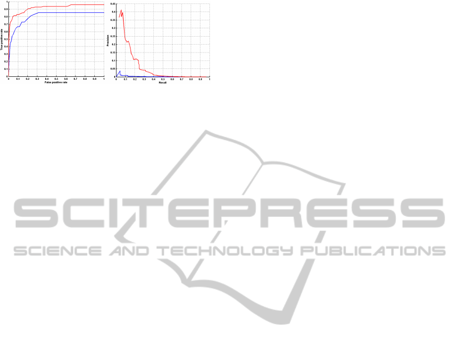
Figure 9: Performance of the boosting door detector built
with the Haar-like features: (blue) Performance of on all
doors; (red) Performance of on opened doors; (left) ROC
curves; (right) Precision-recall curves.
the desired corners among a few to limit the number
of tests required to meet real-time conditions; (ii) re-
view the hypotheses to restrict the variability of the
category defining cabinet doors.
5 CONCLUSIONS
To help rollator users to avoid common dangers with a
computer vision-based device, we introduced two de-
tectors depending on features including 3D and stereo
data: one for general obstacles located at waist-level
and above, and a second one for specific objects. Both
detectors are based on boosting classification. The
obstacle detector mixes three kinds of features among
which two require stereo information: 2D Haar fil-
ters, 3D boxes and luminance comparison between
the stereo pictures. The experiments show promis-
ing results that can be improved by the future work
mentioned in Section 4.4. The deformable 3D object
detector, mainly composed of Haar-like features, re-
mains an interesting strategy, despite the evaluation
results, the actual pose estimator having to be thought
over to make the binary classifier more robust and
faster.
ACKNOWLEDGEMENTS
This project is supported by the Swiss Hasler Foun-
dation Smartworld Program, grant Nr. 11083. We
thank our end-user partners: the FSASD, Fondation
des Services d’Aide et de Soins Domicile, Geneva,
Switzerland; EMS-Charmilles, Geneva, Switzerland;
and Foundation “Tulita”, Bogot´a, Colombia. The cab-
inet door database was made in Schaer Cuisines SA,
Neuchˆatel, Switzerland.
REFERENCES
Bay, H., Ess, A., Tuytelaars, T., and Van Gool, L. (2008).
Speeded-up robust features (surf). Computer vision
and image understanding, 110(3):346–359.
Broggi, A., Buzzoni, M., Felisa, M., and Zani, P. (2011).
Stereo obstacle detection in challenging environ-
ments: the VIAC experience. In International Con-
ference on Intelligent Robots and System, pages 1599–
1604, San Francisco, CA, USA. IEEE Computer So-
ciety.
Calonder, M., Lepetit, V., Strecha, C., and Fua, P. (2010).
Brief: binary robust independent elementary features.
In Proceedings of the 11th European conference on
Computer vision: Part IV, pages 778–792, Berlin,
Heidelberg. Springer-Verlag.
Cloix, S., Weiss, V., Guido, B., Pun, T., and Hasler, D.
(2013). Object detection and classification using
sparse 3d information for a smart walker. In Swiss Vi-
sion Day 2013, Poster Session, ETH Z¨urich, Switzer-
land.
Freund, Y. and Schapire, R. E. (1997). A decision-theoretic
generalization of on-line learning and an application
to boosting. Journal of Computer and System Sci-
ences, 55(1):119–139.
Harris, C. and Stephens, M. (1988). A combined corner and
edge detector. In Alvey vision conference, volume 15,
page 50. Manchester, UK.
Jos´e, J., Farrajota, M., Rodrigues, J. M., and du Buf,
J. (2011). The smartvision local navigation aid for
blind and visually impaired persons. Available at
http://hdl.handle.net/10400.1/892.
Lacey, G. and Rodriguez-Losada, D. (2008). The evolution
of guido. Robotics & Automation Magazine, IEEE,
15(4):75–83.
Muja, M. and Lowe, D. G. (2009). Fast approximate nearest
neighbors with automatic algorithm configuration. In
International Conference on Computer Vision Theory
and Application, pages 331–340. INSTICC Press.
Ong, S. K., Zhang, J., and Nee, A. Y. C. (2013). Assistive
obstacle detection and navigation devices for vision-
impaired users. Disability and Rehabilitation: Assis-
tive Technology, pages 1–8.
Oniga, F. and Nedevschi, S. (2010). Processing dense stereo
data using elevation maps: road surface, traffic isle,
and obstacle detection. Vehicular Technology, IEEE
Transactions on, 59(3):1172–1182.
Perrollaz, M., Spalanzani, A., and Aubert, D. (2010). Prob-
abilistic representation of the uncertainty of stereo-
vision and application to obstacle detection. In In-
telligent Vehicles Symposium (IV), 2010 IEEE, pages
313–318. IEEE.
Rodr´ıguez, A., Yebes, J. J., Alcantarilla, P. F., Bergasa,
L. M., Almaz´an, J., and Cela, A. (2012). Assisting
the visually impaired: Obstacle detection and warning
system by acoustic feedback. Sensors, 12(12):17476–
17496.
Seitz, S. M., Curless, B., Diebel, J., Scharstein, D., and
Szeliski, R. (2006). A comparison and evaluation of
multi-view stereo reconstruction algorithms. In Con-
ference on Computer Vision and Pattern Recognition,
volume 1, pages 519–528. IEEE Computer Society.
ObstacleandPlanarObjectDetectionusingSparse3DInformationforaSmartWalker
297

Toulminet, G., Bertozzi, M., Mousset, S., Bensrhair, A.,
and Broggi, A. (2006). Vehicle detection by means of
stereo vision-based obstacles features extraction and
monocular pattern analysis. Image Processing, IEEE
Transactions on, 15(8):2364–2375.
Viola, P. and Jones, M. J. (2004). Robust real-time face
detection. International journal of computer vision,
57(2):137–154.
Weiss, V., Cloix, S., Guido, B., Hasler, D., and Pun, T.
(2013). A ground change detection algorithm using
colour and texture for a smart walker. In Swiss Vision
Day 2013, Poster Session, ETH Z¨urich, Switzerland.
VISAPP2014-InternationalConferenceonComputerVisionTheoryandApplications
298
