
Monocular 3D Pose Tracking of a Specular Object
Nassir W. Oumer
Institute of Robotics and Mechatronics, German Aerospace Center, M¨unchner Str. 20, Weßling, Germany
Keywords:
Specular Surface, Pose Tracking, Feature Tracking, Model-based Tracking, On-orbit Satellite Servicing.
Abstract:
A space object such as a satellite consists of highly specular surface, and when exposed to directional source of
light, it is very difficult for visual tracking. However, camera-based tracking provides an inexpensive solution
to the problem of on-orbit servicing of a satellite, such as orbital-life extension by repairing and refuelling, and
debris removal. In this paper we present a real time pose tracking method applied to a such object under direct
Sunlight, by adapting keypoint and edge-based approach, with known simple geometry. The implemented
algorithm is relatively accurate and robust to specular reflection. We show the results which are based on real
images from a simulation system of on-orbit servicing, consisting of two six degree of freedom robots, the
Sun simulator and a full scale satellite mock-up.
1 INTRODUCTION
One of the challenges in computer vision is related
to reflectance properties of object surfaces under di-
rect source of lighting. A satellite is a such sur-
face made up of mostly non-textured structural ele-
ments and partly covered with a thermal insulation
such as multilayer insulation (known as MLI). Unfor-
tunately this insulation is highly reflective and poses
challenges for visual tracking. In spite of these diffi-
culties, successful localization of a satellite provides
several benefits for on-orbit servicing. In on-orbit ser-
vicing, a robot mounted on a servicer satellite, ap-
proaches a defective satellite (hereafter called client)
from a certain range, and refuel, repair, maintain or
even remove it from its orbit. Typical on-orbit servic-
ing currently under development is the German on-
orbit servicing mission (DEOS) shown in Fig.1. For
this purpose, we estimate and track relative location
of the client using monocular camera.
The methodology for visual processing of an ob-
ject or a scene depends on the object or scene geome-
try, the environment and reflectance property. In com-
puter vision as well as computer graphics, surfaces or
objects are distinguished as a specular and lamber-
tian surface. The reflectance property of the Lam-
bertian surface is independent of viewing direction,
while non-lambertian surfaces (Specular) are highly
view point dependent. Most computer vision algo-
rithms assume Lambertian surface and are successful
in solving real world problems such as robot local-
ization, augmented reality and visual servoing. How-
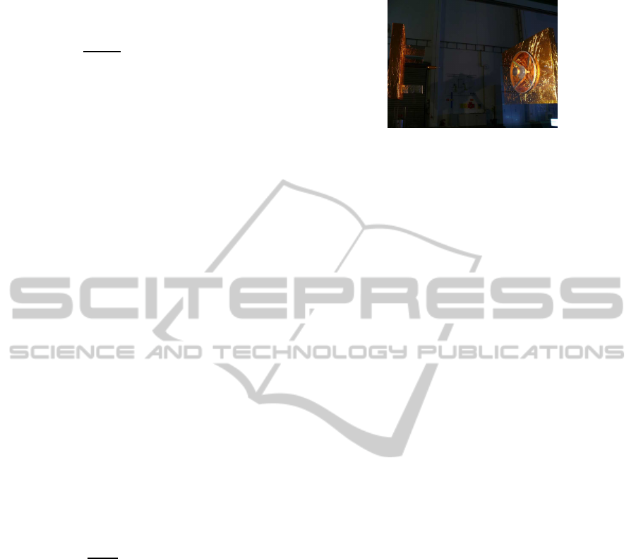
Figure 1: On-Orbit Servcing. Artistic impression of the
German on-orbit servicing mission (DEOS); the robot arm
mounted on a servicer satellite (right) is grasping the client
satellite (left).
c
SpaceTech GmbH
ever, visual algorithms developed for non-lambertian
surfaces are mostly limited to laboratory and far less
applied to real world problems such as visual tracking
of a satellite under direct sunlight.
In this paper we present a visual tracking method
that exploits edges and keypoints for localization of
a satellite for on-orbit servicing. While state of the
art model-based tracking methods are experimentally
well verified for Lamabertian surfaces under ordinary
illumination, we are particularly interested to address
a problem associated to specular object that goes be-
yond the theory of specular reflection. To that end,
our contributions are mainly; (1) we combine edge
and keypoint tracking methods applied to highly spec-
ular object under direct sunlight illumination, (2) we
generate ground truth trajectory under realistic sim-
ulation of satellite and illumination with high power
spotlight to simulate the Sun’s spectrum, (3) we im-
plement the proposed algorithm and evaluate its per-
458
Oumer N..
Monocular 3D Pose Tracking of a Specular Object.
DOI: 10.5220/0004667304580465
In Proceedings of the 9th International Conference on Computer Vision Theory and Applications (VISAPP-2014), pages 458-465
ISBN: 978-989-758-009-3
Copyright
c
2014 SCITEPRESS (Science and Technology Publications, Lda.)

formance (accuracy and robustness) under various
motions and different levels of illumination, and (4)
we compare our hybrid tracking method with edge
based tracking, implemented by adapting Lie algebra
tracking method (Drummond and Cipolla, 1999).
In the remaining sections of this paper, we present
related current state of the art approach of combined
edge and feature based tracking, and review computer
vision methods for specular objects in Section 2. Sec-
tion 3 presents our tracking method that integrates
keypoints and edges in 2D-3D registration. Section
4 describes experimental setup used to validate the
proposed method, and compares tracking results with
edge based methods. Finally we summarize and con-
clude the paper in Section 5.
2 PREVIOUS WORK
In this section, we review pose estimation and struc-
ture reconstruction methods that exploit specular cues
of the object, and briefly explore model-based track-
ing methods which utilize edge and point features of
an object.
2.1 Pose Estimation from Specular Cues
In the context of pose estimation and surface recon-
struction, there exist several contributions that deal
with specular objects. The Theory of a specular ge-
ometry describes that image features exist as either
real or virtual (Oren and Nayar, 1995). Real fea-
tures are directly used by vision algorithms such as
matching, tracking and structure from motion. Vir-
tual features (specular cues) are specular reflections
of a scene or an object features under change of view-
point. Specular surfaces such as a glass and a smooth
metal create ambiguity (actual scene point or reflec-
tion of another scene point) for visual interpretation.
Various methods have been proposed to utilize
these virtual features. For example, shape and re-
flectance parameters can be simultaneously estimated
from multiple views of an object made of single ma-
terial with known lighting (Yu et al., 2004). Phong
reflectance model is used to compute reflectance of
the object shape modelled with triangular mesh, and
minimize non-linear least square cost function over
the shape and reflectance parameters. When the ob-
ject is in motion, specular reflections produce 2D im-
age motion (specular flow) (Oren and Nayar, 1995).
The specular flow is mathematically related to the
3D structure of textured object or scene (Roth and
Black, 2006) and provided a parametric mixture mod-
els for recovery of a surface. Most methods of shape
from specular reflection assume limited case of sur-
faces, in which its structure is known or qualitatively
sparse, and the environment is calibrated. In contrast
(Vasilyev et al., 2008) presented reconstruction ap-
proach that targets general surfaces under unknown
real-world environments. They recovered 3D shape
from optical flow induced by relative motion between
a specular object, an observer and their environment.
Similarly, (Adato et al., 2010) presented variational
optical flow technique, which accounts for character-
stics of specularity including parabolic singularities
related to surface curvature which are hard to detect.
On the other hand, an object tracking with specu-
lar highlights (Gouiff`es et al., 2006) exploits Phong’s
model by approximatinggeneral photometric changes
with a continuous and differentiable function, approx-
imated with first order Taylor series at a pixel point in
the neighbourhood. This approach extends sparse op-
tical flow tracking method such as (Shi and Tomasi,
1994), by compensating for illumination changes and
specular highlights. In the context of pose estima-
tion, unlike classical methods which discard lighting-
information, (Lagger et al., 2008) refined coarse pose
estimates by incorporating lighting information in
texture and specular cues to improveaccuracy of stan-
dard template matching algorithm. In this approach
environment map is retrieved from the specular pixels
of shiny objects and registration is performed in both
image and lighting environment space.
A practical localization and pose estimation
method is demonstrated by (Chang et al., 2009).
They exploited environment map, specular reflections
and specular flow, handling partial occlusions, back-
ground clutter and inter-reflections. Their method re-
quires to use a calibration object such as a mirror
sphere in the target scene to capture the environment
map. It is, however unsuitable for human inaccessible
environments such as satellite orbits.
Despite existence of several physical and geomet-
ric reflectance models of specular objects, they are
rarely exploited for real world problems, mainly be-
cause of their complexity and underlying assumptions
such as placement of a calibration object in the scene.
For a space object such as a satellite, the appropri-
ate reflectance model consists of specular lobe, spec-
ular spike and diffuse reflections. In the presence
of geometric model of the satellite however, specular
highlights, keypoints and edges of the satellite struc-
ture can be better utilized by integrating into standard
model based tracking.
2.2 Feature-based Tracking
Edges of an image are the most suitable cues for 3D
Monocular3DPoseTrackingofaSpecularObject
459

tracking of a space object such as satellite under di-
rect illumination and specularity. They are relatively
robust to illumination change and specularity. More-
over, an accurate and a robust 3D model based track-
ing can be achieved by integrating keypoints and
edges, also reported by (Pressigout and Marchand,
2007), (Vacchetti et al., 2004), and (Kyrki and Kragic,
2005). On one hand, interest points are well local-
ized in textured objects and robust to some lighting
changes and geometric distortions. However, they are
rarely available, unstable on poorly textured objects
and invariant to scale changes. On the other hand,
edges are more distinctive and informative for ob-
jects with sharp edges and strong contrast changes but
ambiguous in cluttered and textured objects because
of strong texture and background clutter. Moreover,
some edges project close to one another and create
ambiguity. Therefore, the combination of edges and
feature points are complementary, enabling more sta-
ble tracking with less-drift than purely edge or point
feature based methods.
Very good results of combined edge and tex-
ture tracking method, which is robust to occlusion,
shadow, and some specularities, are demonstrated in
(Pressigout and Marchand, 2007). Our method con-
siders the dominant specular nature of the object un-
like (Pressigout and Marchand, 2007), which focuses
mainly on lambertian textured surfaces containing
edges. The satellite surface is mainly textureless, with
some irregularities created by thermal insulation ma-
terial and corners created by intersection of segments
(Fig.2).
Figure 2: Specularities because of the satellite surface and
direct illumination. Our region of interest for tracking is
the nozzle (small circle at the center in frontal view) of the
satellite. The nozzle has usually a cone or paraboloid sur-
face geometry and is feature of most satellites.
3 3D TRACKING
The objective of 3D tracking of an object is to localize
its position and orientation in time. In general, there
exist two basic approaches of 3D tracking; model-
based tracking which utilizes the CAD model of the
object, and model free tracking which does not rely
on a geometric model of the object. If the model of
the object is available, it provides useful prior infor-
mation about the object and helps improve robustness
by reducing influence of outliers on the tracker.
In this paper, we localize a space object such
as satellite using model-based approach. A simple
model of the object is used for absolute pose tracking,
using full perspective projection camera model. The
perspective projection of a 3D point p = [X,Y, Z, 1]
T
on image plane under pinhole camera model, is given
by
x = K[R|t]p (1)
where, x is an image point in homogeneous coordi-
nate, K is a camera matrix, and R and t are rotation
and translation of the object in camera frame respec-
tively. Alignment of model and image edges of non-
textured object is efficiently used to recover the ro-
tation and translation of the object, while keypoints
are used for estimating this motion parameters of tex-
tured object. In this section, we present the edge
based and keypoint tracking methods, and formulate
the proposed hybrid feature tracking.
3.1 Edge based 3D Tracking
Edges of an object are widely used feature in model-
based tracking. They are mainly depth discontinu-
ities, including object contours, segments, and primi-
tive shapes such as circles and cylinders. For a close
range (10m to 0.5m) rendezvous of a satellite, its noz-
zle is the most appropriate feature to track, as most
satellites contain this feature to provide thrust for or-
bital control of the satellite. Moreover, the nozzle
is frontal in this close range since the servicer and
the client satellites are well aligned during mid-range
(above 10m) tracking. Consequently the circular ring
of the nozzle is visible in all tracking frames. Hence,
our edge tracking is based on the contours of the noz-
zle in frontal view.
The contours (hereafter all edges are referred to
as contours) are sampled and projected on to the im-
age using hypothetical or predicted pose according to
Eq. (1). Projected model points are associated to each
candidate edge pixel along the respective normals,
also checking against the matching edge directions
(as measured by a Sobel filter), up to a reasonable
threshold. The state of the art model based tracking
methods (Drummond and Cipola, 2002) and (Com-
port and Marchand, 2004) sample contour points dif-
ferently. The former samples 3D contour points and
project each point to image plane while the latter sam-
ples the contours after projecting on the image plane.
VISAPP2014-InternationalConferenceonComputerVisionTheoryandApplications
460

The reader may refer to (Comport et al., 2005) for
comparative study of the two methods.
3.2 Keypoint Tracking
Textured objects consist in distinctive feature points
suitable for tracking. On the contrary textures are
background clutters for purely edge based tracking.
Despite a few in number and sparsely distributed, fea-
ture points of satellite surface are useful for tracking.
Moreover, such keypoints provide additional cues to
estimate correctly the 6D parameter of the motion, as
6 degree of freedom (DOF) motion can not be recov-
ered from certain geometric primitives (e.g circle and
cylinder provide only 5D parameters of 6 DOF mo-
tion of the satellite). Furthermore, when the edges are
weak relative to background clutters, the edge based
tracking gives rise to large errors. Hence, keypoints
are vital to ameliorate robustness and accuracy of vi-
sual tracking.
As 3D keypoints of the satellite are not provided
in our model, we create such model points by back-
projection of detected feature points in the image, at
a known pose estimated using contour based method.
The alternative approach to this method is given by
(Comport et al., 2005), by which they estimate ho-
mography using the pose from edge-based tracker.
Our method is general, in that most satellite surfaces
can be modelled with their primitive shapes such as
cuboid, cylinder, cone, circle and rectangle.
For back-projection of the keypoints, we remodel
the geometry of the frontal surface of the satellite
(see client satellite mock-up in Fig.3), approximated
with right circular cone and cuboid. Although there
exist small unknown curvature at the center of the
cuboid, the model is good approximation to the struc-
ture of the satellite. Accordingly, we compute the 3D
points corresponding to image keypoints through ray
intersection. A ray passing through the image point
x = [u, v]
T
intersects either a cuboid of known size
with normal N or the right circular cone, parametrized
by
(X −V)
T
M(X − V) = 0
A. (X −V) ≥ 0 (2)
M = AA
T
− cos(θ)
2
I
, where A is a direction of the cone axis, θ is an acute
angle of the cone, which is the angle between axis of
the cone and a ray through the point X on the surface
of the cone and the vertex V, and I is identity matrix.
After we create 3D model points, the detected
keypoints are tracked using KLT tracker (Shi and
Tomasi, 1994). Unreliable features are automatically
rejected and substituted by new features during track-
ing. When the 3D model points are not sufficient as
a result of feature rejection, we create model points
from the newly detected features.
3.3 Hybrid Feature Tracking
As stated earlier in this paper, integrating edge and
point features (Fig.4) into 3D tracking corrects draw-
backs of a solely edge-based or feature point track-
ing. In this section, we present the registration of edge
and feature point cues within the same minimization
process, by utilizing 3D point models created by ray
tracing and 3D contour points of a satellite. The 3D
tracking approach is differently handled for the fea-
tures obtained from keypoints and edges; matching
points of the projected contour points are searched
along the edge normals (1D search) while matching
feature points is 2D search. Thus we treat joint opti-
mization of the cost function associated to these fea-
tures in different direction.
Let δp be inter-frame motion. The rigid body
tracking is tantamount to computing the transforma-
tion matrix T in time t for the motion model, provided
the last transformation at time t − 1, according to
T
t
= T
t−1
δT(δp
t
) (3)
where the incremental transform δT is singularity-
free around δT(δp = 0). The tangent space to SE(3)
at T
t−1
is given by the Lie algebra se(3), which pro-
vides δT through the exponential mapping
δT(δp) = exp
6
∑
i=1
G
i
δp
i
!
(4)
where G
i
are the canonical (4× 4) generators of se(3)
(Drummond and Cipolla, 1999).
Each 3D point X, obtained by ray tracing and sam-
pling on the contour, is projected onto image point y
by the respective (3× 4) camera matrix K
y = π(K · T · δT(δp) · X) (5)
where the operator π() transforms from homogeneous
to Euclidean 2D coordinates
π(z) =
z
1
z
3
z
2
z
3
T
. (6)
We minimize the joint objective function
argmin
δT
∑
i
ρ
x
edge
i
− y
i
(δT)
2
+
x
point
i
− y
i
(δT)
2
(7)
where ρ() is a robust function, x
edge
i
and x
point
i
are
edge and tracked feature points respectively.
Differentiating Eq.(5) with respect to incremental
pose parameters δp
i
as
∂y
∂(δp
i
)
δp=0
=
∂π
∂z
z=KTX
· K · J
i
, (8)
Monocular3DPoseTrackingofaSpecularObject
461
gives rise to screen Jacobian, where J
i
is the transfor-
mation Jacobian, given by the respective generator
J
i
= T
∂
∂(δp
i
)
δT(δp)
δp=0
= TG
i
. (9)
The screen Jacobian of each contour point in the
direction of screen normal n is stacked, to form the
Jacobian J
edge
, of maximum size (n
p
× 6). Similarly,
the Jacobian J
point
associated to re-projection error of
3D point models (from ray tracing) is computed, in
this case without screen normal as these model points
are not contour points. Hence, overall Jacobian ( of
size 3n
p
× 6) of the minimization is derived by cas-
cading
J =
J
edge
J
point
T
. (10)
Thus, pose parameters δp are updated by minimiz-
ing residuals r, given by
r =
y
T
i
n
i
u
i
− x
2i
v
i
− y
2i
(11)
where x = [u
i
, v
i
]
T
are tracked image feature points,
x
2i
and y
2i
are projections of 3D points onto the image
plane expressed in standard coordinate.
Several background clutters exist because of spec-
ular reflections, resulting very similar edges to the
nozzle edge. Hence, the tracker should be robust to
outliers. The robust function ρ() in Eq.(7) provides
such functionality to reject spurious features during
tracking. For real time efficiency we choose the M-
estimator adopted in the context of 2D visual servoing
(Comport et al., 2006). The M-estimator adaptively
thresholds outliers based on robust statistics, while
re-weighting inliers according to the Tukey bi-weight
function
w
i
=
b
2
−
r
i
− ¯r
σ
2
!
2
if |r
i
− ¯r| < bδ
(12)
and otherwise the weight is set to zero, where b =
4.6851 is the threshold for Tukey’s function, and the
scale δ is the standard deviation of inlier data, ro-
bustly estimated using the median of absolute devia-
tions (MAD) from the median residual ¯r, and used to
compute the weights. Re-weighted least square min-
imization is performed, by Gauss-Newton update ac-
cording to the Eq.(13)
δp =
J
T
WJ
−1
J
T
Wr (13)
where W is a diagonal matrix containing all weights,
and iterated with the new T matrix, computed by Eq.
(3), until the increment is sufficiently small.
This general formulation can be applied also to
cases with reduced degrees of freedom, by suppress-
ing the Jacobian column related to some of the gener-
ators G
i
. Moreover, for our scenario rotation is con-
trolled quite precisely through attitude measurements
Figure 3: DLR on-orbit servicing simulation system con-
sists of two robots and a satellite mock-up (client). The
servicer (left) and the client with its nozzle(right).
used for control of the satellite, thus we only show re-
sults concerning pure translation and oscillations, by
fixing the rotational part R and using the other three
generators.
4 EXPERIMENTAL RESULTS
In this section, we present the experimental setup and
some of our results at various illumination level and
motion trajectories. As our objective is to address real
world problem of visual tracking, the experiment is
performed with one of the most realistic space simu-
lation system. This system (Fig.3) consists of a high
power floodlight (the Sun simulator), client satellite
covered with thermal protection (such as multilayer
insulation, MLI) which is highly reflective, two 6
DOF Kuka robot system to reproduce relative motion
of servicer and client satellites. The reflective surface
of the client, illuminated with direct Sun light pro-
duces strong specular reflections (see Fig.2), located
on irregular corners and edges. Although these image
features are short-lived and have unstable shape and
size, we are able to achieve reasonable accuracy and
robustness.
We performed the experimentation with various
motions to validate the method and demonstrate the
practicality. The ground truth data is generated
through robot measurements and hand-eye camera
calibration (DLR CalLab toolbox). The maximum
translational and angular velocities are 5cm/s and
1deg/s respectively. The motion is mainly oscilla-
tory with small rotation. The two satellites are as-
sumed controllable, hence relative attitude measure-
ments can be provided with external system. Conse-
quently we focus on oscillatory motion of the client
in this experiment. However, the implemented algo-
rithm can provide poses for 6 DOF motion. We ini-
tialized the tracker manually, which can be also pro-
vided by an external tracker used for mid-range (≥
10m) localization. The implementation is in C++,
while opencv is used for low-level processing such
VISAPP2014-InternationalConferenceonComputerVisionTheoryandApplications
462
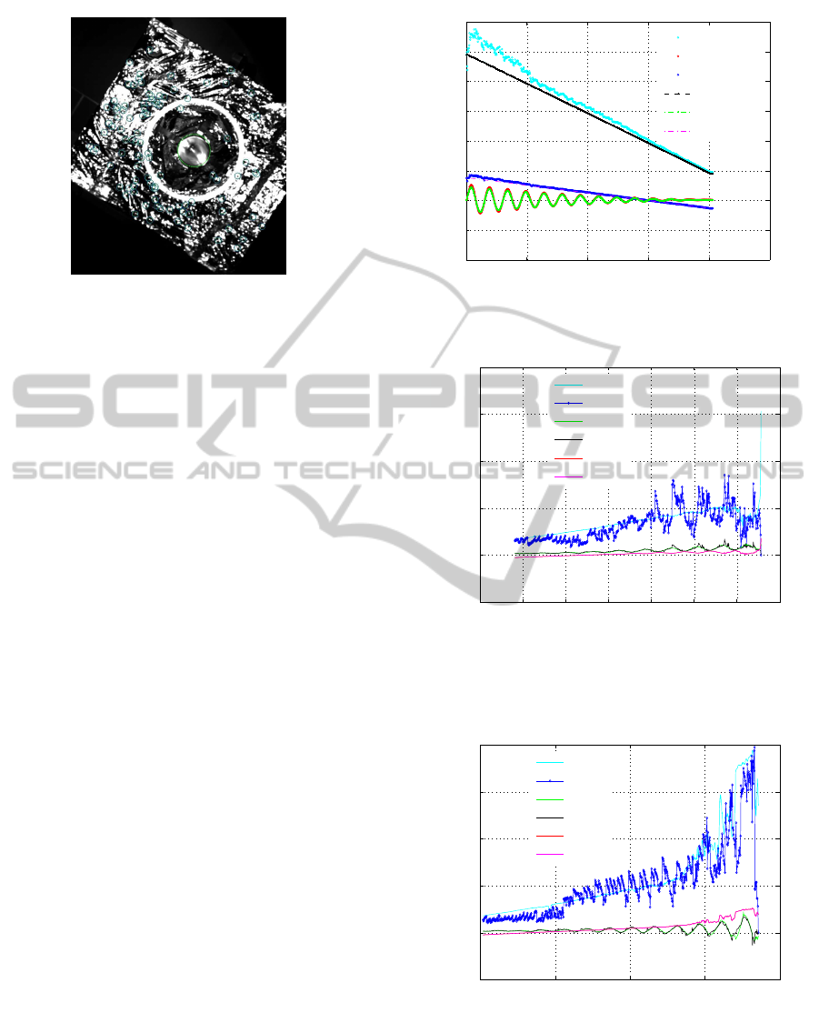
Figure 4: Combined edge and feature point tracking for 3D
localization. Keypoints (small green circles) of irregular
surface and circle of the nozzle (green contour) are tracked.
as edge detection and point feature tracking. The av-
erage processing time for image size of 1024x1024 is
135ms on 2.8GHz processeor.
Hereafter we present experimental results of four
trajectories among our several trajectories (with vari-
ous motion, illumination level and the Sun direction),
and compare combined edge and feature point track-
ing with edge based tracking. Fig.5 illustrates one
of the ground truth and the estimated trajectories. In
the first test trajectory, the client moves from 5m to
1m in Z-direction and from 1m to 0 in X-direction
linearly. It rotates around X-axis with sinusoidal os-
cillation and around Z-axis with linear rotation. The
ground truth error associated to hybrid and edge based
tracking is shown in Fig.6; the dominant motion (of
all trajectories) is along camera Z-axis, hence we dis-
cuss errors in this direction and compare translation
errors by combined edge and feature point tracking,
and edge based tracking method. The error of com-
bined edge and keypoint tracking is relatively smaller,
when the client is close to the camera and far away (at
the beginning). However, the edge based tracking out-
performs combined edge and feature point tracking
around the middle of the trajectory (3m to 2m range).
We explain why such error variation occurred, shortly
after we demonstrate results of other trajectories.
Also we observe similar error distribution in Fig.7,
of which the translation motion of the client is simi-
lar to above except the rotation, which is only around
X-axis alternating with sinusoidal motion. In con-
trast, when the client motion is purely translational
without oscillation, the error of hybrid tracking is rel-
atively smaller at the beginning and larger around the
middle of the trajectory, similar to the rest of the ex-
periment. At very closer range however the error of
the hybrid tracking is approximately comparable to
edge based tracking ( Fig.9) unlike that of other ex-
periments. We would like to remark that all the above
0 200 400 600 800 1000
−2
−1
0
1
2
3
4
5
6
frame
translation [m]
Z−estimated
Y−estimated
X−estimated
Z−true
Y−true
X−true
Figure 5: One of the ground truth trajectories used for vali-
dation and corresponding estimated trajectory of the client.
0.5 1 1.5 2 2.5 3 3.5 4
−0.2
0
0.2
0.4
0.6
0.8
position [m]
absolute translation error [m]
Z− edge
Z− joint
Y− edge
Y−joint
X− edge
X− joint
Figure 6: Comparsion of ground truth errors of hybrid (joint
keypoint and edge) and edge based tracking. The motion is
linear translation along Z- and X-axis while osscillating si-
nusoidally in X-axis and small linear rotation about Z-axis.
1 2 3 4 5
−0.2
0
0.2
0.4
0.6
0.8
position [m]
absolute translation error [m]
Z− edge
Z− joint
Y− edge
Y−joint
X− edge
X− joint
Figure 7: Ground truth errors of hybrid and edge based
tracking. The motion is similar to that of Fig.6 excpet the
client rotates only around X-axis alternating sinusoidally.
experiments are performed while the direction of the
Sun simulator is perpendicular to the camera axis. On
the other hand, the ground truth error of a motion tra-
Monocular3DPoseTrackingofaSpecularObject
463
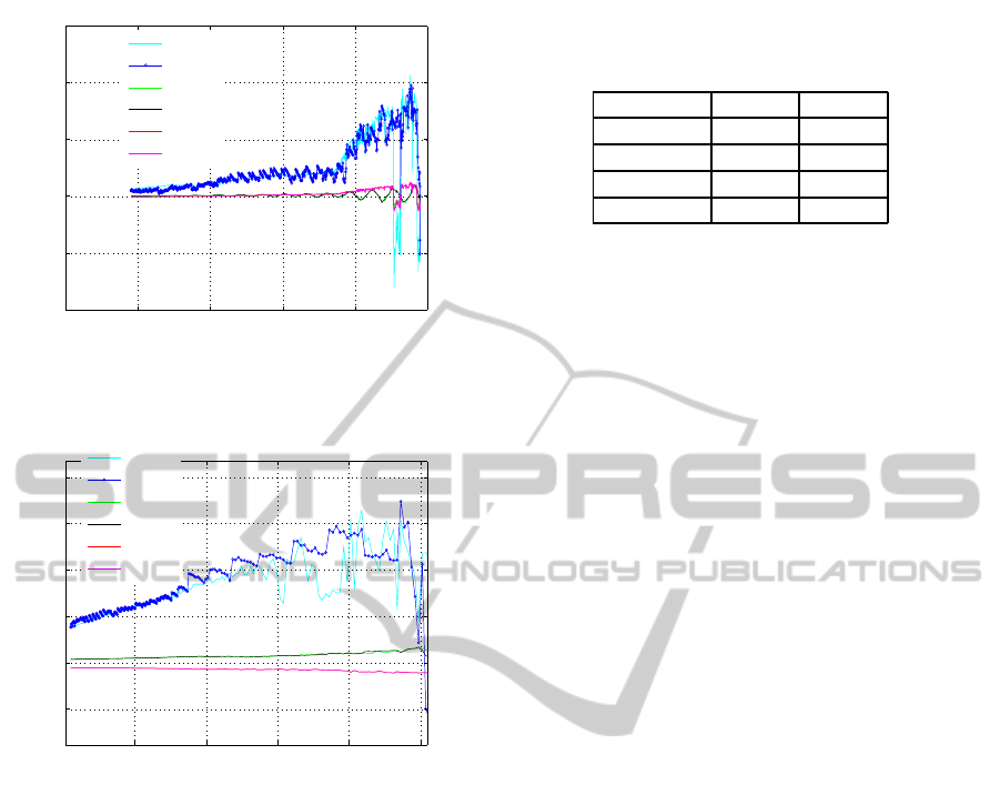
0 1 2 3 4 5
−1
−0.5
0
0.5
1
1.5
position [m]
absolute translation error [m]
Z− edge
Z− joint
Y− edge
Y−joint
X− edge
X− joint
Figure 8: Comparsion of ground truth errors of trajectory
similar to that of Fig.7 but with higher illumination and dif-
ferent direction (60 deg) of the Sun simulator.
2 3 4 5 6
−0.1
0
0.1
0.2
0.3
0.4
position [m]
absolute translation error [m]
Z− edge
Z− joint
Y− edge
Y−joint
X− edge
X− joint
Figure 9: Ground truth errors of purely translational mo-
tion. Edge based tracker provides aprroximately the same
errors as that of hybrid tracking while the former outper-
forms the latter around the middle of trajectory for a such
simple motion.
jectory similar to Fig.7, but the direction of the Sun
simulator about 60 deg to camera axis and illumina-
tion level 10 % higher, is shown in Fig.8. In spite of
the change of the illumination and direction of source
of light, the error of hybrid tracking is comparatively
smaller than that of edge based tracking around simi-
lar regions within the close-range described above.
Combined edge and keypoint tracking outper-
forms edge based tracking in ambiguous region of
the tracking, where the contrast of the nozzle is very
low. The edges extracted from the nozzle of the satel-
lite around 4m are very similar to background edges,
and difficult to track with edge based tracker. In con-
trast, there exist distinctive point features because of
irregular surface of the MLI, which provide important
cues for tracking. Thus, the tracking benefits from
combined keypoint and edges. On the other hand, at
closer range (around 2m) the edge of the nozzle of the
satellite, is sharp with good contrast and can be eas-
Table 1: RMS errors of the edge based and hybrid feature
tracking for various trajectories. The error is in m. The hy-
brid feature tracking outperforms the edge based tracking.
Trajectory Edge Hybrid
1 0.1485 0.1432
2 0.2978 0.2606
3 0.1445 0.1470
4 0.3471 0.3297
ily tracked, however, is not fully visible in the cam-
era field of view. The sharp contours of the nozzle
and distinctive feature points at very close range pro-
vide strong cues for accurate and robust tracking. On
the contrary, the accuracy of the combined edges and
point tracking in the range around 4m to 2m drops
compared to edge based tracking. This is simply be-
cause, feature points are not well localized and drift
quickly. The drift also causes the optimization to con-
verge to local minima, degrading the performance of
the overall hybrid tracking. Thanks to model based
absolute pose tracking, the drift does not accumulate
and recovers to the correct pose when good features
and edges are detected in the subsequent frames. In
general, the accuracy of the hybrid tracking is better
than the solely edge-based tracking, as demonstrated
with root mean square errors of each test trajectory in
Table 1.
5 CONCLUSIONS
We implemented a hybrid tracking method that ex-
ploits image edges and feature points, and demon-
strated experimental results under challenging illumi-
nation condition (directional Sunlight) and visually
difficult reflective surface (satellite). Simple geomet-
ric features such as depth discontinuities and prim-
itive shapes on the satellite provide strong cues for
real time tracking, and are efficient to compute on
standard processor. Although such features of Lam-
bertian object are salient under normal lighting, they
are often ambiguous against background clutters for
specular objects under direct illumination. The am-
biguity is resolved by combining contours and point
features to ameliorate robustness and accuracy. Our
extensive experimentation using camera images, the
Sun simulator, satellite mock-up and simulated mo-
tion (with robots) shows relatively robust and accu-
rate result compared to a standard edge based track-
ing. The tracking result can be used for approach of a
client satellite for on-orbit servicing such as refuelling
and repairing.
Despite the reported improvements, in a few cases
drift of point features can prohibit the utmost ben-
VISAPP2014-InternationalConferenceonComputerVisionTheoryandApplications
464

efit of the hybrid tracking. However, drift free (at
least, reduced drift) feature-based tracking, can be in-
tegrated into edge based tracking. Moreover, our ex-
periment is based on translational motion with small
rotation and oscillation. Large rotation causes large
change of view and the feature points even drift more.
In the future work we will address this large drift
of point features, rotational motion due to tumbling
satellite and illumination changes.
ACKNOWLEDGEMENTS
The author would like to acknowledge Dr. Giorgio
Panin and Dr. Toralf Boge for their invaluable sup-
port.
REFERENCES
Oren Michael and Nayar Shree K. (1995). A Theory of
Specular Surface Geometry. In IJCV’95, International
Journal of Computer vision, volume 24, page. 740–
747.
Lagger Pascal, Salzmann Mathieu, Lepetit Vincet and Fua
pascal (2008). 3D Pose Refinement from Reflections.
In CVPR’08, IEEE Conference on Computer vision
ans Pattern Recognition, pages 1-8, Anchorage, AK.
Yu Tianli, Xu Ning and Ahuja Narendra, (2004). Recover-
ing Shape and Reflectance Model of Non-lambertian
Objects from Multiple Views. In CVPR’04, Proceed-
ings of IEEE Computer Sosciety Conference on Com-
puter vision ans Pattern Recognition, volume 2, pages
II-226 - II-233.
Roth Stefan and Black Michael J., (2006). Specular Flow
and the Recovery of Surface Structure. In CVPR’06,
Proceedings of IEEE Computer Sosciety Conference
on Computer vision and Pattern Recognition, volume
2.
Vasilyev Yuriy, Adato Yair, Zickler Todd and Ben-Shahar
Ohad, (2008). Dense Specular Shape from Multiple
Specular Flows. In CVPR’08, Proceedings of IEEE
Computer Sosciety Conference on Computer vision
ans Pattern Recognition.
Adato Yair, zickeler Todd and Benn-Shahr Ohad, (2010)
Toward robust Estimation of Specular Flow. In
BMVC’10, Proceedings of the British Machine Vision
Conference, pages 22.1–22.11.
Gouiff`es Mich`ele, Collewet Christophe, Fernandez-
Maloigne Christine, Tr´emeau Alain, (2006) Feature
Points Tracking: Robustness to Specular Highlights
and Lighting Changes. In ECCV’06, 9th European
Conference on Computer Vision, volume 4. pages
82-93.
Shi Jianbo and Tomasi Carlo, (1994) Good Features to
Track. In CVPR’94, IEEE Computer Soc. Conference
Computer Vision and Pattern Recognition, pages 593-
600.
Chang Ju Yong, Raskar Ramesh and Agrawal Amit K.,
(2009) 3D Pose Estimation and Segmentation us-
ing Specular Cues. In CVPR’09, IEEE Computer
Soc. Conference Computer Vision and Pattern Recog-
nition, pages 1706-1713.
Vacchetti Luca, Lepetit Vincent, Fua Pascal, (2004) Com-
bining Edge and Texture Information for Real-Time
Accurate 3D Camera Tracking. In ISMAR ’04, Pro-
ceedings of the 3rd IEEE/ACM International Sympo-
sium on Mixed and Augmented Reality Pages 48-57.
Kyrki Ville, Kragic Danica (2005) Integration of model-
based and model-free cues for visual object tracking.
In ICRA05, Proc. of the IEEE Int. Conf on Robotics
and Automation, pages 1554–1560.
Pressigout Muriel and Marchand Eric, (2007) Real-time
Hybrid Tracking using Edge and Texture Informa-
tion. In Proc. of International Journal of Robotics
Research, volume 26, no.7, pages 689-713.
Drummond Tom and Cipolla Robert, (2002) Real-time vi-
sual tracking of complex structures. In PAMI’02 Proc.
of IEEE Transactions on Pattern Analysis and Ma-
chine Intelligence, Volume 27, issue 7, pages 932 -
946 .
Comport A.I. and Marchand Eric, (2004) Robust model-
based tracking for robot vision. In IROS’04 Proc.
IEEE/RSJ International Conference on Intelligent
Robots and Systems, volume 1, pages 692 - 697.
Comport Andrew.I., Kragic Danica, Marchand Eric and
Chaumette Francois, (2005) Robust Real-Time Vi-
sual Tracking: Comparison, Theoretical Analysis and
Performance Evaluation. In ICRA’05 Proc. IEEE In-
ternational Conference on Robotics and Automation,
pages 2841 - 2846.
Comport Andrew I., Marchand Eric and Chaumette Fran-
cois, (2006) Statistically Robust 2D Visual Servoing.
In IEEE Transactions on Robotics volume 22, no.2,
pages 415-421.
Drummond Tom and Cipolla Robert, (1999) Visual Track-
ing and Control using Lie Algebras. In CVPR’99,
IEEE Computer Society, Computer Vision and Pattern
Recognition, volume 2, pages 2652-2659.
Monocular3DPoseTrackingofaSpecularObject
465
