
Enhanced 3D Face Processing using an Active Vision System
Morten Lidegaard
1
, Rasmus F. Larsen
1
, Dirk Kraft
1
, Jeppe B. Jessen
1
, Richard Beck
1
,
Thiusius R. Savarimuthu
1
, Claus Gramkow
2
, Ole K. Neckelmann
2
, Jonas Haustad
2
and Norbert Kr
¨
uger
1
1
Maersk Mc-Kinney Moller Institute, University of Southern Denmark, Odense, Denmark
2
TriVision, Odense, Denmark
Keywords:
Active Vision.
Abstract:
We present an active face processing system based on 3D shape information extracted by means of stereo
information. We use two sets of stereo cameras with different field of views (FOV): One with a wide FOV is
used for face tracking, while the other with a narrow FOV is used for face identification. We argue for two
advantages of such a system: First, an extended work range, and second, the possibility to place the narrow
FOV camera in a way such that a much better reconstruction quality can be achieved compared to a static
camera even if the face had been fully visible in the periphery of the narrow FOV camera. We substantiate these
two observations by qualitative results on face reconstruction and quantitative results on face recognition. As a
consequence, such a set-up allows to achieve better and much more flexible system for 3D face reconstruction
e.g. for recognition or emotion estimation based on the characteristics of a given face.
1 INTRODUCTION
In this paper, we make use of active vision for enhanc-
ing the 3D reconstruction of a face to be used, e.g., in
the context of face and emotion recognition (see fig-
ure 1). It is known that vision based face recognition
systems making use of 3D information are very pow-
erful since by means of the 3D shape of a face, highly
invariant and discriminative feature vectors can be ex-
tracted. One important reason for that is – compared
to 2D features – a high robustness against illumination
changes. However, such systems require a reasonable
resolution of the face and by that they are usually lim-
ited to a constrained area in which the face needs to
be visible. A possibility to overcome this problem is
to separate the problem of face finding - which usu-
ally requires a much lower resolution of the face in
the image – and the 3D face processing. We do that
by using a wide field of view (FOV) camera for face
finding and a narrow FOV camera for face recogni-
tion (see Fig. 1a). Both cameras are placed on a pan-
tilt unit (PTU) where – based on the image informa-
tion of the wide FOV camera – the PTU is controlled
This work was funded by the project ’SenseBot (Wel-
fareTech, http://en.welfaretech.dk/)’ and supported by Wel-
fare Tech Region.
in a way that allows the narrow FOV camera to take
pictures of a centred face with higher pixel resolution
(see Fig. 2). Fig. 1b) through d) depicts two possi-
ble application areas where the use of an active vision
system could enhance the 3D face processing results.
Fig 1b) represents a face recognition system and c)
and d) represents face capturing as input for an emo-
tion estimation system e.g. based on the 3D facial
structure.
We want to stress that the focus of this paper is
on the role of active vision in face processing and
not on face recognition. We will show that the use
of active vision has two positive effects: First, as an
obvious fact, it allows for extending the operational
space of the system (see figure 3). Moreover, it also
enhances the 3D reconstruction by providing an im-
proved camera placement relative to the face, i.e., by
bringing the face into the area of optimal reconstruc-
tion uncertainty. The second point is purely based on
a geometric argument and is often overlooked.
One of the more popular approaches for face de-
tection is the Viola and Jones algorithm (Viola and
Jones, 2004) which has been adapted by (Cristi-
nacce and Cootes, 2006; Douxchamps and Campbell,
2008). Either the algorithm is used directly for face
detection or for feature detection of the face. The
466
Lidegaard M., Larsen R., Kraft D., Jessen J., Beck R., Savarimuthu T., Gramkow C., Neckelmann O., Haustad J. and Krüger N..
Enhanced 3D Face Processing using an Active Vision System.
DOI: 10.5220/0004667904660473
In Proceedings of the 9th International Conference on Computer Vision Theory and Applications (VISAPP-2014), pages 466-473
ISBN: 978-989-758-009-3
Copyright
c
2014 SCITEPRESS (Science and Technology Publications, Lda.)

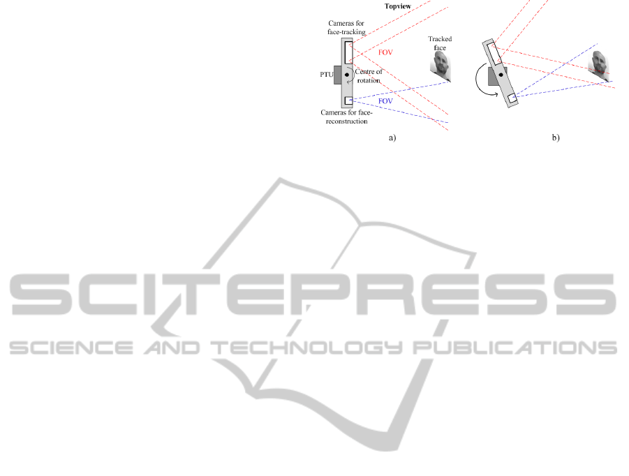
Figure 1: The physical construction of the active vision system showing the position of the mounted cameras (blue) and the
axes of the PTU (red) is depicted in a). Fig. b) show a face recognition system used for access allowance. Figures c) and d)
are showing tracked faces (left images) while watching a video (right image). c) facial expression during a happy video-scene
and d) during a more sad video-scene. Scene from The Lord of the Rings - The Fellowship of the Ring, New Line Cinema,
2001.
Viola and Jones algorithm is also utilised within the
work presented by this paper.
Face recognition is a widely studied area. Tolba
et al. (Tolba et al., 2006) provide a nice review of
the topic. Some early work utilising active vision
for face authentication in a 2D approach is presented
by Tistarelli et al. (Tistarelli and Grosso, 2000) as
a system used for authentication in banking applica-
tions. A pair of active vision cameras captures spe-
cific invariant facial features which are automatically
extracted utilising morphological processes. A simple
matching algorithm based on correlation between log-
polar images of the one requesting access and stored
images is used for the verifying process.
Another of the earlier utilisations of active sys-
tems in a 2D approach is presented by Darrell et
al. (Darrell et al., 1996). A real-time face tracking
system used for face tracking in an unconstrained in-
teractive environment by utilising an active foveated
system for extracting position and pose of the face by
analysing Eigen-space features of the face. The sys-
tem is based on a fixed wide-angle scene camera pro-
viding feedback to a PTU controlled narrow-angled
camera tracking the face.
Of more recent work, (Kri
ˇ
zaj et al., 2012) ad-
dresses the advantages of utilising 3D features for
robust face recognition in uncontrolled environments
using an active 3D sensor, e.g. the Microsoft Kinect
camera. Contrary to our approach, the system is based
on a stationary set-up utilising 3D sensors whereas
we utilise an active vision system combined with high
resolution stereo cameras for the 3D face reconstruc-
tion.
According to our knowledge, there is only one ap-
proach using active vision in the context of face pro-
cessing based on two stereo systems: (Utsumi et al.,
2012) utilises two pan-tilt-zoom (PTZ) camera sets
in combination with a stationary camera for finding
and tracking faces of persons traversing a path under
surveillance. High-level feedback from an inference
engine is used to determine the best captured camera
view of the tracked face for recognition. It is different
to our approach in the sense that they focus on the use
of PTZ cameras for face tracking. We have a single
PTU with two fixed focal length pairs of stereo cam-
eras; one to track the face in 3D and another to per-
form high quality reconstruction as a preparatory step
for 3D shape based face recognition. This high qual-
ity 3D reconstruction allows for reliable face recogni-
tion, whereas (Utsumi et al., 2012) need a set of 2D
images for training as well as matching to get reliable
recognition.
In this paper, we show qualitatively as well as
quantitatively that by utilising an active vision sys-
tem we can 1) improve reconstruction quality, and by
that 2) improve recognition in the limited workspace
spanned by a passive system and 3) extend the
workspace considerably.
Enhanced3DFaceProcessingusinganActiveVisionSystem
467

Figure 2: Sketch of the overall data flow through the system. Images from the wide FOV cameras a+b) provide the information
for rotating c) the high resolution cameras d) into position using the PTU for gaining centred images of the tracked face e) for
the 3D reconstruction f) and finally the recognition evaluation g).
2 SYSTEM OVERVIEW
The overall active vision system consist of two stereo
cameras mounted atop a pan-tilt unit. The stereo cam-
era having a wide FOV is used for face finding and
tracking in combination with the PTU. A geometrical
reconstruction of the point representing the center of
the face with respect to the face-tracking cameras is
used as reference point for rotating the second stereo
camera into an optimal position for capturing high
resolution images of the tracked face. Two separated
computer systems are utilised for the data processing;
one for the face finding and tracking and another for
the 3D face reconstruction and face recognition. The
physical construction of the active vision system in-
cluding the PTU and the mounted cameras is shown
in Fig. 1 a).
On the right side of Fig. 1a), the face track-
ing cameras are located and on the left, the high-
resolution cameras for the 3D reconstruction are
mounted vertically to avoid occlusion of the nose and
make as much of the face mutually visible for the
two high resolution cameras as possible. The physical
construction for mounting the cameras on the PTU is
a 3D printed CAD-model. The PTU has two distinct
axes of rotation indicated as the red dashed lines seen
in Fig. 1 a) and Fig. 2 c).
A schematic model of the overall system is
sketched in Fig. 2 including examples of images from
the two camera sets combined with indication of the
data-flow through the system. Firstly the images from
the wide FOV cameras are utilised for face finding
and tracking. The location of the face in 3D space
is estimated and used as a reference point for rotat-
ing the high resolution cameras into position for cap-
turing high resolution images of the tracked face in
the centre of the image by means of the PTU. The
high resolution stereo images are then used for recon-
structing the face and generate a 3D face-model. Fea-
tures extracted from the generated 3D face model are
compared to existing entries in a database. Finally,
a matching evaluation is initiated for determining a
recognition or not.
In the following subsections, we first address the
approach of the face detection followed by a descrip-
tion of the tracking system. Then, the face recogni-
tion is described and finally the combined system is
presented. For more details about the face tracking
system we refer to (Larsen, 2011).
VISAPP2014-InternationalConferenceonComputerVisionTheoryandApplications
468
2.1 Face Detection
The finding and tracking of a face is based on the
wide FOV stereo camera. The face tracking system
utilises the OpenCV implementation of the Viola and
Jones face detector (Viola and Jones, 2004) which
consists of groups of weak classifiers with high detec-
tions rates and low rejection rates. The weak classifier
has a correct detection-rate just above chance. Several
groups of weak classifiers are then combined forming
a cascade. At any stage, when a rejection is encoun-
tered, the process exits (candidate not in class). Only
when all stages in the cascade of weak classifiers have
responded positively, a face-detection is declared (Vi-
ola and Jones, 2004).
The algorithm is trained for frontal faces and both
left and right profile detections. In combination, the
system is capable of detecting the face of a panning
head. At this point only one face can be tracked at a
time and the system cannot handle head roll or faces
looking up or down.
2.2 The Tracking System
Whenever a face has been detected by the stereo cam-
era with the wide FOV, the centre point of the detected
face is geometrically reconstructed in 3D space. The
reconstructed centre point is then used as a refer-
ence point for rotating and repositioning the PTU and
hence the cameras. The positioning system utilises
a geometrical model of the physical tracking system,
including the two stereo cameras, and the reference
point to define the proper movements to reposition the
high resolution cameras directing them towards the
reconstructed centre point of the tracked face. Hence,
when a face is detected by the wide FOV cameras,
the high resolution cameras is directed towards the
tracked face. The PTU is controlled by constant speed
movement defined by the error E
di f f erence
between the
current orientation P
current
and the desired orientation
P
desired
of the high resolution cameras as indicated in
equation 1. The position of the cameras is updated
with a frequency of approximately 5 Hz. Both the
pan and tilt dimensions are included in the current po-
sition, desired position and error difference.
P
desired
= P
current
+ E
di f f erence
(1)
A geometric interpretation of the tracking is seen
in Fig. 3. Only the pan-dimension is shown but the
principle is the same for the tilt-direction.
Figure 3: Principle of the active vision system during face
tracking. A face is detected by the wide FOV (marked in
red) cameras shown in a) and the PTU rotates and reposition
the high resolution cameras (marked in blue) directing them
towards the centre of the tracked face as shown in b).
2.3 3D Facial Processing
Face recognition by means of matching a given face
to a database of faces, is a non-intrusive biometric
method that dates back several decades. In the last
years, there has been a renewed interest in develop-
ing new methods for automatic face recognition. This
renewed interest has been fuelled by advances in com-
puter vision techniques, computer design, sensor de-
sign, and face recognition systems. 3D face recogni-
tion algorithms identify faces from the 3D shape of
a person’s face. Face recognition systems not based
on 3D information are affected by changes in lighting
(illumination) and pose of the face which reduce per-
formance. Because the shape of faces is not affected
by changes in lighting or pose, 3D face recognition
has the potential to improve performance under these
conditions (Jafri and Arabnia, 2009).
In our system, we perform the following steps:
Firstly a 3D face model must be obtained. Two com-
mon approaches are stereo-imaging and the use of
structured light sensors, e.g. the Microsoft Kinect.
Once the 3D model is obtained, invariant measures
can be extracted. One approach described in the liter-
ature (Mata et al., 2007) computes geodesic distances
between sampled points on the facial surface. Based
on these distances, the points are then flattened into a
low-dimensional Euclidean space, providing a bend-
ing invariant (or isometric invariant) signature surface
that is robust to certain facial expressions. Finally, the
signature is compared with a database of signatures.
The high resolution cameras utilised for the 3D
reconstruction and recognition part are acquiring im-
ages in continuous mode. For each pair of images a
face detector – also the OpenCV implementation of
the Viola and Jones face detector (Viola and Jones,
2004) – is checking if a face is present in the image.
If a face is detected in both images of the stereo cam-
era, the position of the face is compared with the face
Enhanced3DFaceProcessingusinganActiveVisionSystem
469
position in the next image pair. If sufficient stability
is detected between the positions of the face in the
consecutive image pairs, it is assumed that no motion
blur occurs and the current stereo image is transferred
to the 3D modelling system. The system generates
a 3D model from the stereo image by use of stereo
reconstruction.
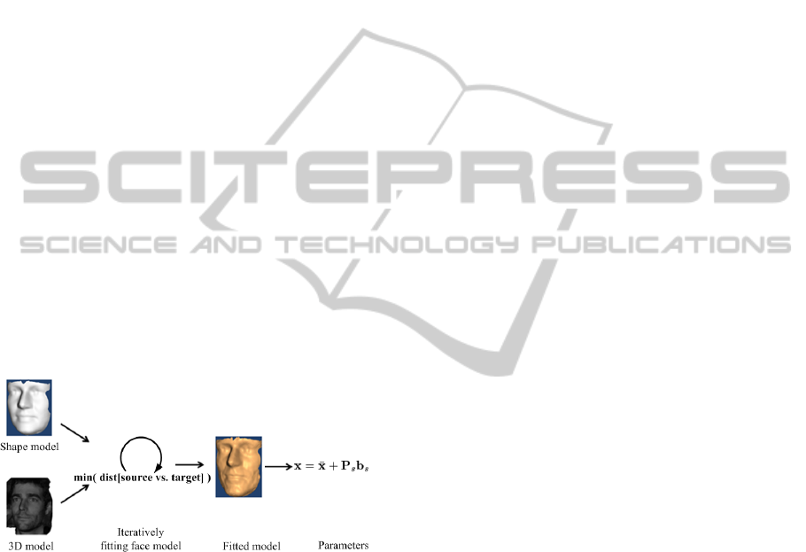
When a 3D model has been generated, a shape
model based on a number of controlling parame-
ters is fitted to the 3D model. This approach is
based on the active appearance model (AAM) intro-
duced by (Cootes et al., 1998). The position, orien-
tation and model weight parameters are fitted to the
reconstructed 3D-model to minimize the 3D resid-
ual between the shape model surface and the 3D-
reconstruction. The fitting process is performed itera-
tively based on the updated shortest distance between
the source and target models. The standard deviations
of the derived shape model are balanced to avoid over-
fitting. The principle of the first part of the system is
sketched in Fig. 4 and Fig. 5 (first four steps until pa-
rameters). In the formula for the shape model, x is
the fitted shape model of a specific person, whereas
on the right hand side
¯
x is the shape model of an av-
erage face. P
s
is the principal components of how the
face model changes according to a training set, and
the weights b
s
represents a key or the ID of the spe-
cific person.
Figure 4: Shape model parameter fitting.
When the fitting procedure has finished, the result-
ing set of parameters (which include the facial scale,
and the contribution of each of the active shape model
modes used to model the face) is sent to the recogni-
tion module. The database contains a set of parame-
ters for each person enrolled in the system. The recog-
nition is based on a comparison between the current
person and each person in the database. The compar-
ison is evaluated as a measurement of the geometrical
distance between one set of parameters and another
set of parameters. If the geometrical distance is be-
low a certain threshold, the person is recognized as
being enrolled previously (see figure 5).
2.4 The Combined System - An Active
Vision System
The dynamic tracking of a face utilising the PTU and
wide FOV stereo cameras provide the necessary ge-
ometrical information in order to bring the face into
the centre of the captured images from the high res-
olution cameras. The two systems, the active face
tracking system and the system for 3D reconstruction
and recognition of the tracked faces, are two indepen-
dent systems realized on two different computers. No
communication is exchanged during operation. The
active tracking system tracks faces within the wide
FOV whenever a face is present. The system for 3D
reconstruction and recognition of faces independently
detects faces within the FOV of the high resolution
cameras. Whenever a face is present and the images
are sufficiently stable, the system captures high reso-
lution images of the face, initiates the reconstruction
and search for a match in the database.
When a face is recognised, different actions can
take place depending on the application such as door
or building access, computer system access, etc.
3 ADVANTAGES OF ACTIVE
VISION
An active vision system provides numerous advan-
tages over a stationary system. One obvious advan-
tage is the increased workspace for e.g. face track-
ing as outlined in section 3.1. Moreover, the active
movement of the cameras bringing the face into the
centre of the captured images and by that the accu-
racy of the reconstruction of the faces is increased –
compared to a positioning of the face in the periphery
of the narrow FOV image – due to the geometric con-
straints discussed in section 3.2. Due to the increased
accuracy in the geometrical reconstruction, a more ac-
curate 3D-face model can be generated, thus a higher
recognition rate should be achieved. The following
subsections will describe these two advantages in de-
tail.
3.1 Extension of the Field of View
By utilising a PTU for the face tracking, the
workspace of the system significantly increases. A
stationary vision system utilising only the two high
resolution cameras has a working space defined by
the overlapping FOV of the high resolution cameras
where the face is sufficiently visible to both cameras.
By adding the PTU to the tracking of the face the sys-
VISAPP2014-InternationalConferenceonComputerVisionTheoryandApplications
470
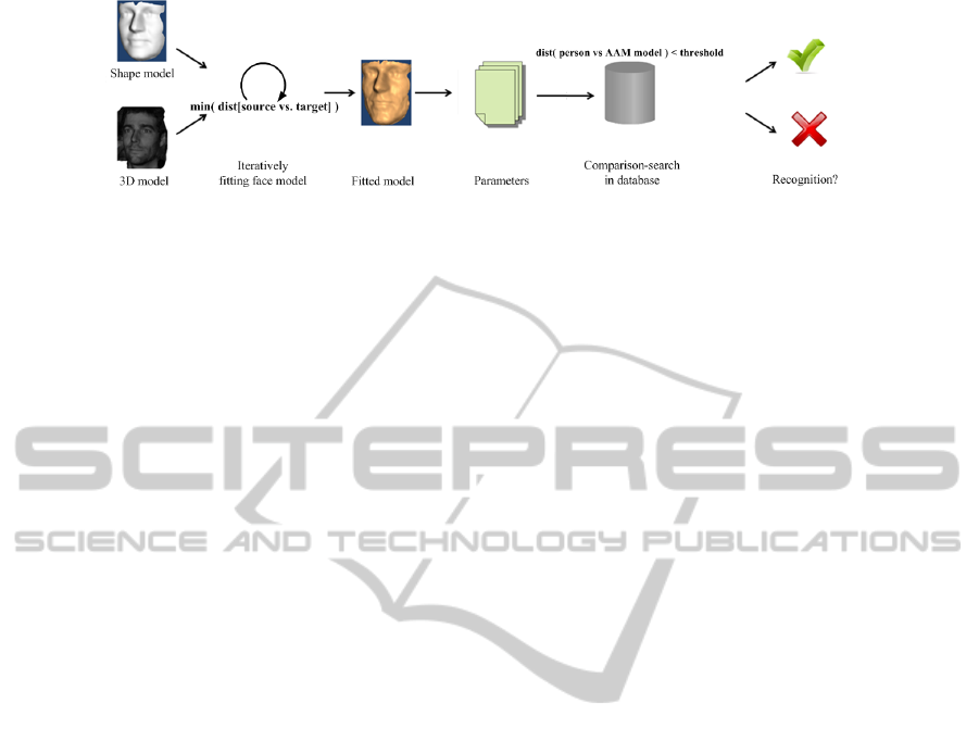
Figure 5: Recognition by finding matching parameters in the database.
tem becomes an active system and the workspace in-
creases only to be limited by the specifications of the
PTU. The distance between the high resolution cam-
eras and the face does not increase when utilising an
active vision system of this type and hence remains
unchanged. The principle of the increased workspace
is seen in Fig. 6 a).
3.2 Reconstruction Quality in the Field
of View
The uncertainty in reconstruction of a 3D point can
be expressed by the trace of the covariance matrices,
i.e., the sum of the Eigen-values (see, e.g. (Pugeault
et al., 2008) or (Hartley and Zisserman, 2003)). In
Fig. 6 b) and c) the trace tr of the reconstructed posi-
tion’s covariance matrix at different locations in space
as indicated by the planes in 6 d) and e). These fig-
ures show that the reconstructed position’s covariance
is affected by the distance from the primitive to the
cameras’ optical centres and ’peripheriness’. As can
be seen in Fig. 6 b), the trace tr(Λ
m
) increases with
z-distance but also when the x-coordinate approaches
the periphery of the visual field. The increase of un-
certainty is even more obvious, when a cut through
the visual field along the x-y plane parallel to the im-
age plane is done as shown in Fig. 6 c).
Transferring the theoretical degradation of un-
certainties of 3D point-recon-struction to the face-
tracking system, the reconstruction quality of the
tracked faces should decrease when the face is moved
away from the image centre. Examples of nine high
resolution image pairs, each with the face located in
different positions in the images, are shown in Fig. 7
a). The 3D reconstructed faces from the high reso-
lution image pairs are seen in b). The principle of
the connection between which position correspond to
which 3D reconstruction is marked in red. This prin-
ciple also applies for Fig. 7 c).
From figures 7 b) and c) it can be observed that the
best reconstruction of the faces is apparent when the
faces are located in the centre of the image. It is also
observed that the degradation of the reconstruction is
worst at the outward pointing side of the face when
the face is located in the periphery of the images. Se-
vere artefacts due to image clipping are observed in
the upper and the lower reconstructions. Moreover,
artefacts are more prominent at the outwards pointing
sides of the faces.
Around the 3D reconstructed faces artefacts from
the background are present. Reconstruction degrada-
tion is also observed in the outer parts of the faces
due to the rounding of the face-edges and beginning
occlusion.
4 RECOGNITION RESULTS
The above mentioned advantages of using an active
vision system compared to a stationary system are
twofold. First in terms of reconstruction quality and
accuracy and second in terms of a larger workspace.
The effect of the reconstruction advantages have been
shown qualitatively in Fig. 7 b) and c) and can also be
investigated by means of a more quantitative measure.
As a consequence of a more accurate reconstruction
of the tracked face by utilising the active vision sys-
tem, compared to a stationary system, a higher recog-
nition rate is present as will be outlined below. Here
we want to stress again that the focus of the paper is
not on face recognition but on demonstrating the ef-
fect of using active vision on face processing. Hence
what is important here is to demonstrate the improve-
ment of face recognition when using active vision
compared to not using active vision for which a data
base of relative moderate size is sufficient.
In a stationary system 10 subjects have been posi-
tioned in three different positions with respect to the
high resolution cameras, hence the faces were located
in roughly three positions in the high resolution im-
ages which are used for the 3D reconstruction. In
comparison to this, the active vision system has been
utilised in a similar manner, only the faces will now be
positioned in the centre of the high resolution images
regardless of the physical position of the face with re-
spect to the high resolution cameras as an effect of
using the active vision system. A graphical interpre-
tation of the set-up and principles are shown in Fig. 8
Enhanced3DFaceProcessingusinganActiveVisionSystem
471
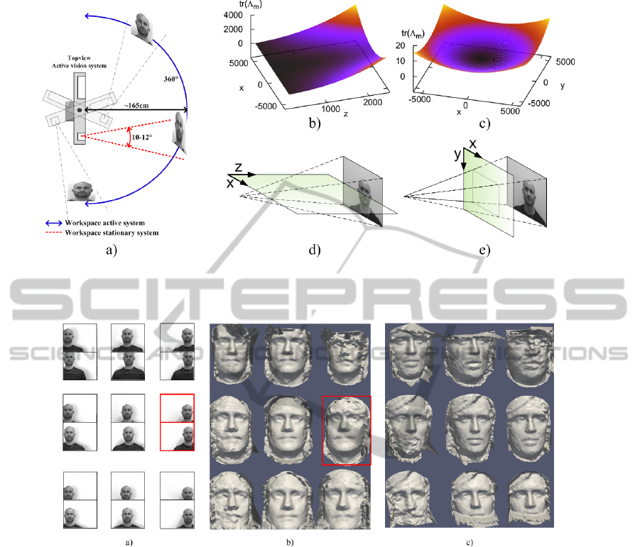
Figure 6: Figure a) show the extended workspace. The dependency of uncertainty in reconstruction concerning periphery
view is depicted in b) and distance in c). Fig. d) and e) indicate the connection between the uncertainty graphs in b) and c)
with respect to FOV of a camera. Figures b) and c) from (Pugeault et al., 2008).
Figure 7: In a) nine different examples of image pairs from the high resolution cameras with nine different locations of the
face within the images is seen. Figure b) and c) show two different examples the reconstruction degradation vs. face-position
represented by the face positions in a). The principle of the connection of the high resolution images pair and the correspondent
3D reconstruction image in b) is marked in red. The principle of the face position and correspondent recognition also apply
for c).
a) and b). Examples of outputs are seen in Fig. 8 c)
and d). No vertical corrections have been made by
the system, only horizontal correction repositioning
the face in the centre of the high resolution images.
The recognition results when utilising an active
vision system compared to using a stationary vision
system are shown in Table 1. The table show correct
recognition rates in each of the three positions with
and without usage of the PTU. From the upper row
of the table it is observed that the recognition rate is
higher, 85% compared to 69.1% and 61.6%, when-
ever the face is positioned in the centre of the high
resolution images. When utilising the active vision
system, the percentages for the left and right posi-
tions increases to levels matching the centre position.
The percentages are 88.0%, 86.0% and 91.0% for the
left, centre and right positions, respectfully. During
the testing no false positives were detected (false pos-
itives: giving access to a non-correct match).
5 CONCLUSIONS AND FUTURE
WORK
An active vision system in the context of face recog-
nition based on 3D information has been examined by
means of qualitative and quantitative measures. There
are two main advantages of such a system compared
to a stationary set-up. First, the workspace can be
VISAPP2014-InternationalConferenceonComputerVisionTheoryandApplications
472

Figure 8: Principle of the test set-up. In figure a) the stationary set-up is seen with the active vision system disabled. In figure
b) set-up with the active vision system enabled is seen. Figures c) and d) show outputs from the stationary system and from
the active system respectively, both with the face positioned on the left with respect to the cameras.
Table 1: Correct face-recognitions based on 10 recogni-
tion attempts on 10 subjects. The subjects was positioned
in three different locations with respect to the common
mid-line of the high-resolution cameras; Left, Center and
Right. No false-positives were detected (No falsely access
allowances).
Left Center Right
No PTU 69.1% 85.7% 61.6%
With PTU 88.0% 86.0% 91.0%
enlarged significantly. Secondly, by means of theo-
retically geometrical constraints of a vision system,
the reconstruction accuracy and hence reconstruc-
tion quality can be increased significantly since the
tracked face stays in the centre of the captured high
resolution images used for the reconstruction. We
showed this dependency through qualitative results
for the 3D reconstruction of faces as well as quanti-
tatively by means of improvement of face recognition
performance. We have given two application exam-
ples of our system, face recognition as well as emo-
tion recording and recognition as seen in figure 1.
REFERENCES
Cootes, T. F., Edwards, G. J., and Taylor, C. J. (1998). Ac-
tive Appearance Models. In Proc. European Confer-
ence on Computer Vision.
Cristinacce, D. and Cootes, T. F. (2006). Facial Feature
Detection and Tracking with Automatic Template Se-
lection. In Proceedings of the 7th International Con-
ference on Automatic Face and Gesture Recognition.
Darrell, T., Moghaddam, B., and Pentland, A. P. (1996).
Active Face Tracking and Pose Estimation in an Inter-
active Room. In Proceedings of the 1996 Conference
on Computer Vision and Pattern Recognition (CVPR
’96).
Douxchamps, D. and Campbell, N. (2008). Robust real-
time face tracking for the analysis of human be-
haviour. In Proceedings of the 4th international con-
ference on Machine learning for multimodal interac-
tion.
Hartley, R. and Zisserman, A. (2003). Multiple View Geom-
etry in Computer Vision. Cambridge University Press.
Jafri, R. and Arabnia, H. R. (2009). A Survey of Face
Recognition Techniques. Journal of Information Pro-
cessing Systems, 5(2).
Kri
ˇ
zaj, J.,
ˇ
Struc, V., and Dobri
ˇ
sek, S. (2012). Robust 3D
Face Recognition. Elektrotehni
ˇ
ski Vestnik, 79:1–2.
Larsen, R. F. (2011). Face finding, tracking and pose esti-
mation with a multi-resolution stereo camera system
mounted on a pan-tilt unit. Master’s thesis, University
of Southern Denmark.
Mata, F. J. S., Berretti, S., Bimbo, A. D., and Pala, P. (2007).
Using geodesic distances for 2D-3D and 3D-3D face
recognition. In 14th International Conference of Im-
age Analysis and Processing.
Pugeault, N., Kalkan, S., W
¨
org
¨
otter, F., Baseski, E., and
Kr
¨
uger, N. (2008). Relations between reconstructed
3d entities. In VISAPP, pages 186–193.
Tistarelli, M. and Grosso, E. (2000). Active vision-based
face authentication. Image and Vision Computing,
18(4):299314.
Tolba, A. S., El-Baz, A. H., and El-Harby, A. A. (2006).
Face Recognition: A Literature Review. International
Journal of Information and Communication Engineer-
ing.
Utsumi, Y., Sommerlade, E., Bellotto, N., and Reid, I.
(2012). Cognitive Active Vision for Human Identifi-
cation. In IEEE International Conference on Robotics
and Automation.
Viola, P. and Jones, M. J. (2004). Robust Real-Time Face
Detection. International Journal of Computer Vision,
57(2):137–154.
Enhanced3DFaceProcessingusinganActiveVisionSystem
473
