
Hand-eye Calibration with a Depth Camera: 2D or 3D?
Svenja Kahn
1
, Dominik Haumann
2
and Volker Willert
2
1
Fraunhofer IGD, Darmstadt, Germany
2
Control Theory and Robotics Lab, TU Darmstadt, Darmstadt, Germany
Keywords:
Hand-eye Calibration, Depth Cameras, Pose Estimation, Image based Calibration, Geometric Alignment, 3D
Measurements, Iterative Closest Point Algorithm, Comparative Evaluation.
Abstract:
Real time 3D imaging applications such as on the fly 3D inspection or 3D reconstruction can be created
by rigidly coupling a depth camera with an articulated measurement arm or a robot. For such applications,
the ”hand-eye transformation” between the depth camera and the measurement arm needs to be known. For
depth cameras, the hand-eye transformation can either be estimated using 2D images or the 3D measurements
captured by the depth camera. This paper investigates the comparison between 2D image based and 3D
measurement based hand-eye-calibration. First, two hand-eye calibration approaches are introduced which
differ in the way the camera pose is estimated (either with 2D or with 3D data). The main problem in view
of the evaluation is, that the ground truth hand-eye transformation is not available and thus a direct evaluation
of the accuracy is not possible. Therefore, we introduce quantitative 2D and 3D error measures that allow
for an implicit evaluation of the accuracy of the calibration without explicitly knowing the real ground truth
transformation. In view of 3D precision, the 3D calibration approach provides more accurate results on average
but requires more manual preparation and much more computation time than the 2D approach.
1 INTRODUCTION
Depth cameras capture dense 3D point clouds in real
time. Tasks such as 3D difference detection, bin-
picking or simultaneous localization and mapping
can be addressed by rigidly coupling a depth camera
with an articulated measurement arm or with a robot
(Fuchs, 2012)(Kahn et al., 2013). To transform the 3D
measurements of the depth camera into the coordinate
system of the articulated arm, the relative transforma-
tion between the depth camera and the measurement
arm needs to be known. This transformation is called
”hand-eye transformation”.
For 2D color cameras, estimating the hand-eye
calibration between the 2D camera and a robot or
a coordinate measuring machine such as a measure-
ment arm is a well researched task (Tsai and Lenz,
1988)(Strobl and Hirzinger, 2006). Recently, the
technological advances of real-time depth imaging
brought up the question how to estimate the hand-
eye transformation for 3D depth cameras. As most
depth cameras also output a 2D intensity image in ad-
dition to the depth measurements, an obvious solution
is to use the same algorithms for depth cameras as
for 2D color cameras. For instance, Reinbacher em-
ployed such an image based approach for the hand-
eye calibration between a depth camera and a robot
(Reinbacher et al., 2012). Kahn described an image
based hand-eye calibration between a depth camera
and an articulated measurement arm (Kahn and Kui-
jper, 2012). In contrast to these 2D image based hand-
eye calibration procedures, Kim used the 3D mea-
surement at the center of a marker for the hand-eye
calibration (Kim and Ha, 2013). Fuchs proposed a
solution which uses depth measurements instead of
2D images (Fuchs, 2012). This approach employs
a calibration plane with known position and orienta-
tion. The hand-eye calibration is estimated by solving
a least squares curve fitting problem of the measured
depth values with the calibration plane.
While both 2D and 3D data based approaches
have been proposed, little is known about the accu-
racy and the suitability of these approaches for the
hand-eye calibration with a depth camera. The ac-
curacy of the hand-eye transformation is either not
evaluated at all (Reinbacher et al., 2012)(Kahn and
Kuijper, 2012) or just for specific calibration proce-
dures (Fuchs, 2012). This complicates the decision
whether to estimate the hand-eye transformation with
a 2D or with a 3D data based approach. It is unknown
whether 2D data based approaches have major advan-
tages compared to 3D data based approaches (or vice
481
Kahn S., Haumann D. and Willert V..
Hand-eye Calibration with a Depth Camera: 2D or 3D?.
DOI: 10.5220/0004668604810489
In Proceedings of the 9th International Conference on Computer Vision Theory and Applications (VISAPP-2014), pages 481-489
ISBN: 978-989-758-009-3
Copyright
c
2014 SCITEPRESS (Science and Technology Publications, Lda.)
versa), or whether both kinds of approaches can pro-
vide comparable results.
This paper contributes to this unsolved research
question with three main contributions. First, we pro-
pose a 3D measurement based hand-eye calibration
using the same transformation estimation principle as
a previously published 2D image based hand-eye cali-
bration procedure (Kahn and Kuijper, 2012). The dif-
ference between both approaches is the way the posi-
tion and orientation of the depth camera is estimated:
either by analyzing the captured 2D image, or by ge-
ometrically aligning the 3D measurements with a 3D
model of the calibration object. This deliberate al-
gorithmic design choice makes it possible to directly
compare the 2D image based and the 3D data based
approach. Second, we propose to use both a 2D data
based and a 3D data based evaluation criterion. The
reason for this is that a calibration, which is consistent
with the 2D data, is not necessarily accurate in the 3D
space (and vice versa). Third, we provide a compara-
tive quantitative evaluation of both the 2D and the 3D
data based hand-eye calibration, both for a structured
light depth camera (Kinect) and a time-of-flight depth
camera (SwissRanger 4000).
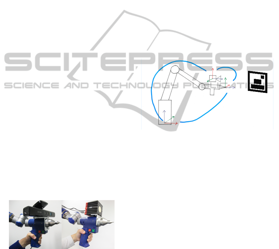
In this paper, we estimate the hand-eye transfor-
mations between a Faro Platinum measurement arm
and depth cameras rigidly coupled to this arm (see
Figure 1). The arm has a measurement range of 3.7
meters. It outputs the position and orientation of
its point tip with a precision of 0.073mm. The ap-
proaches described in this paper are not only applica-
ble for measurement arms, but also for other hand-eye
calibrations, for example between a robot and a depth
camera. As a preparation step, the intrinsic calibra-
tion parameters (focal length, principal point and the
distortion parameters) of the depth cameras were cal-
culated with the GML camera calibration toolbox.
(a) Kinect (b) SwissRanger 4000
Figure 1: Depth cameras rigidly coupled with a Faro mea-
surement arm.
The remainder of this paper is structured as fol-
lows. First, Section 2 and Section 3 describe the 2D
image based and the 3D measurement based hand-eye
calibration approaches. Then, Section 4 introduces
the error metrics for evaluating the hand-eye cali-
brations. The two hand-eye calibration approaches
are evaluated quantitatively in Section 5, both for a
Kinect and a SwissRanger 4000 depth camera. Fi-
nally, conclusions are drawn in Section 6 and possible
adaptations for future work are proposed.
2 2D IMAGE BASED HAND-EYE
CALIBRATION
For a depth camera, the hand-eye transformation can
be estimated in a similar way as for a 2D color cam-
era. In this paper, we use the image based hand-eye
calibration described by Kahn for a depth camera and
an articulated measurement arm (Kahn and Kuijper,
2012). The image based hand-eye calibration is sum-
marized in this section.
p1
p2
p3
p4
WCS
CCS
TipCS
T1
T2
T3
Figure 2: Image based Hand-Eye Calibration (Kahn and
Kuijper, 2012).
Figure 2 visualizes a sketch of the measurement
arm, the depth camera and an image marker which
is used to calculate the hand-eye calibration with this
image based approach. We define the world coordi-
nate system (WCS) as the coordinate system of the
measurement arm. The measurement arm outputs the
transformation T1, which is the relative transforma-
tion between the measurement tip’s coordinate sys-
tem (TipCS) and the coordinate system of the base
of the measurement arm (WCS). The transformation
T2 is the hand-eye transformation between the coor-
dinate system of the depth camera (CCS) and TipCS.
T3 is the camera pose relative to the world coordinate
system. Once the hand-eye transformation is known,
the camera pose can be calculated from the pose of
the measurement arm and the hand-eye transforma-
tion with
R
3
= R
2
· R
1
,
t
3
= R
2
·t
1
+t
2
.
(1)
In the notation of Equation (1), each transforma-
tion Ti is split up into its rotational and translational
component (R
i
and t
i
). The equation used to calculate
VISAPP2014-InternationalConferenceonComputerVisionTheoryandApplications
482

the hand-eye calibration T 2
j
is specified in Equation
(2) (it can easily be inferred from Equation (1)). The
hand-eye transformation is calculated from n pose
pairs (T 1
j
, T 3
j
) with 1 ≤ j ≤ n. Each such pair
contains a pose of the measurement arm’s point tip
and a depth camera pose, both relative to the world
coordinate system. Theoretically, the hand-eye cali-
bration could be approximated by a single pose pair.
However, to improve the accuracy, many pose pairs
are captured and T 2
j
is calculated for each pose pair.
Then, each rotational and translational parameter of
the final hand-eye calibration is the median of this
parameter in all collected T 2
j
transformations. The
median is used to calculate the final hand-eye trans-
formation because it is more robust against outliers
than the mean values.
R
2
= R
3
· R
1
−1
t
2
= t
3
− R
2
·t
1
(2)
Image based Depth Camera Pose Estimation.
The pose of a camera can be calculated from a set
of 2D-3D correspondences. Each such 2D-3D cor-
respondence stores the position of a 3D point in the
world coordinate system and its 2D projection onto
the image coordinate system of the camera. We use
a 2D calibration pattern to obtain such 2D-3D corre-
spondences. Here, the 2D calibration pattern is an im-
age marker which can also be robustly detected with
depth cameras which have a lower resolution than
standard color cameras. This 2D calibration pattern
is attached to a planar surface in the working range of
the measurement arm and the 3D positions of its four
corners (p1, ..., p4) are measured with the point tip of
the measurement arm. The measured 3D coordinates
are in the base coordinate system of the measurement
arm (which is the world coordinate system).
Then, the calibration pattern is detected in the 2D
image captured by the depth camera. Time-of-flight
depth cameras directly measure an intensity (grey)
value for each captured pixel, which can be used to
detect the 2D pattern. In contrast to time-of-flight
cameras, per default the depth camera of the Kinect
only outputs a depth value per pixel and no color or in-
tensity information. However, the Kinect depth cam-
era can be switched from depth to infrared acquisition
mode. Thus, it is possible to detect the calibration pat-
tern in the infrared image of the depth camera and to
estimate the pose of the Kinect depth camera based
on the detected 2D pattern.
The four 2D-3D correspondences (2D point in the
image and the 3D coordinate of the detected 2D point
in the WCS) as well as the intrinsic parameters of the
depth camera and an image of the marker are the input
for the camera pose estimation. The depth camera’s
pose T 3
j
is estimated with direct linear transforma-
tion (DLT) and a subsequent nonlinear least squares
optimization.
3 GEOMETRIC 3D HAND-EYE
CALIBRATION
The principle of the geometric hand-eye calibration
is similar as the image based approach sketched in
Figure 2. Just as for the image based approach, the
transformation T1 is output by the measurement arm
and T3 (the pose of the depth camera in the world co-
ordinate system) is estimated for each single frame.
Then, the hand-eye calibration T2 is estimated from
T1 and T3 as specified by Equation (2). The dif-
ference between both approaches is that for the ge-
ometric approach, the pose of the depth camera (T3)
is not calculated with image based camera tracking.
Instead, it is estimated by geometrically aligning 3D
measurements on the surface of the real calibration
object (captured with a depth camera) with a virtual
3D model of the calibration object. Therefore, the ge-
ometric hand-eye calibration described in this section
requires a 3D model of the calibration object.
Calibration Object and 3D Model. Figure 3
shows a calibration object and a virtual 3D model of
the calibration object. The calibration object was de-
signed such that it accounts for the specific 3D mea-
surement properties of depth cameras (Willert et al.,
2012). The measurement accuracy of depth cameras
depends strongly on the surface of the captured ob-
ject. For instance, at jump edges or on object sur-
faces which absorb most of the light emitted by time-
of-flight depth cameras, the measurement accuracy of
these depth cameras is poor (Piatti, 2011)(Stoyanov
et al., 2012). Therefore, the curved surface of the
calibration object was designed such that no jump-
ing edges occur on its front surface when the depth
camera is moved in front of it. Furthermore, it con-
sists of a material which diffusely reflects most of
the light emitted by time-of-flight depth cameras and
which thus supports the precision of the depth mea-
surements. Additionally, the shape of the calibration
object is designed in such a way that only one unique
3D alignment exists (neither symmetries nor period-
icities).
Alignment of the Virtual 3D Model with the Real
Calibration Object. Before the camera pose can be
estimated with geometric alignment, as a preparation
step, the virtual 3D model needs to be transformed
Hand-eyeCalibrationwithaDepthCamera:2Dor3D?
483

(a) Real 3D calibration object. (b) Virtual 3D model. (c) Virtual 3D model.
Figure 3: 3D calibration object and 3D model of the calibration object, aligned with 3D measurements (red: acquired with
the point tip of the measurement arm, orange: captured with the Kinect depth camera).
such that it has the same position and orientation as
the real 3D calibration object. To align the virtual 3D
model with the 3D calibration object, sparse 3D mea-
surements on the surface of the real 3D calibration
object are acquired with the point tip of the measure-
ment arm. Figure 3(b) shows such 3D points, colored
in red. These 3D points are used for the alignment
of the virtual 3D model with the real calibration ob-
ject. The 3D point cloud and the 3D model are aligned
with the Iterative Closest Point algorithm (ICP)(Besl
and McKay, 1992)(Rusinkiewicz and Levoy, 2001).
We use a point-to-triangle ICP variant which iter-
atively reduces the distances between the 3D point
cloud (measured on the surface of the real object) and
the 3D triangle mesh of the virtual model. First, the
3D point cloud and the 3D model are coarsely aligned
manually. Then, the alignment is optimized with the
ICP algorithm. In each iteration, the closest point on
the triangle mesh is searched for each measured 3D
point. Then, singular value decomposition is used to
estimate a rotation and a translation which transforms
the virtual 3D model, such that the average distance
between both point sets is minimized. This iterative
alignment reduces the average distance between the
3D points (consisting of 80.000 measurements) and
the 3D model shown in Figure 3 to 0.2mm.
Camera Pose Estimation by Geometric Alignment.
The geometric alignment between a 3D point cloud
and a 3D model is computationally expensive. There-
fore, as a preparational step, we create an octree that
hierarchically divides the space around the 3D model
into rectangular regions. This speeds up the detection
of closest points on the surface of the 3D model. Only
those triangles need to be inspected which are located
in the same region of the hierarchical bounding vol-
ume as the 3D point measured with the depth camera.
For each captured depth image, the pose T3 of the
depth camera is estimated with geometric alignment
using the ICP algorithm.
The ICP algorithm requires a coarse initial esti-
mation of the depth camera’s pose. To get such an
initial estimation, we apply the hand-eye transforma-
tion calculated with the image based approach on the
pose T1 of the measurement arm. An equally feasi-
ble approach would be to set the approximate camera
pose for the first frame manually. Then, the hand-
eye calibration calculated geometrically from previ-
ous frames can be used to initialize the camera poses
of all other frames. Given the approximate pose of
the depth camera, the following steps are repeated it-
eratively to improve the camera pose estimation with
geometric alignment:
1. Render the 3D model with the current estimate of
the camera parameters and use the rendered im-
age as a validity filter. Reject all 3D measure-
ments captured at pixels to which the 3D model
does not get projected. This removes 3D mea-
surements which do not belong to the surface of
the calibration object.
2. Use the depth camera’s pose estimation (R,t) with
the following equation to transform each 3D mea-
surements acquired with the depth camera from
the camera coordinate system (p
ccs
) to the world
coordinate system (p
wcs
):
p
wcs
= R
−1
(p
ccs
−t) (3)
3. For each 3D measurement: Find the closest point
on the triangle mesh (the octree speeds up this cal-
culation).
4. Trim the found point pairs to remove outliers: re-
ject those 5% of the found point pairs, which have
the largest distance between the measured and the
found 3D point.
5. Calculate the transformation that minimizes the
distance between both point sets with singular
value decomposition.
6. Update the estimated camera pose by applying the
calculated transformation on the previously esti-
mated camera pose.
Figure 3(c) shows 3D measurements captured
with a Kinect depth camera, geometrically aligned to
the virtual 3D model of the calibration object.
VISAPP2014-InternationalConferenceonComputerVisionTheoryandApplications
484
4 ERROR METRICS
The quantitative evaluation of the hand-eye calibra-
tions is subject to two major challenges:
1. The searched (”correct”) hand-eye transformation
is not known and cannot be measured directly.
2. The ”correct” hand-eye transformation might be
different for 3D measurements than for the 2D im-
ages captured with a depth camera. For example,
the manual of the SwissRanger 4000 depth cam-
era explicitly states that the 3D measurement’s co-
ordinate system is not located at the optical center
of the depth camera (MesaImaging, 2009).
As no ground truth data is available for the hand-
eye calibration, the accuracy of the hand-eye calibra-
tion needs to be evaluated indirectly (without com-
paring the estimated hand-eye calibration to ”correct”
reference values of the calibration). Furthermore, for
applications which use both the 3D measurements and
the 2D images acquired by a depth camera, the accu-
racy of the hand-eye calibration can not be assessed
either with a 2D or with a 3D data based error metric
alone. For these reasons, we use both a 2D and a 3D
data based metric to evaluate the accuracy of the depth
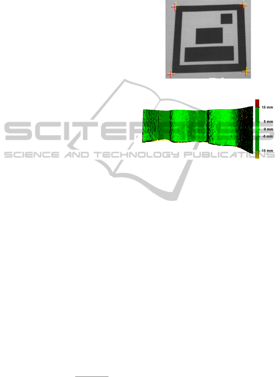
camera based hand-eye calibrations. Visualizations of
both error metrics are shown in Figure 4.
2D Error Metric. We propose to use the ”normal-
ized reprojection error” as 2D error metric. The un-
normalized reprojection error measures the distance
between the projection m of a 3D point M
wcs
to the 2D
image and the detected position of this point in the 2D
image (m
0
). Here, M
wcs
is the 3D position of a corner
point of the 2D calibration pattern, measured with the
point tip of the measurement arm as described in Sec-
tion 2. For each frame of the evaluation sequence, the
pose (R,t) of the depth camera is calculated from the
pose of the measurement arm and the estimated hand-
eye transformation with equation (1). Then, given the
intrinsic camera calibration matrix K, the projection
m of M
wcs
onto the 2D image is calculated with
m = K[R|t]M
wcs
. (4)
The reprojection error increases when the camera
is moved closer to the 2D calibration pattern. Thus,
we normalize the projection error by the length of the
2D calibration pattern, to get the normalized reprojec-
tion error as a percentage of the calibration pattern’s
size. Given the projections m
i
and m
i+1
of two adja-
cent corner points of the calibration pattern, the nor-
malized reprojection error (m
i
, m
0
i
) is:
NReprojErr(m
i
, m
0
i
) = 100 ·
k
m
i
− m
0
i
k
2
k
m
i
− m
i+1
k
2
. (5)
(a) 2D error metric (reprojection error in 2D image). Projected points m
i
(red) and detected 2D points m
0
i
(yellow).
(b) 3D error metric: pixelwise difference between measured and real dis-
tance to the 3D calibration pattern.
Figure 4: 2D and 3D error metrics.
3D Error Metric. As 3D error metric, we use the
distance between the 3D measurements of the depth
camera and the surface of the calibration object. As
described in Section 3, the 3D model used in this work
was aligned with the real calibration project with an
accuracy of 0.2mm. Thus, the 3D model provides
ground truth data for the evaluation of the 3D mea-
surements. To compare the depth measurements with
this ground truth data, the camera pose is first calcu-
lated from the pose of the measurement arm and the
estimated hand-eye calibration. Next, the 3D model is
rendered from the current pose estimation of the depth
camera. Then, the depth buffer values are compared
with the depth values measured by the depth camera.
Please note, that even for a perfect hand-eye cal-
ibration, there are still 3D differences between the
measured and the ground truth distance values. Such
3D differences are for example caused by measure-
ment inaccuracies and systematic measurement errors
of the depth camera. However, the total 3D error
(caused both by inaccuracies in the hand-eye calibra-
tion and by other error sources) increases when the
hand-eye calibration is inaccurate and decreases for
accurate hand-eye calibrations. By using the same
evaluation sequence for both proposed hand-eye cal-
ibration approaches, we are able to directly compare
the accuracy of both hand-eye calibrations.
Hand-eyeCalibrationwithaDepthCamera:2Dor3D?
485

5 QUANTITATIVE EVALUATION
We evaluated the hand-eye calibrations with a struc-
tured light depth camera (Kinect) and with a time-of-
flight depth camera (SwissRanger 4000). The Kinect
calculates distances by projecting an infrared pattern
on the captured scene and by analyzing the distortions
of the projected pattern. It outputs 640 × 480 depth
values. In contrast, the SwissRanger emits infrared
light and measures the time it takes for the emitted
light to return to the camera after it has been repro-
jected by the captured scene. The SwissRanger 4000
provides 176 × 144 depth measurements.
Evaluation Sequences. The calibration and evalu-
ation sequences were captured hand-held, by moving
the measurement arm with the rigidly coupled depth
camera around the calibration objects. The 3D se-
quences were recorded such that most of the front
shape of the calibration pattern was captured: for
frames in which only a small part of the 3D calibration
surface is visible, an unambiguous alignment of the
3D measurements with the 3D shape of the calibra-
tion object can not be calculated. Furthermore, both
for the 2D and the 3D calibration sequences, more
images were captured such that the calibration object
covered a rather large part of the image: both image
based pose estimations as well as 3D depth measure-
ments become less accurate with increased distances.
The 2D calibration was detected in 3410 images of the
Kinect infrared camera and in 5111 images captured
with the SwissRanger 4000. For the geometric hand-
eye calibration, 809 Kinect depth images and 2866
SwissRanger depth images were used.
5.1 Accuracy
The results of the hand-eye calibrations are shown
in Table 1 (Kinect) and in Table 2 (SwissRanger
4000). The SwissRanger captures less 3D measure-
ments than the Kinect and the 2D image is more
blurred and has a lower resolution. Therefore, the
estimated camera poses vary more and the standard
deviation is higher for the SwissRanger than for the
Kinect depth camera.
Table 3 shows the accuracy as evaluated with the
2D evaluation metric (the reprojection error, see Sec-
tion 4). Furthermore, Table 4 provides the results of
the 3D evaluation metric. As noted in Section 4, the
overall accuracy depends not only on the accuracy
of the hand-eye calibration, but also on other factors
such as the measurement accuracy of the depth cam-
era. As the latter depends strongly on the distance
between the camera and the captured object surfaces,
the overall accuracy is specified for different ranges
of measurement distances.
None of the two approaches (image based calibra-
tion and geometric calibration) is clearly more accu-
rate than the other one. With the 2D evaluation metric,
the image based calibration procedure performs bet-
ter than the geometric hand-eye calibration (see Table
3). However, with the 3D evaluation metric, the ge-
ometric hand-eye calibration procedure performs bet-
ter than the image based approach (Table 4). As ex-
plained in Section 4, the origin of a depth camera’s
3D coordinate system is not necessarily at the optical
center of the camera. Therefore, in view of the accu-
racy of the hand-eye calibration for the 3D measure-
ments, the 3D evaluation metric is more conclusive
than the 2D evaluation metric. Thus, the 3D measure-
ment based hand-eye calibration seems to provide a
more accurate hand-eye calibration for the 3D mea-
surements.
Distances in the Calibration Sequences For most
measurement distances, the geometric hand-eye cali-
bration provides more accurate results in view of the
3D measurements than the image based calibration
(see Table 4). However, for very close distances, the
accuracy is lower than with the calibration of the im-
age based approach. This effect is probably caused by
the distribution of the distances in the sequences used
for the hand-eye calibrations. Figure 5 shows the cal-
ibration sequences’ distance distributions of the cam-
era centers to the 2D and the 3D calibration pattern.
The accuracy is best for those distances with most in-
put data. Due to the prerequisites in view of the vis-
ibility and the size of the calibration objects in the
images, the 2D images were captured a bit closer to
the calibration object than the data of the 3D calibra-
tion sequences. This effect is stronger for the Kinect
data because the Kinect cannot measure depth values
for surfaces too close to the camera. In order to ac-
quire depth measurements of the whole 3D calibration
object (without missing surface parts), most Kinect
depth images were recorded with a distance of about
1m. Thus, for the Kinect, the 3D data based hand-
eye calibration is most accurate for those distances at
which the Kinect is best operated (at 1m distance, the
Kinect does not suffer from missing surface measure-
ments and acquires more precise depth measurements
than for larger distances).
Systematic Depth Measurement Errors. Depth
cameras suffer from systematic depth measurement
errors. This effect is shown by Figure 6 and is
stronger for time-of-flight depth cameras than for the
Kinect structured light depth camera. However, these
VISAPP2014-InternationalConferenceonComputerVisionTheoryandApplications
486

Table 1: Kinect: estimated hand-eye transformations (R,t) and standard deviations for Kinect depth camera. The rotation R is
represented by a normalized axis angle, in degrees. The translation t is in mm.
Kinect Image based calibration Geometric calibration
median std median std
R (-0.28, 0.80, 93.07) (0.82, 0.73, 0.22) (0.10, -0.27, -93.03) (0.71, 0.57, 0.47)
t (13.30, -54.42, 80.48) (13.08, 10.10, 7.20) (22.07, -58.04, 93.23) (13.22, 5.76, 8.14)
Table 2: SwissRanger 4000: estimated hand-eye transformations (R,t) and standard deviations for SwissRanger depth camera.
The rotation R is represented by a normalized axis angle, in degrees. The translation t is in mm.
SR4000 Image based calibration Geometric calibration
median std median std
R (1.36, 0.14, 89.87) (7.04, 6.80, 2.03) (0.17, 1.63, 90.10) (1.23, 1.29, 1.08)
t (-11.63, 69.38, 103.68) (18.27, 10.23, 13.00) (-12.50, 40.80, 113.56) (15.93, 31.26, 6.02)
Table 3: 2D error metric: Median of normalized reprojection errors. All values are in percent (ratio of reprojection error to
the size of the 2D calibration pattern in the 2D image).
Distance depth Kinect: image Kinect: geometric SR4000: image SR4000: geometric
camera - surface based calibration calibration based calibration calibration
450-599 1.53 2.95 7.54 10.26
600-749 1.75 2.85 5.59 7.60
750-899 2.08 3.91 4.21 5.37
900-1049 2.34 5.13 3.44 4.08
1050-1199 2.75 6.55 3.29 4.62
1200-1349 2.86 7.77 3.67 5.67
1350-1499 2.96 9.14 4.79 7.21
1500-1649 3.20 10.56 6.21 8.87
Table 4: 3D error metric: Median difference between the 3D measurements and the ground truth (3D position on the 3D
model of the calibration object). All values are in mm.
Distance depth Kinect: image Kinect: geometric SR4000: image SR4000: geometric
camera - surface based calibration calibration based calibration calibration
450-599 3.70 13.01 8.90 19.05
600-749 4.88 12.35 10.17 16.81
750-899 6.87 4.84 11.42 12.58
900-1049 10.84 4.04 10.89 8.60
1050-1199 18.97 8.18 10.63 8.24
1200-1349 26.24 11.61 10.81 9.69
1350-1499 38.26 23.32 7.74 8.41
1500-1649 50.58 35.97 10.83 9.41
systematic errors do not seem to have a strong effect
on the accuracy of the hand-eye calibration, as the 3D
data based hand-eye calibration also provides good
results for the SwissRanger time-of-flight depth cam-
era. This might be due to the symmetry of the system-
atic measurement errors, which might lessen system-
atic effects when aligning the 3D measurements with
the 3D model of the calibration object.
Combined 2D and 3D Calibration. To evaluate
whether the accuracy of the hand-eye calibration
could be improved by combining the image based and
the 3D data based approach, we attached three mark-
ers on the wall above the 3D calibration object. The
size of the markers was chosen such that they were
fully visible when recording a sequence of the 3D cal-
ibration pattern. Then, for each frame, we calculated
the hand-eye calibration both with the 2D images and
Hand-eyeCalibrationwithaDepthCamera:2Dor3D?
487
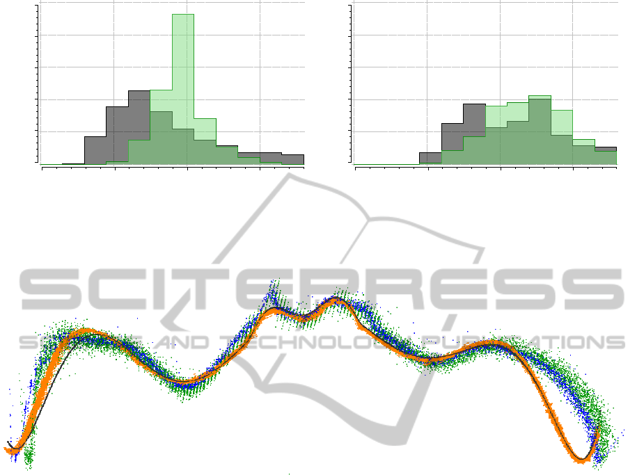
Image based calibration
Geometric calibration
Percentage
0
10
20
30
40
50
Distance (mm)
0 500 1.000 1.500
(a) Kinect hand-eye calibration.
Image based calibration
Geometric calibration
Percentage
0
10
20
30
40
50
Distance (mm)
0 500 1.000 1.500
(b) SR4000 hand-eye calibration.
Figure 5: Distribution of the distances from the camera centers to the calibration objects in the calibration sequences. Grey:
image based, green: geometric.
Figure 6: Curvature of calibration object (black) and aligned 3D point clouds measured by different depth cameras (orange:
Kinect, blue: SwissRanger4000, green: CamCube 3.0). Note the systematic differences of the shape of the real object and the
measured shapes.
with the 3D data. However, this combined approach
neither increased the accuracy of the image based nor
the accuracy of the 3D data based calibrations. The
three markers covered only a rather small area of the
image when both the markers and the 3D calibration
pattern were visible in the same camera image, which
decreased the accuracy of the image based camera
pose estimations. Thus, the estimated camera poses
were too inaccurate to improve the results.
5.2 Processing Time
The hand-eye calibrations were calculated with a 3.07
Ghz processor, using a single-core CPU implemen-
tation. For the Kinect, the estimation of the image
based pose estimations used for the hand-eye calibra-
tion took 18 milliseconds per frame. The 3D data
based camera pose estimations took 167 seconds per
frame. For the SwissRanger 4000, the camera pose
estimation times were 7 milliseconds per frame (im-
age based), respectively 47 seconds per frame (3D
data based).
6 CONCLUSIONS
For depth cameras, the hand-eye transformation be-
tween the camera and a measurement arm can either
be estimated using 2D images or the 3D measure-
ments captured by the depth camera. We have intro-
duced two hand-eye calibration algorithms which dif-
fer only in the way the camera pose is estimated (ei-
ther 2D or 3D data based) and which are thus directly
comparable. These algorithms were evaluated quanti-
tatively, both with a 2D and a 3D evaluation metric.
The quantitative evaluation shows that both meth-
ods provide accurate results. The 3D data based cali-
bration provides more accurate results in view of the
3D measurements. However, this improved accuracy
comes at the cost of the prerequisite of a 3D calibra-
VISAPP2014-InternationalConferenceonComputerVisionTheoryandApplications
488

tion object and its accurate 3D model. Further, the
surface of the 3D model needs to be sampled with the
point tip of the measurement arm in order to align the
3D model and the calibration object. Thus, the 3D
data based approach requires a more labour intensive
preparation than the image based approach (for which
it is sufficient to print a marker and to measure the
four 3D coordinates of its corner points with the mea-
surement arm). Furthermore, the 3D data based hand-
eye calibration is much more computationally expen-
sive than the 2D image based approach. On a CPU,
the computation time is about one day for the 3D data
based approach when 500 Kinect depth images are
used. With the image based approach, the hand-eye
calibration can be calculated in a few seconds. Thus,
the 3D data based approach is well suited for applica-
tions which require precise 3D data. In contrast, the
image based approach is slightly less accurate.
In future work, we will investigate different
shapes of the calibration objects. The 3D calibra-
tion object used in this paper has a non-varying shape
along its vertical axis. During the evaluation, this
turned out to pose difficulties for the geometric align-
ment of the 3D measurements with the 3D model: the
alignment has a degree of freedom along the vertical
axis of the 3D calibration object. Thus, the estimated
alignment can slide along this axis. Therefore, future
3D calibration objects should preferably have a shape
that also varies along the vertical axis. Further, it is
possible to improve the accuracy of the image based
hand-eye calibration by replacing the image marker
with a more diversely textured object, such as a 2D
poster. As the texture of a poster is known before-
hand, it could be used to train sophisticated feature
detection algorithms (Lepetit and Fua, 2006). Such
an algorithm could further enhance the accuracy of
the image based camera pose estimation and thus the
accuracy of the image based hand-eye calibration.
ACKNOWLEDGEMENTS
This work was partially funded by the German Re-
search Foundation (DFG) within the GRK 1362
(http://www.gkmm.tu-darmstadt.de).
REFERENCES
Besl, P. and McKay, N. (1992). A method for registration
of 3-d shapes. In IEEE Trans. on Pattern Analysis and
Machine Intell., volume 14(2), pages 239–256.
Fuchs, S. (2012). Calibration and Multipath Mitigation for
Increased Accuracy of Time-of-Flight Camera Mea-
surements in Robotic Applications. PhD thesis, TU
Berlin, Germany.
Kahn, S., Bockholt, U., Kuijper, A., and Fellner, D. W.
(2013). Towards precise real-time 3d difference de-
tection for industrial applications. Computers in In-
dustry, pages 1–14.
Kahn, S. and Kuijper, A. (2012). Fusing real-time depth
imaging with high precision pose estimation by a mea-
surement arm. In 2012 International Conference on
Cyberworlds (CW), pages 256–260.
Kim, D.-W. and Ha, J.-E. (2013). Hand/eye calibration us-
ing 3d-3d correspondences. Applied Mechanics and
Materials, 319:532–535.
Lepetit, V. and Fua, P. (2006). Keypoint recognition using
randomized trees. Pattern Analysis and Machine In-
telligence, IEEE Transactions on, 28(9):1465–1479.
MesaImaging (2009). SR4000 user manual (version 2.0).
Piatti, D. (2011). Time-of-Flight cameras: tests, calibra-
tion and multi-frame registration for automatic 3D ob-
ject reconstruction. PhD thesis, Politecnico di Torino,
Italy.
Reinbacher, C., Ruther, M., and Bischof, H. (2012). Ronect:
Hand mounted depth sensing using a commodity gam-
ing sensor. In 21st International Conference on Pat-
tern Recognition (ICPR), pages 461–464.
Rusinkiewicz, S. and Levoy, M. (2001). Efficient variants
of the ICP algorithm. In Proc. 3rd Intl. Conf. on 3-D
Digital Imaging and Modeling, pages 224–231.
Stoyanov, T., Mojtahedzadeh, R., Andreasson, H., and
Lilienthal, A. J. (2012). Comparative evaluation of
range sensor accuracy for indoor mobile robotics and
automated logistics applications. Robotics and Au-
tonomous Systems. Online first 10/2012.
Strobl, K. H. and Hirzinger, G. (2006). Optimal hand-eye
calibration. In Proc. of the IEEE/RSJ Int. Conf. on
Intelligent Robots and Systems, pages 4647–4653.
Tsai, R. Y. and Lenz, R. K. (1988). A new technique for
fully autonomous and efficient 3d robotics hand-eye
calibration. In Proc. of the 4th international sympo-
sium on Robotics Research 1998, pages 287–297.
Willert, V., Haumann, D., and Hartkopf, S. (2012). Meth-
ode zur Hand-Auge-Kalibrierung von 3D-Kameras.
EP12190676.2.
Hand-eyeCalibrationwithaDepthCamera:2Dor3D?
489
