
Deformation Method for 3D Identikit Creation
Petr Martínek and Ivana Kolingerová
Department of Computer Science and Engineering, University of West Bohemia,
Univerzitní 22, Plzeň, Czech Republic
Keywords: Mesh, Deformation, Free-Form Shape Deformation, Identikit.
Abstract: An identikit is a model of a head created for a purpose of identification. Nowadays, the police use mostly
2D portrait identification, which is simple but has limited possibilities. Therefore, 3D head models have
started to be used as identikits. In this paper, we propose small improvements of Free-Form Shape
Deformation (FFSD) for 3D identikits creation, which allow modeling new shapes and keeping important
details. With these improvements the FFSD method is able to create various and realistic deformations of a
human head model which are necessary to make and identikit is a bit quicker. The improved method has
been implemented and used in software prepared for the police.
1 INTRODUCTION
The problem of modeling a human head in 3D
according to the original is very important in several
areas: gaming and film industry, medicine and
criminology. In criminology, a portrait of the head
of an offender created according to the eye-witness
is called an identikit. Most of the available software
for identikits works with 2D images. The 2D
identikit has the disadvantage that the offender is
viewed only from the front. It makes impossible to
model some details that may be on the side of the
head. When modeling 2D identikit, the user needs
more imagination, because it is not possible to look
from the side. On the other hand, 2D identikit
construction is already worked out and large
databases exist.
The deficiencies of the 2D identikit led to
attempts to create the identikit in 3D.
This paper suggests to use an improved method
Free-Form Shape Deformation (Yoshizawa et al.,
2002), which allows to model the 3D identikit by
deforming the model consisting of a triangular mesh.
Modifications are oriented to prevent from artifacts
witch might appear in this special FFSD and to
speed up the method. The method has been
implemented, consulted and tested in a close
cooperation with a police department, with their
positive response.
Content of the paper is as follows. Section 2
describes State of the art. Section 3 shows the
original method of Free-Form Shape Deformation.
Section 4 presents improvements suggested in this
paper. Section 5 is devoted to experiments and
results. Section 6 concludes the paper.
2 STATE OF THE ART
There are three basic methods in 3D how to create a
human head model usable as an identikit: a
morphing of other, existing models, a composition
from pieces and a modeling using deformations.
The morphing is a technique, which allows
obtaining new models by an interpolation of two
existing objects (Botsch et al., 2004). The main
drawback of the morphing method for creation of an
identikit is a necessity to work with a large amount
of different models. Human faces are various and
complex. Different models are available, it may
seem easy to create a new face, but it is not easy to
predict the morphing result. On the other hand a
possibility of an easy creation of "random" faces
from existing ones is an advantage.
Next possibility of creating a human head model
is putting previously created parts together
(http://fidentis.cz/). This method has two drawbacks.
First of all a relatively large database is needed. The
problem of creating many varieties of a human face
is present again. The database of particular face parts
can never be complete and thus perfect. Putting
pieces together is the second and a very essential
104
Martínek P. and Kolingerová I..
Deformation Method for 3D Identikit Creation.
DOI: 10.5220/0004669701040111
In Proceedings of the 9th International Conference on Computer Graphics Theory and Applications (GRAPP-2014), pages 104-111
ISBN: 978-989-758-002-4
Copyright
c
2014 SCITEPRESS (Science and Technology Publications, Lda.)

problem.
The third option of how to create a human face is
a model deformation. The model can be quite
general, e.g. a sphere or a previously prepared
human head. It is quite difficult to deform a general-
shape object, because the deformations needed are
too complex. On the other hand, deforming a
previously prepared reference model requires only
small changes. However, to create the reference
model is not very simple, and its quality is
fundamental.
There is a number of different deformation
methods and it is important to choose a suitable one.
Deformation methods are divided into two groups
according to the affected area: local and global.
Global deformation methods do not allow
modeling details. These methods are suitable for
bending, stretching and animating objects. Methods
based on cage or lattice deformations (Botsch et al.,
2010, Ch 9.5.1 and Ch 9.5.2; Tao et al., 2005) and
methods deforming an object using a skeleton
(Yoshizawa and Belyaev, 2007) are main
representations of this group. These methods are not
suitable for an identikit creation due to their inability
model details.
Local deformation methods, as the term implies,
are intended to small changes in the model and
therefore to details modeling. The biggest drawback
of local methods is their incompetence to create
required deformations on more complicated objects
authentically. There are several different approaches
as follows.
The first local approach is based on curve
deformation (Singh and Fiume, 1998) or surface
deformation (Hu et al., 2001). The curve or the
surface lead the deformation or define the surface of
the model. It is important to give a correct number of
control elements. The biggest problem arises during
setting the control points' position and the area of
influence. Curves and surfaces ensure a smooth
transition between the deformed and the non-
deformed model surface. This smoothing limits the
deformation locality.
Deformations using control points are used in
(Yoshizawa et al., 2002; Atrian-Cruz and Tubig;
2013; Botsch and Kobbelt, 2004). Most of these
methods are based on the principle of adding vectors
to the vertices of the mesh. A shift vector is
calculated using a basis function and the position of
a control point relative to the mesh. The methods of
this group often enable to define a control area, a
deformation area and a fixed area, see e.g. (Botsch
and Kobbelt, 2004). Fixed areas are the areas that
are not to be deformed. These methods allow a very
detailed mesh manipulation. The problem here is to
specify a proper number, position and power of
influence of the control points.
Some methods are a combination of both groups,
e.g. (Masuda et al., 2006; Botch et al., 2006;
Yoshizawa et al., 2003). The method (Yoshizawa et
al., 2003) deforms the model by manipulating its
skeleton. This allows global deformations. It is
possible to introduce new branches of the skeleton.
The disadvantage of this method is a need to find a
skeleton and it is difficult to generate new branches.
Methods (Masuda et al., 2006; Botch et al., 2006)
deform a part of the mesh bounded by two areas.
They are rather concentrated on a more correct
deformation then on a modeling of various shapes,
which is not appropriate for the intended identikit
application.
Let us stress identikit creation specifics. For
identikit modeling it is necessary to keep some
details but not to define a fixed area, which reduces
the variability of a method. Such an area has to be
defined for each deformation which is limiting as a
high number of deformations are necessary. The
deformation method must allow creating any shape
intuitively and simply, using a minimal number of
control elements, because the increasing number of
these elements increases the calculation time.
For identikit creation the methods of local
deformations are more suitable as they deform
object using control points. None of the presented
methods satisfies the requirements completely. They
are best met by (Yoshizawa et al., 2002; Botsch and
Kobbelt 2004). The Free-Form Shape Deformation
method (FFSD) (Yoshizawa et al., 2002) was chosen
in this paper as a base for further modification,
because it is more intuitive and easier to use and
improve. The original FFSD method will be
described in the next section, improvements of the
method in section 4.
3 FREE-FORM SHAPE
DEFORMATION (FFSD)
Consider a triangle mesh M = {V, T} where V is a
set of vertices, V
,
. Results of
deformation are dependent on the position of a
control point C and parameters γ,αandε (selected
by the user).
DeformationMethodfor3DIdentikitCreation
105
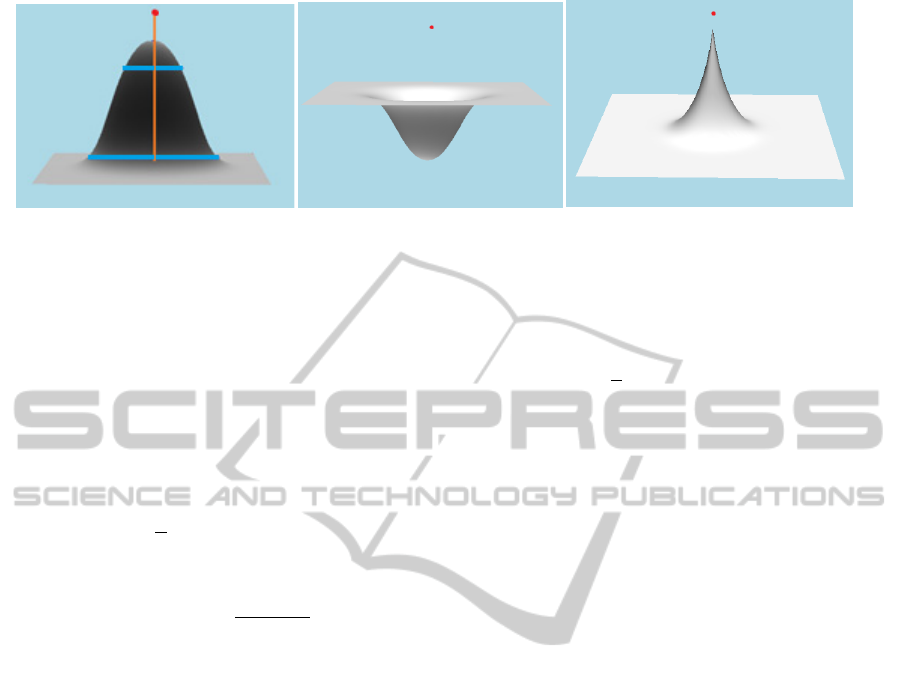
(a) (b) (c)
Figure 1: Deformation of a plane: (a) the parameters γ,αandε, (b) γ positive: deformation is round-repelling (the
deformation is repelling and rounded), (c)γ negative: deformation is sharp-attracting (the deformation is attracting and
sharp). The red point is the control point C.
3.1 Basic Deformation
Given a mesh M = {V, T} as above and a control
point C, let us translate a mesh vertex V
i
into its new
position P
i
defined by
,
,
with the displacement vector d given by
d
C,V
i
γ
σ
W
C,V
i
V
i
‐C
,
(1)
where
,
exp
|
|
2ε
,
σ
,
,
and V
min
is the vertex closest to the control point C,
γ,αandε are parameters. The parameter γindicates
how much the triangle mesh is pulled to the control
point C (see Fig 1), α indicates sharpness of the
deformation (Fig. 1a) and ε determines how large
region is influenced by the deformation (Fig. 1a).
The parameters work as follows. The width of the
upper part of the deformed mesh grows with α, the
width of the lower part with ε. Typical values of
parameters are γ∈ <-1,1>, α∈ <0,1> and ε∈
<0,1>. The displacement (1) is computed for all
mesh vertices V
i
.
3.2 Advanced Set of Controls Point
3.2.1 Virtual Control Point
The basic approach described above allows only
round-repelling and sharp-attracting deformations.
The opposite cases of these deformations are often
needed, too. They are achieved using a virtual
control point V
cp
which is obtained as
,
where V
cp
is used in Eq. 1 instead of C:
,
γ
σ
,
.
(2)
3.2.2 Multiple Control Points
When more control points C are used, the
deformation method is extended to
,
,
(3)
where the sum is taken over all the control points C
k
.
Parameters γ
,α
andε
can be defined for each
control point C
k
.
3.2.3 Directional Deformations
The procedure described above is able to deform a
mesh only in the direction of the distance of the
points C and V
min
. But in order to achieve various
shapes, it is necessary to implement a directional
deformation. Instead of the mesh vertex V
min
closest
to the control point C, we choose a reference point R
(defined by the user). A virtual control point V
cp
is
now defined:
2.
(4)
(4) is to be substituted into Eq. (2). Instead of
W(C,V) is used W(R,V) for directional
deformations. An example of a directional
deformation is shown in Fig. 2. The red control point
C and the green reference point R in Fig. 2 are
selected by the user to achieve the required
directional deformation.
The method FFSD allows also an anisotropic
deformation, but for the purpose of identikit
construction the described deformations are
sufficient.
γ
ε
GRAPP2014-InternationalConferenceonComputerGraphicsTheoryandApplications
106

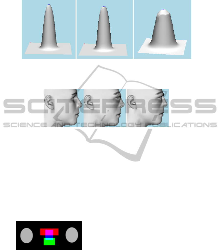
Figure 2: Directional deformations. Examples of directional deformation of plane. Red point is the control point C, the
green point is the reference point R and blue point is V
min
.
4 THE PROPOSED
MODIFICATIONS
OF THE METHOD
To get better, more varied and more correct
deformations for the identikits creation it was
necessary to expand the original method. Critical
deficiencies appeared mainly in the large
deformation of a small region, when peaks arose in
the mesh. These peaks are undesirable for the
identikit creation. Peaks could be repaired by
refining the triangular mesh, but this approach is
very inefficient. Therefore, we added a new height
parameter , which limits the height of the
deformation by the specified value (0,1). It
is true that after the height parameter is used, the
resulting deformation is lower (the top of the
extruded mesh is cut, see example in Fig. 3c) than
the user has intended, but it can be easily dealt by
increasing the parameter γ.
For identikit creation it is necessary to deal with
the following techniques, not supported in the
original method: to translate a part of the face
without a deformation and to preserve detail when
the mesh is deformed. These operations are enabled
by the introduction of the parameter .
We have to multiply the sum in the equation (3)
by the value of L, which represents the reduction:
∗
,
.
(5)
Where the scaling factor L is given by
,
where S
max
is
S
,
∗
and S is
S
,
.
S
max
is the size of a maximum possible displacement
(the distance between C
k
and V
min
) scaled down by
. S is a size of displacement of a mesh vertex V
i
. If
Eq. (5) was used for all mesh vertices. the results
would be still undesirable: deformation would look
almost the same as with Eq. (3), it would be only
smaller. To eliminate the inwanted peaks, we need
to transform only those vertices V
i
which satisfy
relation (6):
|
|
,
(6)
where V
i
new
is the new position of V
i
. V
min
, C
k
, d, V
i
and P
i
have the same meaning as in Section 3.
Examples of the use of the parameter are in
Fig. 3. Figure 3c shows the composition of two
previously impossible deformations.
The advantage of the parameter is its ability to
keep a detail during a deformation. Part of the
triangular mesh, which is located in the area
governed by , retains its original shape. This fact is
very useful in the identikit creation, see Figure 4.
When comparing the images 4b and 4c we see that
figure 4c is more realistic.
Another advantage of the parameter is the
possibility of moving the part of the mesh without
losing its detail or breaking the mesh topology. This
ability is very useful when moving ears and eyes.
In addition to the restriction of the deformation
from above it is possible to restrict the deformation
from below or on both sides. The result would then
be, in the case of restrictions below, only a small
"mound", sharply cropped on the button and in case
of restrictions on both sides only the center of the
affected area would be deformed. For these two
options we have no practical use at present, but we
plan to use them to centre warts.
As described above, the deformation algorithm
works with all mesh vertices for which the
DeformationMethodfor3DIdentikitCreation
107
(a) (b) (c)
Figure 3: Using parameter height: (a) deformation with a peak, (b) the peak eliminated using the parameter (0,9), (c)
example of combined deformations using : a large deformation (extension) restricted by (0,8), followed by a small
deformation (rounded top).
(a) (b) (c)
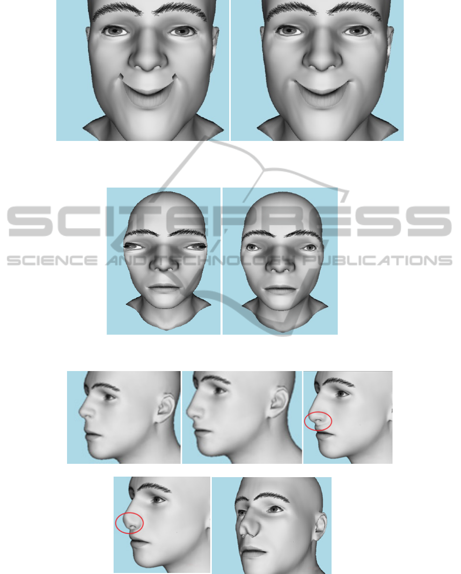
Figure 4: Preservation of the shape of the mesh in the important area of eyes: (a) a reference model, (b) a deformed model
without the use of the parameter , (c) the deformed model using the parameter (0,8).
displacement is computed. This is not necessary
because local deformations significantly influence
only a very small area of mesh. The significant local
deformations include editing tip of a nose, changing
the size of eyes and changing the shape of lobe of
the ear. This led us to introduce an area of influence
defined for particular parts of the face, see Figure 5.
Each deformation is performed only with the
vertices in the area. The introduction of these areas
significantly accelerated the computation. The area
of influence does not change the shape of
deformation, unlike the fixed area.
Figure 5: Areas of influence: ears (grey), mouth (green),
eyes (red), nose (blue).
5 RESULTS
We have created a prototype of a software for an
identikit creation based on the described improved
FFSD method. The software is written in C# using
SlimDX and DirectX 9. The tested model has 13 909
vertices and 83 127 triangles and the tested
deformations use three and more control points.
Tests were performed on Intel Core2 Quad CPU
Q6600 2.4GHz with 4GB RAM. The software is
operated by combined deformations of a basic head
model. The combined deformations are, e.g.,
enlarging of the mouth, ears shift, eyes rotation and
are programmed as macros. Macros define all
necessary control points and parameter values, so
the user does not need to define them. The only
exception is the parameter γ by which the user
controls the size of the required deformation.
Besides macros, the user may do free
deformations by defining control points and
parameters.
For greater clarity the results are presented on
extreme deformations, which borders on caricature.
In real use the deformations are milder.
Most obvious improvement is evident in the
large deformations, such as a big smile in Figure 6.
The expression already reminds a caricature, but as
seen in Figure 6, even such an extreme deformation
can be achieved.
Significant differences are evident in the areas of
a nose and eyes. In these areas it is necessary to keep
details. For example when the size of the nose is
changed, it is important to retain its original shape.
GRAPP2014-InternationalConferenceonComputerGraphicsTheoryandApplications
108
(a) (b)
Figure 6: Big smile: (a) the original method caused a mesh intersection and self-intersection at the corners of the mouth, (b)
the improved method (0,9).
(a) (b)
Figure 7: Eyes shift: (a) the old method - eyes are considerably deformed, (b) the improved method (0,9).
(a) (b) (c)
(d) (e)
Figure 8: Elongation of the nose: (a) a reference model, (b) the correct result achieved by an improved method (0,85)
(c-e) attempts to create a longer nose with the old method. Red ellipses highlight the important areas.
DeformationMethodfor3DIdentikitCreation
109
(a) (b) (c) (d) (e)
Figure 9: Shift of ears: (a) a reference model, (b, c) the old method, (d, e) the new method (0,3).
(a) (b) (c)
(d) (e)
Figure 10: Examples of deformations on the glasses: (a) a reference model, (b) narrow frames, (c-e) a change of the frame
shape.
If not, the user would have to perform some
additional modification to keep the nose shape,
which would be a difficult and time-consuming task.
Figure 7 shows an operation when eyes are shifter
further apart: in the proposed method distortion was
avoided.
Figure 8 shows an elongation of a nose: the
original model (a), the result of the improved
method (8b) and problems with the original method
(8c-e).
Figure 8c shows the influence of a larger area for
the deformation ε, which caused an overlap between
the nose and the upper lip. Figure 8d shows the
influence of a smaller ε which prevents the overlap,
but a peak in the nasal septum appeared. Figure 8e
uses a small ε and more control points, which results
in unrealistically deformed nostrils. In this case the
change of the parameter α is not very helpful either,
because to reduce spikes, it would be necessary to
refine the mesh. Figure 8b shows the use of one
control point and the height parameter, the change
affects a smaller area mesh, thus avoiding an overlap
and the height parameter prevents from peaks and a
loss of the original shape of the nose.
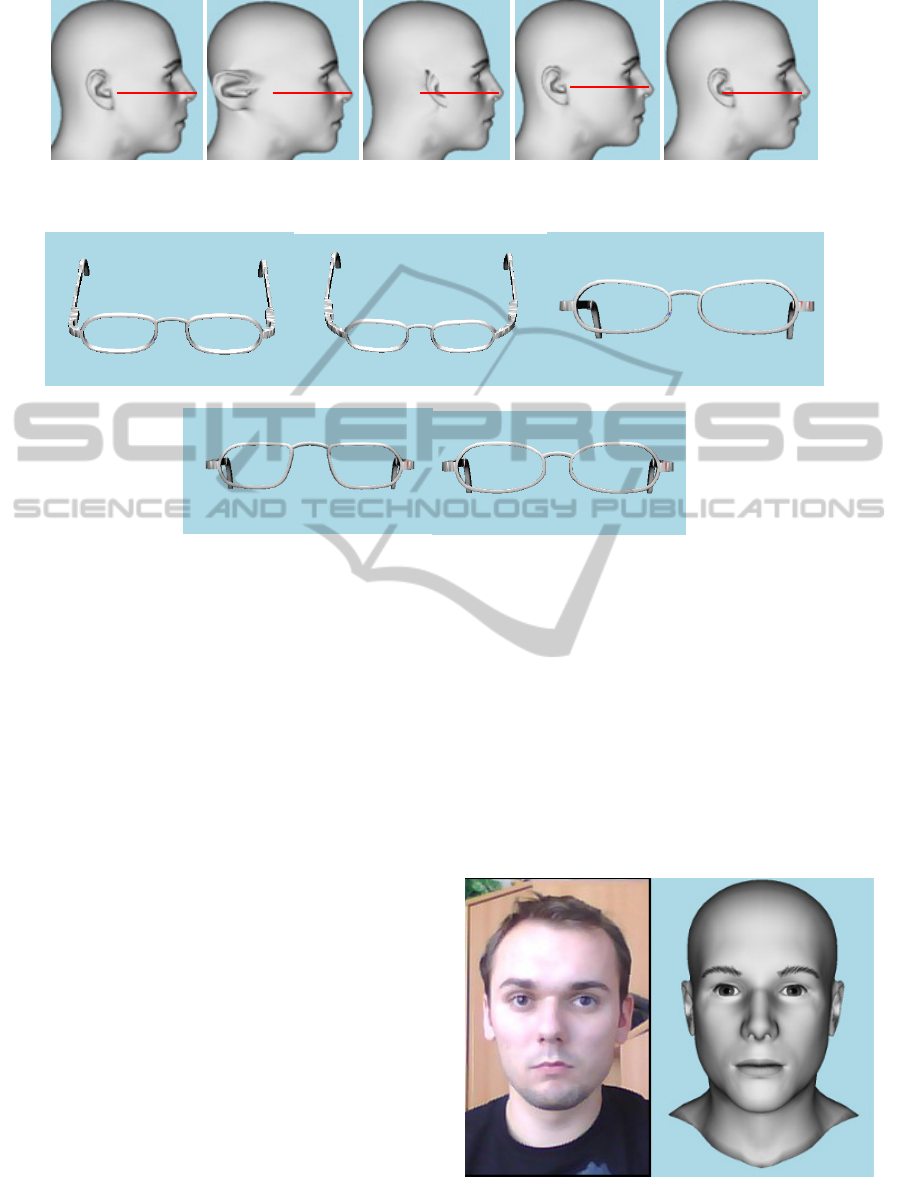
The new method is able to translate larger parts
of the mesh without losing its shape. Figure 9 shows
a shift of the ears. A red line segment of a constant
length is placed in the figure for better
understanding.
Figure 10 illustrates some deformations of
glasses done by the modified method, which were
not possible
with the old method.
After the introduction of areas of influence, some
deformation showed up to 84% speedup, see Table
1. Fig. 11 shows a reference photo and the identikit
of the same person created by our software.
Figure 11: Photo and example of an identikit
GRAPP2014-InternationalConferenceonComputerGraphicsTheoryandApplications
110

Table 1: Runtimes for computation of a deformation with
influence areas.
Deformation
Original
FFSD [ms]
Improved
FFSD [ms]
Speedup
[%]
Change of the
mouth shape
48 24 50
Enlarging of the
mouth
41 16 61
Eyes shift 32 10 69
Ears protrusion 135 21 84
Ears shift 132 28 79
30 predefined
deformations
1281 475 63
6 CONCLUSIONS
In this paper, we presented improvements of the
Free-Form Shape Deformation for identikits
creation. Improvements allow to model new shapes
and transform a part of the mesh without introducing
artifacts and a loss of detail. The modified method
not only did not lose its variability but, vice versa,
its possibilities have been extended. Also a speedup
has been achieved. The modified FFSD was
incorporated into an application which is at present
tested by the police. In the near future, we will
concentrate on modeling of hair, bread, skin and
aging of the models.
ACKNOWLEDGEMENTS
The work was supported by the UWB grant SGS-
2013-029 Advanced Computer and Information
Systems and by Ministry of Education, Youth, and
Sport of Czech Republic – University spec. research
– 1311. We would like to thank the Analytical
Police Department of Czech Republic in Ústí nad
Labem for close cooperation. We are grateful to B.
Podlesák for the glasses model.
REFERENCES
Málková, M., Kolingerová, I., Parus, J., 2008. Core-based
morphing algorithm for triangle meshes. SIGRAD
2008.
Botsch Mario, Kobbelt Leif, Pauly Mark, Alliez Pierre,
Lévy Bruno. Polygon Mesh Processing Ch. 9.5.1.
Lattice-Based Freeform Deformation. A K Peters,
September 22, 2010. ISBN 1568814267.
Botsch Mario, Kobbelt Leif, Pauly Mark, Alliez Pierre,
Lévy Bruno. Polygon Mesh Processing Ch. 9.5.2.
Cage-Based Freeform Deformation. A K Peters,
September 22, 2010. ISBN 1568814267.
Tao, J., Scott S., Warren, J., 2005. Mean value coordinates
for closed triangular meshes. In ACM SIGGRAPH
2005 Papers (SIGGRAPH '05), Markus Gross (Ed.).
ACM, New York, NY, USA, 561-566.
Yoshizawa, S., Belyaev, 2007. Skeleton-based Variational
Mesh Deformations Computer Graphics Forum,
26(3):255-264.
Singh, K., Fiume, E., 1998. Wires: a geometric
deformation technique. In Proceedings of the 25th
annual conference on Computer graphics and
interactive techniques (SIGGRAPH '98). ACM, New
York, NY, USA, 405-414.
S.-M. Hu, Y.-F. Li, T. Ju, X. Zhu, 2001. Modifying the
shape of NURBS surfaces with geometric
constraints, Computer-Aided Design. 33(12):903-912.
Yoshizawa, S., G.Belyaev, A., Seidel, H.-P., 2002. A
Simple Approach to Interactive Free-Form Shape
Deformations, Proceedings of the 10th pacific
conference on computer graphics and applications.
Atrian-Cruz, P., Tubig, P. MeshShop: Free-Form
Deformation and Direct Manipulation. [online]. [cit.
2013-06-24]. Available from :
http://classes.soe.ucsc.edu/cmps160/Spring05/finalpag
es/pati/
Botsch, M., Kobbelt, L., 2004. An intuitive framework for
real-time freeform modeling. In ACM SIGGRAPH
2004 Papers (SIGGRAPH '04), Joe Marks (Ed.).
ACM, New York, NY, USA, 630-634.
Masuda, H., Yoshioka, Y., Furukawa, Y., 2006.
Interactive mesh deformation using equality-
constrained least squares. Comput. Graph. 30, 6
(December 2006), 936-946.
Botsch, M., Sumner, R., Pauly, M., Gross, M., 2006.
Deformation Transfer for Detail-Preserving Surface
Editing, In Vision, Modeling & Visualization (2006),
pp. 357-364.
Yoshizawa, S., G.Belyaev, A., Seidel, H.-P., 2003. Free-
form skeleton-driven mesh deformations.
In Proceedings of the eighth ACM symposium on Solid
modeling and applications (SM '03). ACM, New
York, NY, USA, 247-253.
Fidentis. [online]. [cit. 2013-06-24]. Available from:
http://fidentis.cz/
DeformationMethodfor3DIdentikitCreation
111
