
Nonlinearities and their Distortion Effects in COherent-OFDM
Systems
Gábor Fekete and Tibor Berceli
Department of Broadband Infocommunications and Electromagnetic Theory, Budapest University of Technology
and Economics, Egry József utca 18, Budapest, 1111 Hungary
Keywords: Coherent Optical System, OFDM, Mach-Zehnder Modulator, Dispersion, Fiber Nonlinearity, CO-OFDM,
Heterodyne Detection, 16-QAM.
Abstract: Nonlinear Mach-Zehnder Modulator and single mode fiber distort the transmitted signal. Their distortions
were examined with VPIphotonics and the results of the two cases were compared with each other. It is
important to know which element has higher effect to signal. Orthogonal Frequency Division Multiplexing
modulation was used because next generation optical network will use this modulation form.
1 INTRODUCTION
Orthogonal Frequency Division Multiplexing
(OFDM) is extensively used in electrical domain.
Wi-Fi routers, terrestrial TV broadcast (in Europe)
and so many other applications use OFDM
modulation because the distortion of the channel (i.e.
fading) can be easily compensated by DSP (Digital
Signal Processing). The drawbacks of OFDM are the
sensitivity for nonlinearity in the signal transmission
and the high PAPR (Peak to Average Power Ratio).
The optical systems require a higher-order
modulation format with high capacity because of the
amount of transmitted data is growing rapidly.
OFDM modulation can solve the problem as it did in
the electrical domain. However, the structure of the
optical systems, which use OFDM modulation, are
more complex, because the phase cannot be detected
directly with a photodiode.
In this paper we give a short overview of the
OFDM method in section 2. The coherent optical
OFDM (CO-OFDM) transmission system is
presented in section 3, which is simulated by the
VPI TransmissionMaker (VPI). Our study focuses
on the distortion of the nonlinear Mach-Zehnder
Modulator (MZM) and the signal degradation which
is caused by nonlinearities of Single Mode Fiber
(SMF). We investigate whether their distortion
effect is the same and which has stronger influence
on the transmitted signal.
Figure 1: Theoretical implementation of OFDM
modulation. (Shieh, 2011).
2 PRINCIPLE OF OFDM
OFDM is a special class of multi carrier modulation.
Figure 1 shows its theoretical implementation. This
structure contains a lot of oscillators and filters on
both transmitter and receiver sides. The transmitted
signal is represented as (Shieh, 2011):
skk
i
N
k
skki
Ttiftfjts
iTtscts
sc
0)2exp(
1
(1)
N
sc
is the number of the subcarriers, c
ki
is the i
th
information symbol at the k
th
subcarrier, s
k
is the
waveform of the k
th
subcarrier, T
s
is the symbol
period, f
k
is the frequency of the subcarrier. The
optimum detector can be a matched filter or a
correlator. The detected information of a subcarrier
is given by (Shieh, 2011):
47
Fekete G. and Berceli T..
Nonlinearities and their Distortion Effects in COherent-OFDM Systems.
DOI: 10.5220/0004669900470050
In Proceedings of 2nd International Conference on Photonics, Optics and Laser Technology (PHOTOPTICS-2014), pages 47-50
ISBN: 978-989-758-008-6
Copyright
c
2014 SCITEPRESS (Science and Technology Publications, Lda.)

dttfjiTtr
dtsiTtrc
s
s
T
ks
T
kski
0
0
'
)2exp(
(2)
The subcarriers are orthogonal to each other. Its
result is that the spectrum of the OFDM signal is
smaller than a traditional multicarrier multiplexed
signal because the channels can be overlapped. The
channels are orthogonal to each other if:
,...3,2,1;
1
m
T
mff
s
lk
(3)
OFDM modulation/demodulation can be done by
Inverse Discrete Fourier Transform (IDFT)/ Discrete
Fourier Transform (DFT), which costs less than
using huge number of filters and oscillators (Figure
1). A typical OFDM transmitter can be seen in
Figure 2. Data stream is split up N
sc
part by a serial-
to-parallel converter, and the next block creates the
transmitted symbols of the subcarrier from the bit
sequence. OFDM modulation is made by the IDFT
block. If the subcarriers are not orthogonal to each
other (i.e. there is synchronization failure), ISI (Inter
Symbol Interference) and ICI (Inter Carrier
Interference) will appear in the demodulated signal.
This can be avoided if Guard Interval (GI) is
applied. It is also called as Cyclic Prefix (CP). A
small time period from the end of symbol is copied
down. This is the CP and it is placed at the
beginning of the symbol. Until the time difference
between the subcarriers is smaller than the GI there
will not be ISI and ICI in the demodulated signal.
After GI is added to the signal, its digital samples
are converted into an analogue signal. The optical
carrier is modulated by it. The structure of an
OFDM demodulator is similar to Figure 2 but the
signal flow is reversed so there is a DFT block
instead of the IDFT and it is extended with a clock
restore or synchronization block.
Figure 2: Baseband OFDM transmitter. OFDM
modulation is created by IDFT. (Shieh, 2011).
Transmitters and receivers need to have huge
dynamic range if the PAPR is high. It is not possible
to create a device which has large and linear
Figure 3: Block scheme of the simulated CO-OFDM
system in VPI.
dynamic range. Therefore the value of PAPR must
be decreased by coding technique or clipping. The
clipping method is usually used, which cuts off the
level of the signal above a given value. However,
this increases the noise level outside of the signal
spectrum.
3 SIMULATION
Simulations were made in VPIphotonics (VPI).
Block diagram of our transmission is shown in
Figure 3. Pseudo random bit sequence with 80Gbps
data rate was used in the simulations. OFDM coder
used 16-QAM modulation and created separately the
real (I) and imaginary (Q) parts of the OFDM signal.
There is no 90° phase shift between I and Q. The
laser signal is modulated separately by I and Q
signals. Mach-Zehnder Modulators (MZM) are
applied which have sinusoidal transfer characteristic.
They are biased at the quadrature point, where the
transfer characteristic is linear. I and Q arms are
summarized by an optical coupler. Its behaviour is
similar to an electrical one. The input signal
intensity from both input ports is halved at the
output and it creates 90° phase shift between the
input ports signals. It means that the necessary 90°
phase shift is done by the coupler. So the optical I-Q
modulator is built up by two MZMs and an optical
coupler. After the coupler a standard Single Mode
Fiber (SMF) is placed, when its distortion is
examined. In the other cases it is left out from the
network. Signal detection is based on the heterodyne
detection method. There is a small frequency
difference (Δf) between the laser on the transmitter
side and the laser on the receiver side. It causes that
the detected signal (at the output of photo diodes) is
converted down at Δf frequency. This signal is
demodulated by the OFDM decoder. The analyzer
shows the constellation diagram of the detected
signal. In this article we focus on the nonlinearity of
MZM and SMF. The linewidth of the applied lasers
PHOTOPTICS2014-InternationalConferenceonPhotonics,OpticsandLaserTechnology
48
were 10 kHz. It means that the simulation contains
the effect of the phase noise.
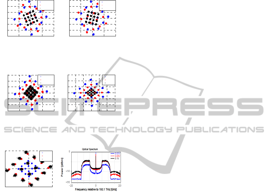
Figure 4: (a) Constellation turns right, if the bias error is
positive and it turns left (b) when the bias changes
negatively.
Figure 5: Asymmetrically biased MZMs. (a) Both MZMs
are biased at the same arm. (b) MZMs are biased at
different arms and the phase change has opposite sign.
Figure 6: (a) Larger drive amplitude increases the distance
between symbols but (b) outside of the OFDM spectrum
the noise level also increases.
3.1 Distortion of Mach-Zehnder
Modulator
Two arms of the MZMs can be driven independently
from each other in VPI. The relation between arms
can be positive or negative. If it is positive then the
sign of phase change is the same in both arms. In the
other case the sign of the phase change is opposite.
Figure 4 shows those cases when MZMs upper arm
are driven. MZMs are biased with 0.5V, which
causes 90° phase shift (optimum point) in the
controlled arm. Both MZM bias points are similarly
changed. If the phase delay is less than 90°, the
constellation is turned clockwise (Figure 4b). It is
rotated the opposite way (Figure 4a), when the phase
shift is more than 90°. This rotation can be
compensated by DSP after detection. Another way
to eliminate this rotation is the differential driving of
MZMs. In this case only the distance between
constellation points will decrease when the bias
changes (Figure 5a). However, the standard
deviation of constellation points is growing linearly
(Table 1).
There is another MZM driving method when one
MZM is driven in the upper arm and the other is
driven in the lower arm with negative sign of phase
changes. It does not cause any difference in the
output light intensity but the electrical field is
different. Between the electrical fields there is a 90°
phase difference. The optical coupler which
summarizes the I and Q signals (Figure 3) also
makes 90° phase shift between them. Its result is that
if MZMs are biased at the optimum point, there will
be no carrier in the transmitted spectrum. In this case
we need an outside clock signal to demodulate the
received signal which highly complicates the
receiver. It can be avoided, if MZMs are not driven
in the optimum point. Slightly shifted from the
optimum the carrier will appear in the spectrum but
the symbols will be closer to each other as Figure 4
shows it. Figure 5b shows the received constellation
when MZMs are driven asymmetrically (same bias
point but the sign of the bias change is the opposite).
This driving method minimizes the rotation of the
constellation. The standard deviation of symbols
does not increase outside from the optimum point of
operation.
Larger drive amplitude increases the distance
between the symbols of the constellation (Figure 6a)
but it does not grow linearly. It has saturation
because of the MZM sinusoidal characteristic. Large
drive amplitude causes bigger standard deviation of
the symbols, too. 0.05V and 0.1V drive amplitude
are near to the saturation point because the distance
between the symbols changed minimally but the
standard deviation of the symbols is twice as big.
Between the two constellations there is a 3.8° angle.
The noise level also increases outside of the signal
spectrum (Figure 6b). It comes from the clipping and
nonlinearities. This growing noise is harmful in
WDM systems, because the channels have to be
placed far from each other.
3.2 Fiber Nonlinearity
Signal shape mainly degrades by the fiber
dispersion. Chromatic dispersion (CD) is the
significant effect in SMF. It rotates the constellation
and spreads the symbols (Figure 7a). Constellation
of the received signal will be a circle because of the
dispersion (Figure 7b). CD has much stronger effect
on the transmitted signal than the MZM. 6km fiber
-2 -1 0 1 2
-1.5
-1
-0.5
0
0.5
1
1.5
Real
Imaginary
optimum
+0.01V
+0.05V
-2 -1 0 1 2
-1.5
-1
-0.5
0
0.5
1
1.5
Real
Imaginary
optimum
-0.01V
-0.05V
-2 -1 0 1 2
-1.5
-1
-0.5
0
0.5
1
1.5
Real
Imaginary
optimum
0.01V
0.05V
-3 -2 -1 0 1 2 3
-3
-2
-1
0
1
2
3
Real
Imaginary
0.01V
0.02V
0.05V
-5 0 5
-5
0
5
Real
Imaginary
0.01V
0.05V
0.1V
a)
b)
a) b)
a)
b)
NonlinearitiesandtheirDistortionEffectsinCOherent-OFDMSystems
49
rotates the constellation with angle of 8°. It is twice
larger than the rotation caused by differential driving
of the MZM.
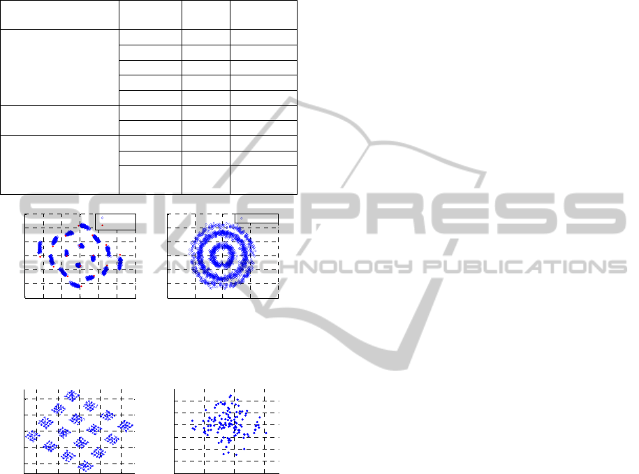
Table 1: Rotation of the constellation.
MZM’s driving
method
Bias [V]
Angle
[deg]
Deviation
at the same
optimum 0 0.024
+0.01 25 0.024
+0.05 -26 0.024
-0.01 -25 0.023
-0.05 26 0.024
differential
0.01 0.2 0.028
0.05 1 0.048
differential, phase
change in the
MZM’s arm is
opposite
0.01 0 0.037
0.02 0.9 0.029
0.05 3.6 0.025
Figure 7: (a) Dispersion spreads the symbols and rotates
the constellation. (b) Constellation diagram after 50km
fiber, if dispersion is not compensated.
Figure 8: (a) Symbol deviation caused by SPM and FWM.
(b). Only FWM caused symbol spread at one symbol.
Dispersion can be compensated by DSP or
Dispersion Compensation Fiber (DCF). Doing it by
DSP is much comfortable because it can be done
electronically beside doing other signal processing
steps. Using of pilot tones this rotation can be
calculated and the correction also can be done. Four
wave mixing (FWM) and self-phase modulation
(SPM) make smaller signal degradation than CD.
Their effect can be seen if the fiber dispersion is set
to zero. Laser power was 20W and fiber length was
50km. Increasing the laser power will not improve
the quality of transmission. Noise level increases
outside of the OFDM spectrum because of FWM.
Constellation symbols highly spread and it seems
they contain the full constellation diagram in small
size (Figure 8a). This kind of modulation mainly
comes from the SPM and in smaller extent from the
FWM. Decreasing the laser power the SPM effect
will be negligible and FWM will be dominant. FWM
causes ICI and it spreads the symbols along both
axes (Figure 8b). It is similar to the effect of white
noise. Standard deviation is 0.0472 which is twice as
much as that one caused by the MZM.
4 CONCLUSIONS
MZM and SMF have quite the same distortion
effects. Both rotate the constellation but the CD
influence on the degradation is much stronger and it
highly spreads the symbols. These rotations can be
compensated by the same algorithm because of the
similarity. The rotation caused by MZM can be
easily eliminated by differential driving. It
minimizes the rotation but the standard deviation of
symbols is increased slightly. If the electrical field of
MZM provides opposite rotation this effect does not
exist and the rotation stays small. Dispersion
compensation always needs additional equipment. It
can be done electronically using a DSP after
demodulation. Other nonlinearities of SMF (i.e. four
wave mixing, polarization mode dispersion) cause
smaller distortion and they are covered by the
distortion effect of MZM nonlinearity and CD. We
usually use low laser power so only FWM will
influence the transmission. Its effect has to be
compensated by a DSP.
REFERENCES
William Shieh, 2011, OFDM for Flexible High-Speed
Optical Networks, Journal of Lightwave Technology,
Vol. 29, No. 10.
W. Shieh, H. Bao, and Y. Tang, 2008, Coherent optical
OFDM: theory and design, Optics Express, Vol. 16,
No. 2,
Jean Armstrong, 2009, OFDM for Optical
Communications, Journal of Lightwave Technology,
Vol. 27, No. 3.
H. Louchet, A. Richter, 2007, Novel Scheme for High Bit-
Rate Coherent OFDM Transmission without PLL,
ECOC.
William Shieh, Ivan Djordjevic, 2010, Orthogonal
frequency division multiplexing for optical
communication, Academic Press, London.
-3 -2 -1 0 1 2 3
-3
-2
-1
0
1
2
3
Real
Imaginary
6km fiber
ideal
-4 -2 0 2 4
-3
-2
-1
0
1
2
3
Real
Imaginary
50km fiber
-2 -1 0 1 2
-2
-1
0
1
2
Real
Imaginary
2 2.1 2.2 2.3
-0.1
-0.05
0
0.05
0.1
0.15
0.2
Real
Imaginary
a)
b)
PHOTOPTICS2014-InternationalConferenceonPhotonics,OpticsandLaserTechnology
50
