Automatic Fly-through Camera Animations
for 3D Architectural Repositories
Patrick Kn
¨
obelreiter
1
, Ren
´
e Berndt
1,2
, Torsten Ullrich
1,2
and Dieter W. Fellner
2,3
1
Institut f
¨
ur ComputerGraphik und WissensVisualisierung, Technische Universit
¨
at Graz, Graz, Austria
2
Fraunhofer Austria Research GmbH, Graz, Austria
3
GRIS, TU Darmstadt & Fraunhofer IGD, Germany
Keywords:
Camera Path Generation, Fly-through Animation, Space Exploration.
Abstract:
Virtual fly-through animations through computer generated models are a strong tool to convey properties and
the appearance of these models. In, e.g., architectural models the big advantage of such a fly-through animation
is that it is possible to convey the structure of the model easily. However, the path generation is not always
trivial, to get a good looking animation. The proposed approach in this paper can handle arbitrary 3D models
and then extract a meaningful and good looking camera path. To visualize the path HTML/X3DOM is used
and therefore it is possible to view the final result in a browser with X3DOM support.
1 INTRODUCTION
Fly-through animation are often used nowadays. With
modeling tools like Maya, Blender, etc. it is possi-
ble to model good looking animations through a 3D
scene. However, this task is very time consuming and
one needs to know how to work with such modeling
tools, in other words: experts are required. Hence,
in this approach it is tried to compute a path through
an arbitrary 3D scene automatically. There should be
no requirement on the actual model like water tight
or manifold. The algorithm should be able to handle
arbitrary models. However, after a path has been cal-
culated it is necessary to visualize the result. Most
often specialized software is used to visualize such
animations. But in this approach no external soft-
ware has to be used. The whole path is exported to
HTML/X3DOM and therefore it is possible to visu-
alize the fly-through animation with a common web
browser with X3DOM support.
This paper is divided into five parts. In the first
section the related work in automatic camera control
will be reviewed. The second section will describe the
general problem of path extraction in a 3D scene and
state properties, which the extracted path should have.
In the third section a detailed description of the algo-
rithm is provided. The fourth section describes how
the extracted path can be used to show a 3D scene
with HTML/X3DOM using the computed path. Fi-
nally, the fifth section will review and summarize the
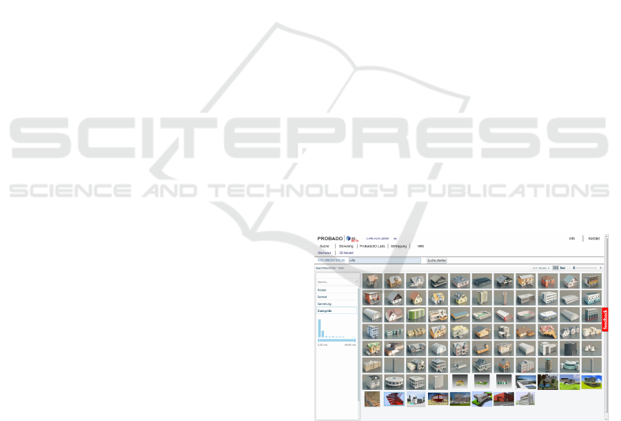
Figure 1: The appealing presentation of retrieval results is
an important task of every 3D shape repository.
work.
The application case of automatically generated
camera animations arises in the context of 3D shape
repositories. The number of collections with 3D ob-
jects are rapidly increasing. Besides collections based
on social collaboration like the Trimble 3D Ware-
house (formerly Google 3D Warehouse), which is an
accompanying website for SketchUp where model-
ers can upload, download and share three dimensional
models (Trimble 3D Warehouse, 2013), or the Shape-
ways 3D parts database (Shapeways, 2013), which
provides a place for exchanging models for 3D print-
ing, also libraries or public institutions are build-
ing up their own collections. For instance, building
authorities are setting up collections of 3D models
335
Knöbelreiter P., Berndt R., Ullrich T. and W. Fellner D..
Automatic Fly-through Camera Animations for 3D Architectural Repositories.
DOI: 10.5220/0004670303350341
In Proceedings of the 9th International Conference on Computer Graphics Theory and Applications (GRAPP-2014), pages 335-341
ISBN: 978-989-758-002-4
Copyright
c
2014 SCITEPRESS (Science and Technology Publications, Lda.)

due to the conceptual shift from using traditional 2D
CAD drawings towards 3D models within the build-
ing and construction industry sector. The arising chal-
lenges for architectural 3D collections have been ad-
dressed by a number of projects, e.g. MACE and
PROBADO. MACE is a former EU-funded project
(2006-2009) that aims to connect and improve acces-
sibility of various repositories of architectural knowl-
edge and enrich their contents with metadata (Meta-
data for Architectural Contents in Europe, 2006).
PROBADO was a project funded by the German Re-
search Foundation (2006-2011). Amongst others, its
goal was to integrate 3D architectural models into the
librarian process chain, starting with acquisition over
indexing up to presentation/delivery (Berndt et al.,
2010). Figure 1 shows the resulting visualization of
a key-word search. Current activities like the DU-
RAARK (Durable Architectural Knowledge) project,
which just started in 2013, concentrate on the long-
term preservation aspects of architectural 3D content
(Durable Architectural Knowledge, 2013).
The appealing presentation of retrieval results of
the main field of applications for our presented ap-
proach – an automatic camera animation, which is
generated during the indexing process of a repository.
2 RELATED WORK
Drucker and Zeltzer described a framework for ex-
ploring intelligent camera controls in a 3D virtual en-
vironment. They did not allow arbitrary 3D mod-
els, but their algorithm is constraint to indoor scenes
where solely a path from one room to another room is
computed in a virtual museum application (Drucker
and Zeltzer, 1994). They used the A* algorithm based
on (Hart et al., 1968) and the Manhattan (L
1
) distance
as a metric.
Argelaguet and Andujar (2010) focused on the is-
sue of computing the ideal speed of the animation
depending on the coherency of consecutive frames
to provide non-fatiguing, informative, interestingness
and concise animations. However, the camera path to
be used was given and not computed automatically.
Hence, their work allows arbitrary scenes, but the ac-
tual camera path is defined manually.
Santos and Duarte generated a graph of valid po-
sitions in a building using an adapted version of the
probabilistic road map generation algorithm proposed
by (Salomon et al., 2003). They used this graph to
guide a user through an unknown building using an
appropriate animation of the camera (dos Santos and
Duarte, 2011).
Ahmed and Eades (2005) described an algorithm
to compute a smooth transition of the camera from
one target node in a graph to another. However, they
mainly addressed Focus+Context issues involved in
navigating large graphs in 3D.
Stoev and Straßer (2002) proposed a method to
compute “good” views of a given data set not only
based on the projected area, but also on the depth of
a specific view. These views are used to generate a
camera path out of it. They tested their approach for
historical data sets like terrain models.
One group of automated camera control ap-
proaches are the visual servoing approaches, which
are a type of reactive approaches, since they react on
changes. These approaches are computationally effi-
cient and thus also suitable for highly dynamic envi-
ronments. E.g., such approaches can be used to follow
a person in a computer game, while avoiding obsta-
cles and occlusions (Espiau et al., 1992) and (Courty
and Marchand, 2001).
Another group of automated camera control ap-
proaches are the pure optimization based approaches.
There, shot properties are expressed as objectives,
which are maximized with classical determinis-
tic (gradient based, Gauss-Seidl, etc.) and non-
deterministic (such as genetic algorithms (Oliver
et al., 1999), Monte Carlo based, etc.) optimization
algorithms.
Christie et al. (2005) extended the work of (Oliver
et al., 1999) for a dynamic camera, where the con-
trol points of a quadratic spline curve are optimized.
However, they used a fixed look-at point and also
known start and end-position of the camera path.
Viola et al. (2006) and (Sokolov et al., 2006) tried
to characterize cognitive aspects such as scene under-
standing and attention. The former work showed how
to compute a set of characteristic views of a scene,
where the latter focuses more on scene understand-
ing. They generated automatic camera paths too. To
do so, they used a heuristic optimization technique
that relies on a local neighborhood search, where they
try to attract the camera to unexplored areas of the
scene.
Representative of the class of constrained based
automated camera control approaches are (Jardillier
and Langu
´
enou, 1998) and (Christie et al., 2002). In
the approach of Jardillier et al. the path of the camera
is created by defining a set of properties on the desired
shot. Christie et al. proposed enhancements in terms
of more expressive camera path constraints.
Since pure optimization techniques and also pure
constraint based approaches have some drawbacks,
some works try to combine these two techniques; see
(Christie and Olivier, 2009).
A definition of viewpoint quality with respect to
GRAPP2014-InternationalConferenceonComputerGraphicsTheoryandApplications
336
scene understanding is given in (Sokolov and Ple-
menos, 2005). An overview and a complete survey on
camera control in computer graphics is also provided
in (Christie and Olivier, 2009).
3 PATH EXTRACTION
The problem to be solved is to generate a meaning-
ful path through a 3D model. In a trivial solution,
this could be done by simply computing the bounding
volume of the model and then fly above the bound-
ing volume in a circle around it. In this case, one do
not have to bother about collisions with geometry or
continuity of the path. However, in most cases such
a solution would not be entirely satisfactory. There-
fore, it seems to be plausible to define some properties
which should be fulfilled by the extracted path.
(1) Meaningful Starting Point
The startposition of the animation should be de-
fined, such that the viewer gets an overview of the
whole model. By satisfying this property, it is en-
sured, that it is easy for the viewer to see where he
is and that he gets a meaningful first impression of
the model.
(2) Overview
A good overview gives the viewer the chance to
explore the global structure of a model. By satis-
fying this property, it is ensured, that the viewer
is not confronted with details of the model, when
the viewer does not even know what the model is
about.
(3) Points of Interest (POIs)
The path should be defined in such a way, that
prominent points are captured in the path. POIs
should emphasize the highlights of a model. This
property is very important in terms of showing
what a specific model distinguishes from another
one.
(4) Look Inside
After the viewer knows enough about a model, the
path should go into the model, if the model has
a proper model-type (see Section 4.3). Here, it
is important that the path uses doors as a human
would do it.
This list encodes also the ordering of the properties.
It is important to give the user the chance to under-
stand the model completely. This is possible by start-
ing with the whole model and give an overview and
then go to details.
4 ALGORITHM
In this section the main algorithm is described in de-
tail. The algorithm is divided into two main parts:
preprocessing and path extraction. In the preprocess-
ing step the algorithm calculates
• Bounding volume of the scene
• Start position
• Points of interest (POIs)
and in the path extraction step all the precomputed
information will be used to compute the actual path
of the animation.
4.1 Preprocessing
In the preprocessing step, all the necessary informa-
tion about the model is acquired, which is then used
later in the path extraction step. All the preprocessing
steps are described in detail.
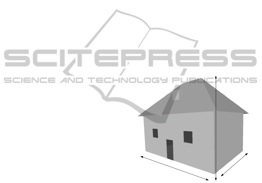
width
length
height
Figure 2: The inner structure of an arbitrary building in a
shape repository is usually unknown, i.e. it cannot be ex-
tracted automatically. Therefore, only a few parameters can
be used, namely length, width, and height of a model.
4.1.1 Bounding Volume Calculation
The bounding volume of a 3D model is very impor-
tant for the path extraction. It defines in which re-
gion the actual geometry is located within the scene.
Additionally the bounding volume encodes the cen-
ter, the width, length and height of the model. All
this information is helpful and can be used in the path
extraction step. Note, that the calculation of length,
width and height is dependent on the up-vector of the
model. The terms length, width and height are defined
as shown in Figure 2.
AutomaticFly-throughCameraAnimationsfor3DArchitecturalRepositories
337

4.1.2 Points of Interest (POIs)
What are POIs? This question is difficult to answer,
because it is a rather subjective which points or places
are interesting for someone or not. However, if we
take a look in real life, there are places around the
world, where many photographs are taken and oth-
ers where no photos are taken. Hence, there are POIs
all around and they show the highlights of a region.
The question is, how POIs can be derived just by us-
ing the geometry without any additional information.
One could argue, that POIs must be present, if there
is a lot of geometry at a position. However, this is
not true, because it is often the case, that very small
things are modelled with a high number of triangles as
it is for example with a fancy door handle. So there is
the need for some other property of the model which
defines POIs. By a more thorough investigation of
what POIs are, it turns out, that the height of POIs is
most often significantly higher than by normal points.
Hence, in this algorithm points which are significantly
higher than the average point-height are considered to
be POIs. This is a reasonable property, because by
looking, e.g., to a cathedral, one would like to see the
clock-tower in detail, because it is so impressive. An
other example, if the scene describes a bigger area like
a city, one want to see the highest buildings. Hence
POIs are extracted using the following Equation (1):
poi = {x
i
: height(x
i
) > 0.95 · height(x
max
)} (1)
where x
max
is the point where the height is maximal.
In theory, this seams to be a very good property.
However, in practice this can only be used very care-
fully. Therefore, some further restrictions on POIs are
defined:
(1) Define minimal distance between POIs
This property restricts POIs to be not to close to
each other.
(2) Two POIs must not have the same hight
This property is very useful in architectural mod-
els as described later. Additionally the number of
points with equal hight are counted.
(3) Define an expected number of POIs to be found
It is not enough to specify a hard threshold as in
(1), because then important POIs might be missed.
Note: This property is just used if the model type
is considered to be an area and not an architectural
model
But why are these restrictions necessary? Consider
an architectural model with a flat roof. With the POI
computation using Equation (1), all points on the roof
would actually be POIs, which is not what we want.
By using restriction (1), there are no longer all roof
points considerd as POIs, but only a few, which meet
the minimal distance restriction. By further using re-
striction (2) only exactly one allegedly POI is remain-
ing. But as we know, this is no real POI. To detect the
misclassified POI, the number of equally high points
is used. If this number is above a threshold, a flat roof
is detected and all POIs with this hight are removed.
The threshold used in this algorithm is 10.
Another important property is to define an ex-
pected number of POIs if a area model is detected,
as stated in (3) to get good POIs. The question is how
the expected number of POIs can be derived from the
model. The solution to this problem can be found
by again looking to the real world. The greater the
model in terms of width and height (this is actually the
area), the more POIs can be expected and the smaller
the area of the model, the less POIs can be expected.
Equation (2) states how to compute the expected num-
ber of POIs.
#expectedPOIs =
w · l
1000000
(2)
where w is the width in meter and l is the length in
meter. This equation simply computes the area and
uses the assumption that there is approximately one
POI per square kilometre.
The algorithm tries to find #expectedPOIs in the
given scene. However, there may not be as many POIs
in the scene as expected. Therefore another threshold
must be specified. Equation (3) states how this thresh-
old is defined:
x
poi
: height(x
poi
) > h
max
· 0.5 (3)
where x
poi
is a POI at location x and h
max
is the maxi-
mal height found in the scene. This threshold ensures,
that the hight of the POI must be at least h
max
· 0.5
and therefore that no low buildings are considered as
POIs.
4.2 Path Extraction
All the information which has been derived from the
model (see Section 4.1) is now used to construct a
path out of it. So the task is to use the computed in-
formation and form a path, such that the properties de-
fined in Section 3 are fulfilled. This section describes
how the model type is computed, then describes how
a meaningful startpoint can be computed, continues
with how a path is computed, such that the viewer
gets an good overview of the model and finally shows
how the POIs are used in the path.
GRAPP2014-InternationalConferenceonComputerGraphicsTheoryandApplications
338
4.3 Model Type Computation
To construct a good path, it is essential to get as much
information out of the geometry as possible. Two dif-
ferent model types are considered:
• Architectural Object This is a model, which
consists of a single object in the scene. This could
be e.g., a Cathedral or a individual building.
• Area This type is a model, which is a greater area,
like a section of a city.
To compute the model type, the bounding volume
from the preprocessing step is used. Via the bound-
ing volume it is easy to derive the length, width and
the height of a given model. And this information is
used to actually compute the model type. How this is
done in detail is shown in Equation (7):
avgSideLength =
w + l
2
(4)
avgSideLengthNormed =
avgSideLength
max{w, l}
(5)
heightNormed =
h
max{w, l}
(6)
modelType =
(
Area , if
avgSideLEngthNormed
heightNormed
> 5
Object , otherwise
(7)
4.3.1 Start Position Computation
As it is described in the properties in Section 3, the
start position is very important to give a good first
impression to the viewer. However, the answer to
the question what a good start position actually is, is
remaining. As defined in property (1) in Section 3,
the user should get a good initial view of the whole
model, such that he gets a feeling of what the model
is about. One possible solution would be to position
the camera in front of the model, such that the whole
model fits into the camera image. However, this solu-
tion suffers, if there are interesting details in the back
or if the model is an area like model like a section of
a city. Therefore the startposition in this algorithm is
above the model, such that the whole model is cap-
tured from the camera. Equation (8) shows how the
startposition is computed.
startPos =
c
l
c
w
c
h
+
w
2
+ l
(8)
where c
l
is center in length direction, c
w
is the center
in width direction, c
h
is the center in height direction,
w is the width (used from the bounding volume) and
l is the height of the model.
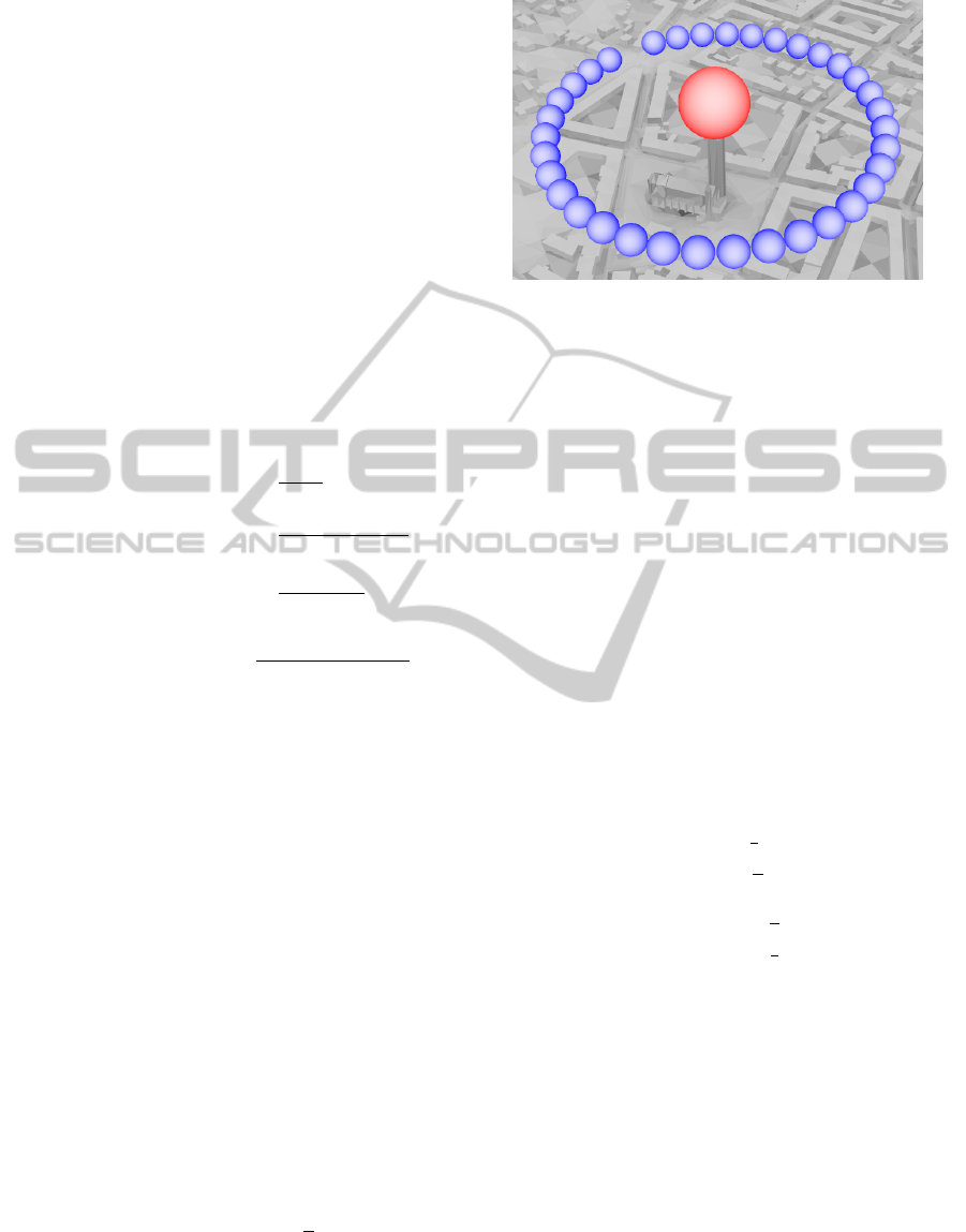
Figure 3: The identification of points-of-interest (POI) in a
scene is very important for its presentation: The red sphere
shows the actual POI and the blue spheres show a subse-
quence of a generated path around the POI, which the cam-
era will take.
This ensures, that the whole model is visible from
a top view and the view gets a good overview of the
scene.
4.3.2 Overview Path
After the start position has been determined, the
viewer should get an overview of the whole scene.
In this step, a circle, which is scaled in x direction
depending on the length and in y direction depend-
ing the width of the scene is constructed. The actual
scale factors in x and y are different depending on the
model type. The scale factors for object-types are de-
fined in Equation (9) and the scale factors for area-
types are defined in Equation (10).
factor
Ob j
=
l
2
+ w
w
2
+ l
!
(9)
factor
Area
=
w
2
l
2
!
(10)
where l corresponds to the length and w corresponds
to the width of the model.
4.3.3 POIs Path
Up to now, the viewer knows already what the scene
is about and hence it is time to show some highlights
of the model to him. In the preprocessing step, POIs
were computed. However, these points can not be
used immediately, because the path should not target
them directly, but e.g., fly around it. And exactly that
is done in the final path. Around each POI a scaled
circle is constructed, like it was in the overview step,
and this circle is then part of the path of the camera.
An example of such a POI path is shown in Figure 3.
AutomaticFly-throughCameraAnimationsfor3DArchitecturalRepositories
339

The individual POIs are then combined by finding
a point on the circle, where the distance to the current
camera position is minimal. Then the camera flies
around the POI by looking at it and then it is contin-
ued with the next POI.
5 VISUALIZATION
The control points for the path for the fly-through an-
imation are constructed with the algorithm described
in Section 4. Now these control points are used to
visualize a fly-through animation through the given
scene. Therefore, HTML/X3DOM is used. X3DOM
allows to define interpolators, which will do the job
of interpolating between the extracted control points.
Actually, two different interpolators are used to get a
good looking fly-through animation:
• PositionInterpolator
• RotationInterpolator
where the former is used to move the camera and the
latter is used to rotate the camera in such a way, that
the scene or the POI respectively can be seen. These
interpolators require to define keys and values. The
values of the interpolators are equal to the extracted
control points and the corresponding orientation re-
spectively. But the keys are defined between 0 and
1, where 0 corresponds to the start of the animation
and 1 corresponds to the end of it. The key values are
computed, such that longer distances between control
points will get a greater key interval and that shorter
distances will get a smaller key interval. This en-
sures, that the camera always moves approximately
with the same speed. However, with this configura-
tion the POIs are visited to fast. Hence, the distances
within a POI circle are weighted with a factor f to get
more coherent results.
6 CONCLUSIONS
The algorithm presented in this paper, can handle ar-
bitrary triangle soups, where no more sophisticated
properties like water-tightness or manifoldness must
be met. Hence, it is possible to give an arbitrary
model or scene to the algorithm and a good overview
of the model as well as points of interest, which rep-
resent the highlights of a scene, will be shown to the
viewer automatically.
Future work will be to add the possibility of fly-
ing into objects. Then a user gets also impressions of
the inside. While the necessary collision detection for
this could be done with 3D grid-based data structures,
the identification of relevant inner points and appro-
priate paths will be a challenge.
ACKNOWLEDGEMENTS
The authors gratefully acknowledge the generous sup-
port of the Austrian Research Promotion Agency
(FFG) for the research project GINGER (Graphi-
cal Energy-Efficiency-Visualization in Architecture),
grant number 840190 as well as the support of the
DURAARK project founded within “ICT-2011-4.3-
Digital Preservation”.
REFERENCES
Ahmed, A. and Eades, P. (2005). Automatic Camera Path
Generation for Graph Navigation in 3D. Proceedings
of the Asia-Pacific Symposium on Information Visual-
isation, 45:27–32.
Argelaguet, F. and Andujar, C. (2010). Automatic Speed
Graph Generation for Predefined Camera Paths. Smart
Graphics, 6133:115–126.
Berndt, R., Bl
¨
umel, I., and Wessel, R. (2010).
PROBADO3D – Towards an Automatic Multi-
media Indexing Workflow for Architectural 3D
Models. Proceedings of the International Conference
on Electronic Publishing, 14:79–88.
Christie, M., Langu
´
enou, E., and Granvilliers, L. (2002).
Modeling Camera Control with Constrained Hyper-
tubes. Proceedings of the International Conference on
Principles and Practice of Constraint Programming,
8:618–632.
Christie, M., Machap, R., Normand, J.-M., Olivier, P., and
Pickering, J. (2005). Virtual Camera Planning: a Sur-
vey. Proceedings of the International Conference on
Smart Graphics, 5:40–52.
Christie, M. and Olivier, P. (2009). Camera Control in
Computer Graphics: Models, Techniques and Appli-
cations. ACM Siggraph Asia Courses, 3:3:1–3:197.
Courty, N. and Marchand, E. (2001). Computer Animation:
a New Application for Image-Based Visual Servoing.
Robotics and Automation, 1:223–228.
dos Santos, S. R. and Duarte, P. M. (2011). Supporting
Search Navigation by Controlled Camera Animation.
Symposium on Virtual Reality, 13:207–216.
Drucker, S. M. and Zeltzer, D. (1994). Intelligent Camera
Control in a Virtual Environment. Graphics Interface,
15:190–199.
Durable Architectural Knowledge (2013). DURAARK.
http://duraark.eu/.
Espiau, B., Chaumette, F., and Rives, P. (1992). A New Ap-
proach to Visual Servoing in Robotics. IEEE Trans-
actions on Robotics and Automation, 8:313–326.
Hart, P. E., Nilsson, N. J., and Raphael, B. (1968). A Formal
Basis for the Heuristic Determination of Minimum
GRAPP2014-InternationalConferenceonComputerGraphicsTheoryandApplications
340

Cost Paths. IEEE Transactions on Systems Science
and Cybernetics, 4:100–107.
Jardillier, F. and Langu
´
enou, E. (1998). Screen-Space Con-
straints for Camera Movements: the Virtual Camera-
man. Computer Graphics Forum, 17:175–186.
Metadata for Architectural Contents in Europe (2006).
MACE. http://portal.mace-project.eu/.
Oliver, P., Halper, N., Pickering, J., and Luna, P. (1999). Vi-
sual Composition as Optimisation. AISB Symposium
on AI and Creativity in Entertainment and Visual Art,
1:22–30.
Salomon, B., Garber, M., Lin, M. C., and Manocha, D.
(2003). Interactive Navigation in Complex Environ-
ments using Path Planning. Proceedings of the Sym-
posium on Interactive 3D graphics, 5:41–50.
Shapeways (2013). Shapeways.
http://www.shapeways.com.
Sokolov, D. and Plemenos, D. (2005). Viewpoint quality
and scene understanding. Proceedings of the Interna-
tional Conference on Virtual Reality, Archaeology and
Intelligent Cultural Heritage, 6:67–73.
Sokolov, D., Plemenos, D., and Tamine, K. (2006). Meth-
ods and Data Structures for Virtual World Explo-
ration. The Visual Computer, 22:506–516.
Stoev, S. L. and Straßer, W. (2002). A case study on au-
tomatic camera placement and motion for visualizing
historical data. Proceedings of the Conference on Vi-
sualization, 13:545–548.
Trimble 3D Warehouse (2013). Trimble 3D Warehouse.
http://sketchup.google.com/3dwarehouse/.
Viola, I., Feixas, M., Sbert, M., and Groller, E. (2006).
Importance-Driven Focus of Attention. IEEE Trans-
actions on Visualization and Computer Graphics,
12:933–940.
AutomaticFly-throughCameraAnimationsfor3DArchitecturalRepositories
341
