
3D Head Model Fitting Evaluation Protocol on Synthetic Databases for
Acquisition System Comparison
Catherine Herold
1,2,3,4
, Vincent Despiegel
1,2
, St´ephane Gentric
1,2
,
S´everine Dubuisson
4
and Isabelle Bloch
1,3
1
Identity & Security Alliance (The Morpho and Telecom ParisTech Research Center), Paris, France
2
Morpho, Safran Group, 11 boulevard Galli´eni, Issy-les-Moulineaux, France
3
Institut Mines-Telecom, Telecom ParisTech, CNRS LTCI, Paris, France
4
ISIR, UPMC Sorbonne Universit´es, Paris, France
Keywords:
3D Face Reconstruction, Metrics, Evaluation Protocol, Comparison of Acquisition System Configurations.
Abstract:
Automatic face recognition has been integrated in many systems thanks to the improvement of face comparison
algorithms. One of the main applications using facial biometry is the identity authentication at border control,
which has already been adopted by a lot of airports. In order to proceed to a fast identity control, gates have
been developed, to extract the ID document information on the one hand, and to acquire the facial information
of the user on the other hand. The design of such gates, and in particular their camera configuration, has a high
impact on the output acquisitions and therefore on the quality of the extracted facial features. Since it is very
difficult to validate such gates by testing different configurations on real data in exactly the same conditions,
we propose a validation protocol based on simulated passages. This method relies on synthetic sequences,
which can be generated using any camera configuration with fixed parameters of identities and poses, and
can also integrate different lighting conditions. We detail this methodology and present results in terms of
geometrical error obtained with different camera configurations, illustrating the impact of the gate design on
the 3D head fitting accuracy, and hence on facial authentication performances.
1 INTRODUCTION
With the recent improvements of face recognition al-
gorithms, facial biometry now offers very high per-
formances in terms of recognition rate when acquisi-
tions are performed in good conditions. Thanks to
these advances, a lot of automatic face recognition
systems have emerged, implying different levels of
cooperation from the user. Among them, automatic
border control gates have already been validated and
deployed in several airports. Nevertheless, the main
systems evaluated until now require the passengers
to position themselves in front of a captor in order
to acquire a frontal view, which is constraining from
the user point of view. A new challenge today is to
provide a simpler system for users, while ensuring
high biometric performances. In case of such uncon-
strained scenarios, an important criterion impacting
the face recognition quality is the pose of the face in
the images (frontal or not), besides other factors such
as the resolution or the illumination conditions.
In this paper, we consider on-the-fly systems
which do not require any specific behavior of users
with respect to the cameras. To optimize the system
performances, it is therefore necessary to carefully
position the sensors in order to deal as well as pos-
sible with the various poses of faces in the system. As
3D face fitting is an important step for face recogni-
tion against the frontal image of a passport, we com-
pare different acquisition systems in terms of camera
number and positions by their 3D fitting accuracy. We
propose therefore a complete methodology to validate
the 3D head model estimated from the corresponding
acquisitions using geometricevaluation. Further stud-
ies on biometric evaluation and impact of ageing and
expression are not part of this paper.
A crucial point when comparing different systems
with respect to a given parameter is to fix all the re-
maining ones. However, when proceeding to real ac-
quisitions, it is impossible to reproduce exactly the
same illumination conditions and to ask users to have
296
Herold C., Despiegel V., Gentric ., Dubuisson S. and Bloch I..
3D Head Model Fitting Evaluation Protocol on Synthetic Databases for Acquisition System Comparison.
DOI: 10.5220/0004670502960305
In Proceedings of the 9th International Conference on Computer Vision Theory and Applications (VISAPP-2014), pages 296-305
ISBN: 978-989-758-009-3
Copyright
c
2014 SCITEPRESS (Science and Technology Publications, Lda.)
identical behaviors and face positions. To completely
control the parameters which should be stable when
evaluating the camera configuration, we propose to
do the evaluation on synthetic data in order to fix all
other acquisition parameters (identity, pose, illumina-
tion). Hence, no noise is introduced by variations be-
tween different not studied parameters.
We first present our global face recognition work-
flow, and detail the 3D model we use in Section 2. In
Section 3, we propose a methodology to evaluate dif-
ferent acquisition systems for face recognition gates
without any real acquisition. This includes a synthetic
database generation step and the metrics characteriz-
ing the quality of a configuration on these simulated
sequences. We briefly present two algorithms we use
for the evaluation in Section 4. The corresponding re-
sults with our methodology are detailed in Section 5,
and show the impact of the gate design on the 3D head
fitting quality.
2 CONTEXT
2.1 Face Recognition Workflow
Face recognition systems can be based on different
types of sensors, such as range scanners, infrared or
visible cameras. As visible range cameras are the
most commonly used, we limit our study to acquisi-
tion systems based on these last sensors. Thus, the in-
put of the face recognition algorithms is a set of video
sequences, and the final output is a binary decision
corresponding to the face authentication result.
The different steps of the algorithm are as follows.
While the person walks in the gate, a first step of
face and fiducial point detection is performed on each
available view. After the initialization step, tracking
and/or detections are performed in the next frames, to
obtain the features needed in each frame to estimate
the specificities of the face seen in the videos. As the
pose is unconstrained in gate scenarios, this is done
using a 3D model which offers robustness to pose
variations (Blanz et al., 2005). This model is fitted to
the observations, to extract the specificities of the per-
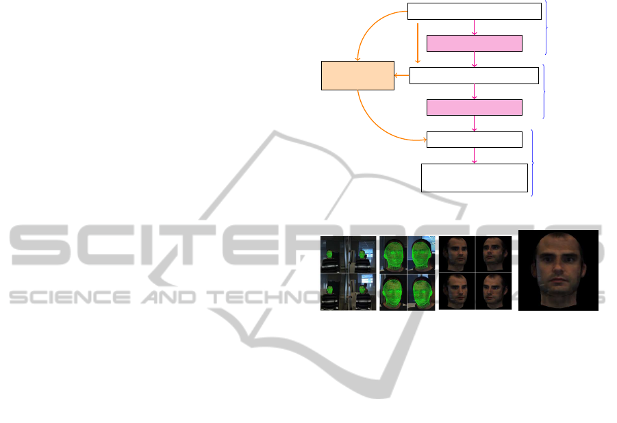
son to authenticate. As illustrated in Figure 1(a), this
fitting can be performedin a recursiveway, by making
a first estimation at the beginning, and then updating
the model with the new observations, or globally, by
using all observations together. Once the model has
been fitted to the observations (Figure 1(b)), a frontal
view can be generated (Figure 1(c)) to proceed to the
face comparison. For our study, we focus specifically
on the quality of the model fitting (Figure 1(b)). In
the next part, we briefly present this shape model and
the associated parameters to be estimated.
Face and feature point detection
Model fitting
frame 1
Initialization
Head detection and/or tracking
Global
model fitting
Model improvement
Frontal view synthesis
2
to N
Face comparison with
the reference picture
End of sequence
Authentication
(a) Acquisition and authentication workflow. In orange: specific steps for an global approach.
In magenta: recursive approach.
(b) Model fitting on the observations (c) Frontal view
Figure 1: Global workflow: from detection to authentica-
tion.
2.2 3D Head Reconstruction
Among the different face models which have been
proposed in the past, we choose a 3D deformable
shape model constructed in a similar way as the 3D
Morphable Model (3DMM) introduced in (Blanz and
Vetter, 1999). As the final aim is to establish a com-
parison score between the frontal view of the esti-
mated face and its corresponding ID picture, it is nec-
essary to adapt the model such that it fits as well as
possible the observed identity. The 3DMM describes
the face space on the two following aspects:
• The shape space, characterized by a mean shape
¯
S
and a set of eigenvectors
s
i
,i = 1,...,M
com-
puted by principal component analysis over a
database of aligned head scans. These vectors cor-
respond to deformations describing shape varia-
tions in the face class. Each instance of this model
can then be written as:
S = κ(
¯
S+
M
∑
i=1
α
i
s
i
), (1)
where α
i
are the weighting parameters which
characterize the similarity with the mean shape
and κ is a scaling factor. The mean shape
¯
S is
defined by a set of n
v
3D vertices, and each vec-
tor s
i
correspondsto deformations associated with
3DHeadModelFittingEvaluationProtocolonSyntheticDatabasesforAcquisitionSystemComparison
297
this set of points. An equivalent equation can be
written for a vertex v, as s
v
= κ( ¯s
v
+
∑
M
i=1
α
i
s
i
v
),
where s
v
and ¯s
v
are positions and s
i
v
a deformation
relative to the vertex v. A mesh is then defined
from these vertices, by adding facets definition to
describe the entire head surface.
• The texture, that associates a color with each ver-
tex of the mesh.
The shape and the texture of each instance can be
adapted in order to fit to the observations.
In this article, we will only evaluate the quality of
the estimation for the geometrical part of the model,
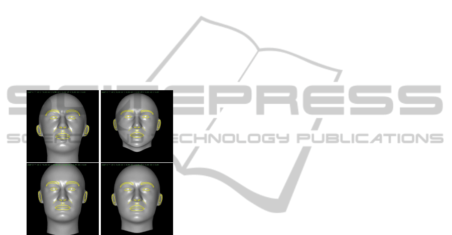
given various system configurations. Some instances
of the morphable shape model are given in Figure 2,
illustrating its variations depending on the different
sets of parameter values {α
i
,i = 1,...,M}.
Figure 2: Some instances of the deformable shape model
(all faces are generated at the same pose and scale, and with
identical lighting conditions). The global shape changes for
each instance, and more specifically the nose shape, the ear
orientation or the chin.
The first algorithms to estimate the shape and tex-
ture parameters of the 3DMM used stochastic gradi-
ent descent (Blanz and Vetter, 1999) or Levenberg-
Marquardtoptimization (RomdhaniandVetter, 2005)
on a single image only. Nevertheless, the informa-
tion is not complete when only single images are used
to perform the fitting, especially in the case of low-
resolution images. Moreover, due to the projection
from the 3D world into the image plane and the oc-
clusions of some parts of a face in an image, some
information is missing and the estimation might be
erroneous. This is why new algorithms based on mul-
tiple image fitting have been proposed to take multi-
views or video sequences into account, thus increas-
ing the estimation accuracy. In (Amberg et al., 2007),
the fitting algorithm proposed in (Romdhani and Vet-
ter, 2005) was adapted to a set of images acquired
simultaneously, which improves the results of algo-
rithms using only a single image. In (Van Rootseler
et al., 2011), two experiments were proposed to ex-
ploit video sequences: the first one consists in esti-
mating independently the parameters at each instant
before linearly combining these estimations. The sec-
ond one uses all the input images together to opti-
mize the parameters, leading to a single estimation
based on the whole sequence. The offline method we
chose in this paper is close to the latter, as it estimates
the set of shape parameters using all images together.
Besides, we also use the recursive method proposed
in (Herold et al., 2012) and based on a particle fil-
ter. Thus, temporal constraints can also be used to im-
prove the pose and shape fitting. These two methods
are summarized in Section 4 and used for our evalua-
tion.
3 DATABASE GENERATION AND
QUALITY MEASURES
3.1 Methodology
The validation of real systems raises several issues.
First, wide acquisition campaigns have to be per-
formed to collect video sequences with different per-
sons. Moreover, to compare the different acquisition
systems, any parameter that could impact the perfor-
mances should be fixed, in order to evaluate prop-
erly each system’s characteristics. Unless the differ-
ent systems are acquiring simultaneously sequences
of users passing through the gate, there is no way
to reproduce exactly the same trajectory of a person,
thus making the comparison on identical inputs im-
possible. Finally, each of the systems has to be mate-
rially conceived, which is costly and time consuming.
We propose a methodology based on evaluations over
different sets of synthetic databases to evaluate the ac-
curacy of pose and shape estimation algorithms with
respect to different gate configurations, thus provid-
ing a way of comparing different system configura-
tions.
In the remainder of this section, we describe the
type of video sequences which have been generated
to proceed to the evaluation. The process of synthetic
sequence generation is summarized in Figure 3.
3.2 Identities
Each identity definition is composed of shape and tex-
ture information. The generation of synthetic views is
possible using these two aspects together.
VISAPP2014-InternationalConferenceonComputerVisionTheoryandApplications
298
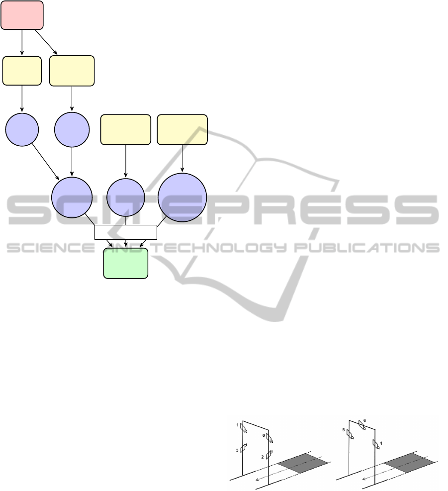
Real
faces
3D face
scans
Set of 2D
images
Shape
Texture
Real
sequences
Acquisition
system
Identities
Set of
poses
Calibration
Synthetic
images
Model
fitting
Model
fitting
PovRay
Figure 3: Synthetic sequences generation.
Shape. 40 man and 35 woman real head scans have
been acquired to obtain a raw 3D representation of
each face. A 3D fitting procedure has then been ap-
plied to represent these shapes with the same mesh
structure as the model introduced in Section 2.2.
Thus, we obtain the 3D position of each vertex of the
model for the given scan. This step is necessary to
compare the estimated face to the real one. The shape
of each synthetic face S
j
id
is then created by a combi-
nation of four 3D real head scans chosen from those
available:
S
j
id
=
4
∑
i=1
c
j
i
S
σ(i, j)
, (2)
with the constraints 0 ≤ c
j
i
≤ 1 and
∑
4
i=1
c
j
i
=
1. {σ(i, j),i ∈ {1, ..., 4}} defines which shapes have
been used to generate the resulting one. The parame-
ters c
j
i
have been sampled randomly, the proportions
of the corresponding shapes S
σ(i, j)
are therefore all
different. Synthetic faces of men and women have
been created with the corresponding real scans to re-
spect the morphology differences.
Texture. The texture associated with the shape
gives a colordefinition for each facet of the model. To
obtain the texture for each ID, the following process
is applied. Our model is fitted on images of a real face
seen under various poses to extract the visible part of
the texture in each of them. The extracted textures are
then merged together to obtain the complete texture.
For each synthetic ID, images of a different person
have been used to diversify the generated textures.
Both shape and texture components of faces gen-
erated in this way come from real faces and character-
ize therefore realistic identities. A total of 47 identi-
ties (36 men and 11 women) has been created follow-
ing this process. We consider here that the combina-
tion of independent shape and texture does not alter
the validity of the resulting faces. Nevertheless, other
acquisition systems generating simultaneously depth
maps and corresponding 2D color images could be
used to recreate synthesized sequences corresponding
entirely to real faces (with the Microsoft Kinect
TM
for
instance).
3.3 Associated Sequences
Once the identities are defined, we have to specify
scenarios to generate synthetic sequences of people
walking through a gate. To this aim, we have to simu-
late an acquisition system and its possible configura-
tions. In our experiments, we used the configurations
illustrated in Figure 4. One of them is equivalent to
a real system we have already built in our laboratory,
the others are simulated variants which have not been
constructed yet. For the first one, four cameras are
considered,two on each side of the outdoorframe; the
second one has only one camera on each side, in ad-
dition to one camera above the door. All cameras are
pointing towards the center of the gate, located about
two meters in front of the door. The following config-
Figure 4: Configuration of the acquisition system in the 4
and 3-cameras gate.
urations are considered, by using some or all cameras
of one of the systems (numbers refer to Figure 4):
• 2A: 2 cameras aligned vertically (0,2)
• 2B: 2 cameras aligned horizontally (0,1)
• 2C: 2 crossed cameras (0,3)
• 3A, 3B, 3C: 3 cameras (0,1,3), (1,2,3) and (4,5,6)
• 4A: 4 cameras (0,1,2,3)
3DHeadModelFittingEvaluationProtocolonSyntheticDatabasesforAcquisitionSystemComparison
299
Additionally to the extrinsic parameters of each
camera, the impact of the image resolution can also
be evaluated by generating images of different sizes.
Indeed, the face and feature point detection quality
depends on the resolution of the face, and this param-
eter should then be taken into account when evaluat-
ing an acquisition system. For further studies, light-
ing systems can also be added in the scene definition
to evaluate their impact.
Finally, a pose has to be defined for each times-
tamp of the sequence. We define this set of poses
given the real poses of heads observed in sequences
acquired with persons using our real 4-camera sys-
tem. Thus, we describe usual trajectories done by
users in real systems. The poses defined in this way
characterize the move of a person walking regularly
from the entrance of the gate to the limit of the visi-
ble area by the cameras. Ten poses cover this move,
which correspond to camera acquisitions at 5 − 8
frames per second for a medium speed walk.
Figure 5 gives some examples of images which
have been generated for different poses and identities.
The software POV-Ray (PovRay, 2012) has been used
to generate these sequences. The lighting or the image
resolution can easily be modified to generate other se-
quences in order to evaluate the various parameters of
the acquisition system outline above. The use of real
data to generate the sequences in terms of faces, cam-
eras and trajectories ensures that the generated syn-
thetic data are close to the real ones.
Figure 5: Examples of synthetic images generated from a
4-cameras configuration.
3.4 Quality Measures
Different metrics have been proposed to evaluate the
quality of a shape fitting or reconstruction(Park et al.,
2002), and their significance depends on the purpose
of this estimation. In our case, with the aim of com-
paring face information with an ID picture, we per-
form the evaluation via geometrical measures com-
puted over a subset of vertices corresponding to the
frontal part of the face V
f
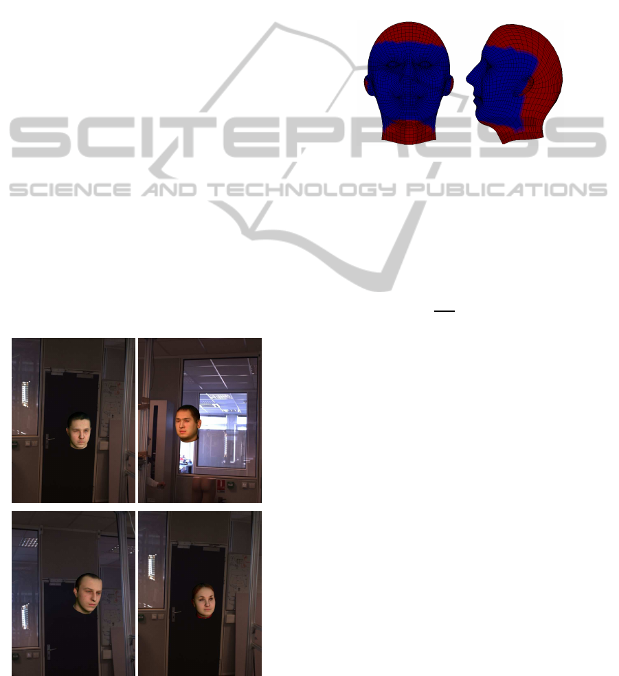
, as shown in Figure 6. First,
Figure 6: In blue: V
f
, which represents the set of vertices
selected to compute the mean error between a 3D head scan
and the estimation of the same face in the video. The red
vertices are not taken into account, as they are not used to
compare the faces in the biometric step afterwards, and are
not fitted to the observations.
the following 3D point-to-point error can be com-
puted in the gate coordinate system G:
Err
3D
=
1
N
V
f
N
V
f
∑
v=1
ks
s
v
− s
e
v
k
2
, (3)
where k···k
2
is the Euclidean norm, N
V
f
is the num-
ber of vertices belonging to V
f
, and s
s
v
is the true posi-
tion of the v
th
vertex of the head scan in G computed
as:
s
s
v
= R
GT
s
s
v,0
+ T
GT
, (4)
where s
s
v,0
is the same vertex of the scan at frontal
pose, R
GT
the rotation and T
GT
the translation
used to generate the images. The position s
e
v
is
given by the estimated pose (R
e
,T
e
) and shape
(κ
e
,{α
e
i
,i = 1, ..., M}) as follows:
s
e
v
= κ
e
R
e
( ¯s
v
+
M
∑
i=1
α
i
s
i
v
) + T
e
. (5)
It is necessary to take the shape and the pose estima-
tion together into account to estimate the fitting qual-
ity. Indeed, as they are estimated jointly, several so-
lutions of joint pose and shape can verify good head
fitting on the observations, this is why we compare
the solution on the vertex positions computed in G.
This measure, illustrated in Figure 7, is the closest to
the error which is minimized in the shape and pose
fitting procedure. It characterizes how close are the
VISAPP2014-InternationalConferenceonComputerVisionTheoryandApplications
300

x
y
s
GT
0
•
s
e
0
•
Err
3D
(a) Front view
Err
3D
s
e
0
•
s
GT
0
•
s
GT
0
/∈ mesh(S
e
)
S
e
Err
3D
s
e
0
•
s
GT
0
•
s
GT
0
∈ mesh(S
e
)
S
e
z
(b) Side view
Figure 7: Error Err
3D
for vertex s
0
calculated from the real
shape and the estimated one.
estimated vertices to their real positions in the gate
coordinate system.
Other measures can also be computed, such as
the following point-to-surface error, which compares
more specifically the shape estimation to the ground
truth shape:
Err
CP
3D
=
1
N
V
f
N
V
f
∑
v=1
d(s
s
v
,S
e
), (6)
where d characterizes the distance between a ground
truth vertex s
s
v
and the closest point of the surface de-
scribed by the estimated mesh S
e
. This allows local
misalignment (which can happen due to missing tex-
tures in some face areas) as long as the surfaces are
close to each other (Figure 8).
Finally, for comparison of 2D frontal views, the
following 2D point-to-point error can also be used:
Err
2D
=
1
N
V
f
N
V
f
∑
v=1
s
s
f,v
.xy− s
e
f,v
.xy
2
, (7)
where X.xy corresponds to the 2-dimensional vec-
tor composed of the x and y coordinates, which are
the image coordinates when making the orthographic
projection. s
s
f,v
is the vertex position in the frontal
s
GT
0
•
s
e
0
•
×
Err
CP
3D
×
×
×
x
y
(a) Front view
z
Err
CP
3D
s
e
0
s
GT
0
•
•
s
GT
0
/∈ mesh(S
e
)
S
e
Err
CP
3D
= 0
s
e
0
s
GT
0
•
•
s
GT
0
∈ mesh(S
e
)
S
e
(b) Side view
Figure 8: Error Err
CP
3D
for vertex s
0
calculated from the real
shape and the estimated one.
head scan, and the estimated vertices are computed
as:
s
e
f,v
= R
−1
GT
(s
e
v
− T
GT
). (8)
4 FACE RECONSTRUCTION
ALGORITHMS
The proposed evaluation protocol can be tested with
any algorithm which estimates the pose and the shape
in video sequences. Similar conclusions can be drawn
concerningthe different gate configurationswhich are
evaluated, whatever the tested method. This is il-
lustrated in this paper by providing results obtained
with one method performing the estimation globally
over the whole sequence and one sequential method.
Both of them take as input the images and a set of
facial fiducial points which have been automatically
detected. This information is called observations and
denoted generically y
t
at time t. The output is the 3D
shape estimation (the scale parameter κ and the shape
deformation parameters {α
i
,i = 1,...,M}), which is
denoted by θ, and pose estimation at each instant
{T
1
,R
1
,...,T
T
,R
T
}. The pose and the shape estima-
tions must be handled together, as both parameters
3DHeadModelFittingEvaluationProtocolonSyntheticDatabasesforAcquisitionSystemComparison
301

impact the observations, and as different combina-
tions of (shape, pose) can explain the sparse set of ob-
servations used for the fitting. We detail here shortly
the two standard methods used to evaluate the pose
and shape from video sequences.
4.1 Levenberg-Marquardt
Optimization
The Levenberg-Marquardt (LM) (Marquardt, 1963)
method iteratively minimizes an energy E combin-
ing gradient descent and Gauss-Newton algorithms.
In our case, we applied it in an offline manner (Fig-
ure 1(a)), estimating jointly the poses for all frames
and the shape parameters (the same for the whole se-
quence) given the video.
This algorithm starts from an initial guess u
0
=
T
0
1
,R
0
1
,...,T
0
T
,R
0
T
,θ
0
of all unknownvalues to be es-
timated. The 3D pose R
0
t
,T
0
t
of the face at each time
t is estimated given a set of 3D points reconstructed
from the correspondingdetections in the different im-
ages acquired at this instant using the calibration pa-
rameters. Following the method in (Umeyama, 1991),
the pose parameters are adapted by fitting the mean
model to these points. The initial shape deformation
parameters are set to zero, which corresponds to the
mean model used for the pose fitting. Given the func-
tion which associates the state u to the corresponding
observations, an error can be computed between the
real observationsand the ones generated from u. Con-
sidering only the feature point criterion, the aim of the
algorithm is to minimize the associated energy: E =
∑
T
t=1
1
D(t)
∑
D(t)
p=1
||m(p,t,u) − o(p,t)||
2
2
, where D(t) is
the number of detected feature points at time t, o(p,t)
their 2D positions and m(p,t,u) the projection of the
corresponding points from the model on the images
given the current pose and shape estimations. We aim
at minimizing this error, by applying recursively cor-
rection steps to u, given the current error and the Ja-
cobian of the function f.
This method uses all frames together to proceed to
the optimization. Thus, a single value θ is estimated,
common to all frames. Indeed, as the shape parame-
ters characterize the identity, these are supposed to be
constant (assuming that the person does not change
its facial expression).
4.2 Particle Filter Optimization
The particle filter (PF) method used to evaluate the
pose and shape throughout a sequence is inspired
from (Herold et al., 2012). The idea of this algorithm
is to integrate the shape parameters θ to be estimated
in the particle state, and to update the density p(θ)
with each new observation. The particle weights are
computed by comparing the projection of the land-
marks given the particle state (a pose and a set of pa-
rameters) to the ones detected in the images. This
method is applied recursively (Figure 1(a)), meaning
that the shape estimation is updated at each instant
given the new observations.
At each time t, the following procedure is applied
given the set of N particles and the new observations
y
t
:
• for each particle i: (i) move the static shape pa-
rameters to obtain a new hypothesis θ
(i)
t
; (ii) esti-
mate the pose R
(i)
t
,T
(i)
t
given a subset of the fea-
ture point detections and the particle shape param-
eters θ
(i)
t
; (iii) update its weight by computing the
likelihood of the state with the observations;
• compute the current output state (R
t
,T
t
,θ
t
). This
is done by choosing the particle with the highest
weight, or by computing the weighted mean over
the set of particles.
Unlike the LM method, only the observations until
time t are used when computing the evaluation at this
instant. As only few features are used in each view
to evaluate the pose and the shape of the face, this
method allows us to maintain different shape param-
eters hypotheses and to validate them when new dis-
criminant observations are available.
5 EVALUATION
In this section, we apply the proposed methodology
to evaluate the head model fitting quality depending
on the number and the positions of the cameras used
to acquire the images in the gate. This evaluation is
done considering the results obtained on the synthetic
sequences with the two fitting algorithms presented
in Section 4. The LM implementation is based on the
levmar library available online (Lourakis, 2004). We
do not use the known feature point positions as inputs
for the two fitting algorithms. Instead, we launch the
feature point detectors used for real sequences, in or-
der to have the same noise and eventual bad or miss-
ing detections associated to these detectors.
Errors presented below are not given in pixels but
in percentage of the distance between the two eyes
to have an absolute measure. Figure 9 illustrates
the error distribution for a subset of sequences of
the database using some of the configurations listed
above. The PF method has been used to generate
these results, which are given as a percentage of the
VISAPP2014-InternationalConferenceonComputerVisionTheoryandApplications
302
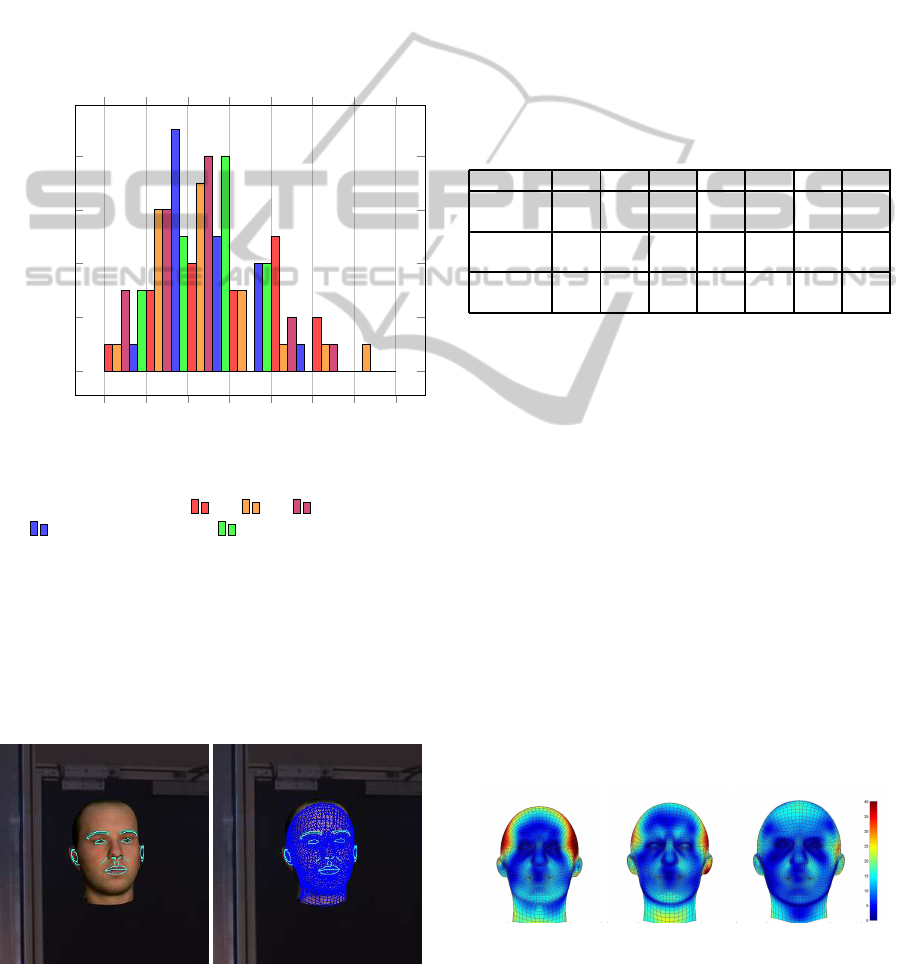
inter-eyedistance (ied). We can see that in most cases,
using 4 cameras (green bars) outperforms all other
configurations, as no sequence has an error above
11% of the ied. The 3-cameras configuration (blue
bars) comes after, with almost all errors below 11%
of the ied. Finally, with only 2 cameras, some errors
reach 14% of the ied. The errors are however smaller
with the 2C configuration (in purple) where more
points can be seen thanks to the viewpoint change.
Figure 10 illustrates how well the estimated model is
consistent with the observations. Only a small set of
feature points related to the edges plotted on the left
are used to evaluate the pose and shape parameters.
8 9 10 11 12 13 14
0
2
4
6
8
Error (% of the inter-eye distance)
Number of sequences
Figure 9: Error (Err
3D
) variations (in % of the inter-eye
distance) with different camera configurations for some se-
quences: two cameras (2A
, 2B , 2C ), three cameras
(3B
) and four cameras (4A ).
Table 1 shows the mean errors computed over all
the sequences of the database with respect to the cam-
era configurations with the PF and the LM methods.
We can see that the error and the number of cameras
are correlated. The general trend is that the fitting
is improved when more views are used. Neverthe-
Figure 10: Example of edge and mesh fitting with the par-
ticle filter method (zoom on the face area). The inter-eye
distance on the input image is 36 pixels.
less, for a given number of cameras, their positions
can also impact the quality, as shown for instance
for 2A (vertical alignment) and 2C (crossed cameras).
The improvement with the PF method is due to the
sampled subset of feature points which leads to more
robustness to the outliers. The stability of this sam-
pling based method has been verified by running it
five times for the whole set of sequences. The stan-
dard deviation of the means of Err
3D
computed on
configuration 2A (resp. 4A) is 0.12% (resp. 0.05%)
of the inter-eye distance, which is small relatively to
the highest error variations observed between the dif-
ferent configurations.
Table 1: Mean errors with the PF and the LM methods given
different camera configurations. For the PF method, the
mean is computed over 5 runs. Errors are given as a per-
centage of the inter-eye distance.
System 2A 2B 2C 3A 3B 3C 4A
LM Err
3D
23.3 22.8 22.9 22.7 22.9 26.2 22.2
PF Err
3D
12.2 11.8 11.0 10.8 10.5 10.4 10.5
LM Err
CP
3D
16.7 16.0 16.1 16.0 16.2 18.5 15.4
PF Err
CP
3D
6.6 5.8 5.6 4.6 4.5 5.0 4.7
LM Err
2D
9.2 9.5 8.1 7.9 8.3 8.9 7.6
PF Err
2D
8.4 8.2 8.2 7.6 7.2 6.5 6.9
The error magnitude in this table should be corre-
lated with the resolution of the images (600 × 800),
the distance of the person to the sensors (between
1.5 and 2 meters), and the sparse distribution of the
features used for the fitting. Nevertheless, the rela-
tive gain between the worst and the best configuration
reaches 14.7% (resp. 4.7%) for the PF method (resp.
LM method) considering the error Err
3D
.
Figure 11 illustrates the error repartition over the
face for three faces of our database, using the 4-
cameras configuration. The 3D errors are not dis-
tributed uniformly over the mesh, because we only
use a few fiducial points to perform the fitting. In-
deed, in some areas of the mesh such as on the neck,
above the ear or on the cheeks, there are therefore no
clues to guarantee the fitting. This explains the higher
errors in these areas, in comparison with the eyes ar-
eas, where the error is less than 10% of the inter-eye
distance.
Figure 11: 3D error (Err
3D
) distribution over the face for
three faces of the synthetic database. The particle filter
method with 4-cameras has been used to estimate the shape.
Errors are given as a percentage of the inter-eye distance.
3DHeadModelFittingEvaluationProtocolonSyntheticDatabasesforAcquisitionSystemComparison
303

Influence of the shape and texture on the accuracy.
We now verify the influence of texture or shape on
the pose and shape estimation quality. To this end, we
used two new sets of synthetic data:
• base B
shape
: ten sequences, changing only the
shape from one sequence to another one, all other
parameters remaining fixed;
• base B
tex
: ten sequences, changing only the tex-
ture from one sequence to another one.
We evaluated the pose and shape estimation using the
Levenberg-Marquardt algorithm. The accuracy vari-
ation for each of these bases is given in Table 2. We
report only the 2D errors (Err
2D
) using the 3-cameras
configuration 3A.
Table 2: Error variations depending on shape or texture
variations only. The Levenberg-Marquardt optimization has
been used on configuration 3A.
Variation Mean Sigma Min Max
Shape (B
shape
) 7.65 1.8 5.72 11.87
Texture (B
tex
) 7.57 0.45 7.03 8.46
The results are significantly more stable with the
base B
tex
than with the base B
shape
. This can be ex-
plained by the fact that texture variations slightly al-
ter the detector quality at fixed pose and shape. For
instance, the appearance of an eye corner does not
change considerably for different facial textures. The
detected points are therefore almost the same for all
sequences of B
tex
, leading to very similar estimations.
For the base B
shape
, the texture and the poses are
fixed for all sequences, so we can assume that the
quality of the detections is equivalent for all of them.
Nevertheless, the errors obtained for this base are
more varied than for B
tex
, which is due to the shape
variability in the sequences. Indeed, some real shapes
cannot be generated because of the model constraints.
Some faces will therefore be easy to represent and
lead to low errors, but for others, it will not be possi-
ble to fit correctly the model to the data. This explains
why it is important to use real head scans when gen-
erating the synthetic sequences, in order to reproduce
this problem when evaluating the pose and estimation
algorithms.
6 CONCLUSIONS AND FUTURE
WORK
We have presented a complete workflow to evalu-
ate configurations of face recognition gates in terms
of 3D fitting quality. The methodology we propose
is based on synthetic data, which can be generated
with any number and configuration of cameras, light-
ing condition and resolution, while maintaining other
conditions fixed (identities, face poses). This allows
us to test an unlimited number of alternatives, with-
out bias introduced by people behavior and trajectory
variations, or constraints related to real campaign ac-
quisitions and material conception. The evaluation is
based on the accuracy measure of the 3D head fitting,
which is easily computable as we benefit from the
groundtruth used to generate the sequences. The gen-
eral trend shows that increasing the number of cam-
eras improves the accuracy of the estimation. More-
over, for a fixed number of cameras, their position
also impacts the accuracy: diversifying the points of
view increases the estimation quality (two crossed
cameras are better than two vertical cameras...). This
factor can be optimized with simulations, thus limit-
ing the number of real systems to build when making
the real data evaluation (for instance, evaluation of
the configuration 3C is not available with the initial
4-cameras system). In the future, such studies could
be extended to other factors, such as lighting and ex-
pression.
We limited our evaluation to geometrical results
on synthetic data. Another extension to this work
would be to develop the following aspects. First, it
would be interesting to compute geometrical mea-
sures on real data. The difficulty of this point is to
get the real position of each face vertex during a se-
quence. Additional depth sensors should be used to
this aim, or, at least, the ground truth of the face
should be known (using a 3D scanner for instance).
Besides, the relation between biometric performances
and errors on the estimation (3D pose and shape)
should be deepened, with respect to different face
comparison algorithms.
REFERENCES
Amberg, B., Blake, A., Fitzgibbon, A., Romdhani, S., and
Vetter, T. (2007). Reconstructing High Quality Face-
Surfaces using Model-Based Stereo. In International
Conference on Computer Vision, pages 1–8.
Blanz, V., Grother, P., Phillips, P., and Vetter, T. (2005).
Face Recognition Based on Frontal Views Generated
from Non-Frontal Images. In Conference on Com-
puter Vision and Pattern Recognition, pages 454–461.
Blanz, V. and Vetter, T. (1999). A Morphable Model for the
Synthesis of 3D Faces. In SIGGRAPH, pages 187–
194.
Herold, C., Despiegel, V., Gentric, S., Dubuisson, S., and
Bloch, I. (2012). Head Shape Estimation using a Par-
ticle Filter including Unknown Static Parameters. In
International Conference on Computer Vision Theory
and Applications, pages 284–293.
VISAPP2014-InternationalConferenceonComputerVisionTheoryandApplications
304

Lourakis, M. (2004). levmar: Levenberg-Marquardt
Nonlinear Least Squares Algorithms in C/C++.
http://www.ics.forth.gr/ lourakis/levmar/.
Marquardt, D. (1963). An Algorithm for Least-Squares
Estimation of Nonlinear Parameters. Journal of
the Society for Industrial and Applied Mathematics,
11(2):431–441.
Park, I. K., Lee, K. M., and Lee, S. U. (2002). Efficient
Measurement of Shape Dissimilarity between 3D
Models Using Z-Buffer and Surface Roving Method.
EURASIP, 2002(10):1127–1134.
PovRay (2012). Persistence of Vision Raytracer (version
3.6). http://www.povray.org/download/.
Romdhani, S. and Vetter, T. (2005). Estimating 3D Shape
and Texture using Pixel Intensity, Edges, Specular
Highlights, Texture Constraints and a Prior. In Con-
ference on Computer Vision and Pattern Recognition,
pages 986–993.
Umeyama, S. (1991). Least-Squares Estimation of Trans-
formation Parameters Between Two Point Patterns.
IEEE Transactions on Pattern Analysis and Machine
Intelligence, 13(4):376–380.
Van Rootseler, R. T. A., Spreeuwers, L. J., and Veldhuis, R.
N. J. (2011). Application of 3D Morphable Models
to Faces in Video Images. In Symp. on Information
Theory in the Benelux, pages 34–41.
3DHeadModelFittingEvaluationProtocolonSyntheticDatabasesforAcquisitionSystemComparison
305
