
3D Reconstruction with Mirrors and RGB-D Cameras
Abdullah Akay and Yusuf Sinan Akgul
GIT Vision Lab, Department of Computer Engineering,Gebze Institute of Technology, 41400, Kocaeli, Turkey
Keywords: Virtual Cameras, RGB-D Cameras, Kinect, 3D Reconstruction, Multi-view Geometry, Mirrors.
Abstract: RGB-D cameras such as Microsoft's Kinect have found many application areas in robotics, 3D modelling
and indoor vision due to their low-costs and ease of use. 3D reconstruction with RGB-
D cameras is relatively more convenient because they provide RGB and depth data simultaneously for each
image element. However, for a full 3D reconstruction of a scene, a single fixed RGB-D camera is
inadequate and using multiple cameras brings many challenges with them, such as bandwidth limitations
and synchronization. To overcome these difficulties, we propose a solution that employs mirrors to
introduce virtual RGB-D cameras into the system. The proposed system does not have any space
limitations, data bandwidth constraints, synchronization problems and it is cheaper because we do not
require extra cameras. We develop formulations for the simultaneous calibration of real and virtual RGB
and RGB-D cameras and we also provide methods for 3D reconstruction from these cameras. We conduct
several experiments to assess our system; numerical and visual results are found satisfying.
1 INTRODUCTION
RGB-D cameras such as Microsoft's Kinect sensor
have recently found many application areas in
robotics, 3D modelling and indoor vision due to
their low costs and ease of use. Specifically, these
cameras make the 3D reconstruction of objects more
convenient because they provide RGB and depth
data for each image element simultaneously without
any further process. As RGB-D cameras became
more reachable, many studies started to appear
(Smisek et al., 2013; Henry et al., 2012;
Khoshelham et al., 2012) that reconstruct 3D models
to be used by ordinary users. Public software
libraries (Izadi et al., 2011; Rusu et al., 2011) are
now offered to build custom 3D reconstruction
software from RGB-D data.
In spite of their convenience, for some cases, a
single view of an RGB-D camera is not sufficient to
capture the whole 3D scene at the same time for a
full reconstruction (Izadi et al., 2011; Henry et al.,
2012; Canessa et al., 2013; Oliver et al., 2012). With
a single depth map from a fixed RGB-D camera,
only visible surfaces can be reconstructed which is
inadequate for many applications. One can utilize
multiple RGB-D cameras to capture the scene from
several viewing locations so that almost all scene
surfaces are visible to RGB-D cameras, hence a full
3D reconstruction is possible (Henry et al., 2012;
Canessa et al., 2013; Oliver et al., 2012; Lai et al.,
2011).
However, using a system containing multiple
RGB-D cameras may not be practical due to several
problems. First, obviously, additional RGB-D
cameras in a 3D reconstruction system will increase
the total cost which makes the system less affordable.
Second, simultaneous communication with
multiple RGB-D cameras has communication
channel bandwidth problems. Therefore, customized
hardware is required to capture data from multiple
RGB-D cameras simultaneously which is both
expensive and requires expert knowledge (Hossny et
al., 2012). For example, communicating with more
than one Kinect, which is the most popular RGB-D
camera among ordinary users, cannot be done on a
standard personal computer or laptop on a single
USB bus without additional peripherals (Sumar et
al., 2011). This is because Kinect contains two
separate cameras (RGB and depth cameras) which
take all of the available USB bandwidth. Neither
USB 2.0 nor 3.0 controllers are capable of
supporting more than a single Kinect on a single bus
(Sumar et al., 2011). This is a serious limitation that
prevents employment of multiple Kinects on a
standard personal computer. There are additional
challenges for multiple RGB-D cameras. Minimum
325
Akay A. and Akgul Y..
3D Reconstruction with Mirrors and RGB-D Cameras.
DOI: 10.5220/0004676303250334
In Proceedings of the 9th International Conference on Computer Vision Theory and Applications (VISAPP-2014), pages 325-334
ISBN: 978-989-758-009-3
Copyright
c
2014 SCITEPRESS (Science and Technology Publications, Lda.)
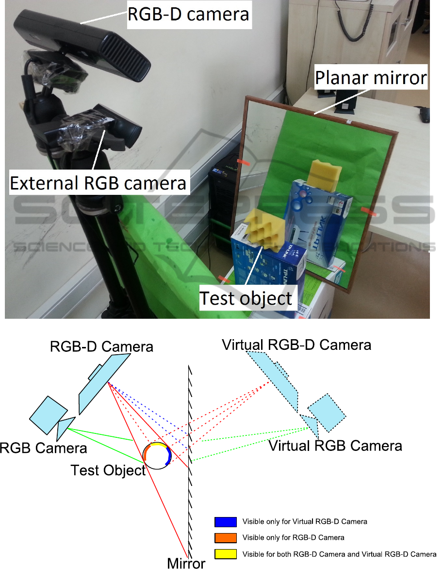
(a)
(b)
Figure 1: (a) The test system consists of an RGB-D and an RGB camera observing a test object and its reflection from a
planar mirror. (b) Imaging of a round test object with real and virtual RGB-D and RGB cameras.
VISAPP2014-InternationalConferenceonComputerVisionTheoryandApplications
326
depth sense limitations of the RGB-D cameras is one
of these difficulties and there are many applications
in which this limitation results in a system failure.
For example, reconstructing the 3D structure of a
scene is very common for narrow indoor areas such
as elevators or industrial production lines. More
specifically, in industry, reconstructing the 3D
structure of a product or package on a mass
production line is crucial for detecting
manufacturing defects. Multiple RGB-D cameras
can be used to construct the 3D structure of the
package and detect defects on it. However, camera
minimum depth sense range (50 cm for the Kinect)
is quite restrictive for covered production lines and
elevators (Canessa et al., 2013; Oliver et al., 2012).
In the covered production line case, one can barely
fit a single RGB-D camera to inspect products on the
conveyor belt. As a result, using multiple cameras
for such applications are prohibitive because of the
limited space.
Another interesting problem with multiple RGB-
D cameras is due to their active sensing technology.
All practical RGB-D cameras project infrared or
laser light to the scene to estimate the depth values.
In the multiple RGB-D camera case, each camera
projects its own patterns to the scene. These patterns
are accumulated on the overlapped scene surfaces,
which causes interference problems among these
patterns. This interference adds serious amount of
noise to the final depth values (Schröder et al., 2011;
Butler et al., 2012).
To overcome the mentioned difficulty, some
techniques have been developed. Schröder et al.
(2011) proposed a system of synchronized Kinects
which enables each Kinect to capture only its own
IR dot pattern. They used a fast rotating disk in front
of each IR projector so that only one Kinect would
project its IR dot pattern to the scene at a given time.
Another interesting solution is Butler et al.
(2012). The idea behind the system is to physically
vibrate an RGB-D camera using vibration motor.
Both IR projector and IR camera of the camera
move in harmony which means that depth sensing
works as normal with a little blur. However, IR dot
patterns of other cameras are sensed blurrily and
hence are neglected by other cameras. Therefore
each depth camera can sense the depth of the scene
almost without noise.
In this paper, we propose a novel method to
address the above problems for the 3D
reconstruction of a scene using a single or multiple
Kinect cameras. We utilize mirrors to create virtual
RGB-D cameras so that more views of a scene
would be visible from real and virtual RBG-D
cameras (Fig.1(a) and Fig. 1(b)). We define the
image of the scene from the mirror as a virtual
camera image. For example, in Fig. 1(b), the left
side of the test object (orange region) can be
reconstructed using real RGB-D camera, but the
right side of the test object (blue region) is not
visible from the real cameras. By placing a mirror
behind the test object, we can extract depth data of
the blue region which lets us successfully
reconstruct 3D structure of the object without
additional cameras.
Since each mirror introduces a different view
into the system, a more complete 3D reconstruction
of the scene can be achieved without any bandwidth,
synchronization, cost, and space limitation
problems. Our method captures the scene images
from the same RGB-D camera, so it uses the same
communication channel for real and virtual camera
views. This means that our method does not need
additional bandwidth for the virtual scene views.
Since there is only one RGB-D camera in the
system, we do not have any synchronization
problems between camera capture times. Adding a
planar mirror into the scene is much less expensive
than adding more cameras. As a result, our solution
is less expensive and it is more practical because
adding a planar mirror into the scene can be done by
just hanging a mirror on a wall without any need for
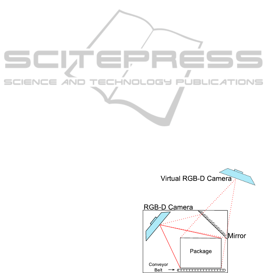
more depth space. Fig. 2 shows an example
configuration for such an application for a covered
production line. Note that placing a second RGB-D
camera on the location of virtual RGB-D camera is
impossible due to minimum depth sense range
restrictions.
Figure 2: Covered Production Line.
Our method does not address the pattern interference
problem, but it can be addressed by methods
3DReconstructionwithMirrorsandRGB-DCameras
327
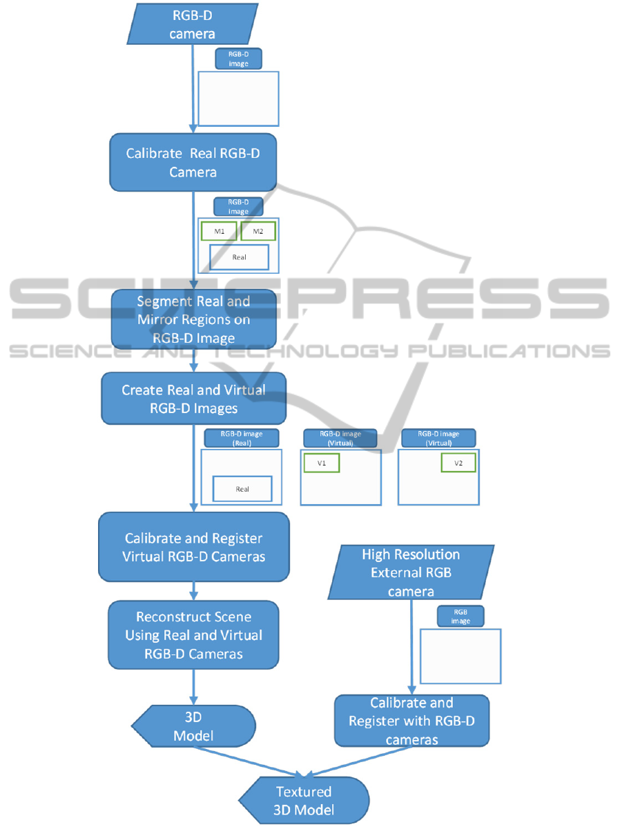
Figure 3: System overview of data flow and main processes.
VISAPP2014-InternationalConferenceonComputerVisionTheoryandApplications
328

introduced by (Schröder et al., 2011; Butler et al.,
2012). Finally, our method can also be used with
multiple RGB and RGB-D cameras if needed (Fig.
1-b).
There are other work that use mirrors with RGB
cameras to reconstruct observed scenes (Nene et al.,
1998; Mariottini et al., 2012). They build 3D
structure of a scene using Structure from Motion and
Stereo techniques. However, these methods are
strictly on RGB images and they do not develop any
solutions for the problems of RGB-D data such as
calibration and registration of depth images.
Using mirrors with RGB-D cameras is not a new
idea. There are attempts at using both Kinect and
mirrors but these studies are very informal (Kinect
vs. Mirror, 2010). They do not develop any
algorithms or formulations for the 3D reconstruction
of scenes.
Our main contribution in this paper is enabling
users to obtain a more complete 3D reconstruction
of an object from a single real depth image. Using a
proper configuration of mirrors and a single Kinect,
one can accomplish 3D reconstruction of an object
utilizing proposed method. We develop and test
algorithms for the simultaneous calibration and
registration of real and virtual RGB-D cameras. We
also describe methods for the full 3D reconstruction
of the scenes using the developed calibration
techniques. Although multiple calibration pattern
images with different positions and orientations can
be used to calibrate the proposed system, utilizing a
single image is found sufficient for the calibration
procedure. Furthermore, we used an external high
resolution RGB camera to capture high quality
images for texture mapping of the reconstructed 3D
structure of the object.
The rest of this paper is organized as follows: In
Section 2, we give an overview of our method. In
Section 3, we describe the calibration/registration
procedure between the RGB-D camera and RGB
camera. We then explain RGB-D camera - virtual
RGB-D camera calibration process. In Section 5, we
discuss experimental results of the proposed method.
Finally, we provide concluding remarks in Section 6.
2 METHOD OVERVIEW
The main processes and the data flow of the
proposed system are shown in Fig. 3. Our systems
begins with capturing the RGB-D images of the
scene with test or calibration objects. We then
calibrate the RGB-D camera using standard
calibration procedures. Next, the direct and the
reflected image sections of the RGB-D image are
segmented as real and virtual RGB-D images,
respectively. The calibration and registration of the
real and virtual images is followed by the 3D
reconstruction of the scene.
RGB-D cameras such as Microsoft's Kinect
cannot produce high quality RGB images because of
their low resolution and low quality lenses. In order
to increase the texture quality of the reconstructed
3D scene, we used an external high resolution RGB
camera along with the RGB-D camera (Fig. 1(b)). In
other words, we acquire depth data from the RGB-D
camera and color data from the external RGB
camera. So, we have four cameras in total; two of
them are real, two of them are virtual. Calibrating
these four cameras enables us to reconstruct the 3D
scene with a better texture mapping quality.
3 CALIBRATION
AND REGISTRATION
The first step of our method is constructing a test
area which is surrounded by single or multiple
mirrors. We place a calibration pattern on a location
which is visible from both RGB-D camera and
external RGB camera (Fig. 4 and Fig. 1(a)). Then,
we calibrate intrinsic and extrinsic parameters of the
real RGB-D camera and the real RGB camera using
the method of Zhang (2000). Next, we perform
registration between the RGB-D and the external
RGB camera using a method similar to (Jones et al.,
2011). Finally, the registration between the real and
virtual RGB-D cameras is established. Note that
intrinsic parameters of the virtual RGB-D camera
and the virtual RGB camera are identical with the
real counterparts, which makes the overall
calibration of the system easier compared to
calibration of multiple real cameras. Next two
subsections describe the details of the calibration
and the registration processes.
3.1 RGB-D and RGB Camera
Calibration
In order to compute the transformation between the
real RGB-D camera and the real external RGB
camera (Fig. 1(b)), we used the standard calibration
pattern (Fig. 4). There are total of 48 calibration
corners for a calibration pattern. For a given
calibration corner point C=
X, Y, Z
T
, the RGB-D
camera produces a 3D vector x
k
, y
k
, z
k
T
in the
3DReconstructionwithMirrorsandRGB-DCameras
329

Figure 4: Real and Virtual camera images of the
calibration plate. The lines show the correspondence
between the real and virtual pattern corners.
camera coordinate space. The image coordinates of
the point C on the image plane of the RGB-D
camera can be obtained by
x
kp
, y
kp
,1
T
=
1
z
k
x
k
, y
k
, z
k
T
, (1)
where x
kp
, y
kp
is the image point of C on the RGB-
D camera.
We define the intrinsic matrix of the RGB-D
camera as,
K=
f
x
0c
x
0f
y
c
y
001
.
(2)
The point C is projected on the RGB-D camera's
image plane by
x
k
y
k
z
k
=K
X
Y
Z
.
(3)
Multiplying both sides with K
-1
will lead,
K
-1
x
k
y
k
z
k
=
X
Y
Z
.
(4)
We multiply both sides with
1
z
k
then the equation
becomes,
K
-1
x
kp
y
kp
1
=
X/z
k
Y/z
k
Z/z
k
.
(5)
Using the above equation, one can reconstruct
the scene whose depth data is acquired from RGB-D
camera.
Since we know K
-1
and
x
kp
y
kp
1
, we can compute
X/z
k
Y/z
k
Z/z
k
T
.
Moreover, as Z
k
is already known from the
RGB-D depth data, the scale factor z
k
is easily
extracted which enables us to compute
X, Y, Z
T
.
Let x
r
, y
r
T
be the image of point C on the RGB
camera. At this point, we have a set of
X, Y, Z
T
and x
r
, y
r
T
correspondences which is
required to compute projection matrix between the
real world coordinates and the RGB camera. We
compute this projection matrix using the Singular
Value Decomposition (SVD) method.
3.2 RGB-D and Virtual RGB-D
Camera Calibration
In order to compute the transformation between the
real and virtual RGB-D cameras (Fig. 1(b)), we used
a two-sided calibration pattern whose corners are
projections of the same 3D point for all cameras
(Fig. 4).
Without loss of generality, we assume that the
camera reference frame of the real RGB-D camera is
the same as the world reference frame. Let
X, Y, Z
T
be the coordinate of the calibration
pattern corner C in RGB-D camera reference frame.
Let
X
v
, Y
v
, Z
v
T
be the coordinate of C in virtual
RGB-D camera reference frame. We can compute
X
v
, Y
v
, Z
v
T
with the method mentioned in the
previous subsection (Eq. 5).
C=
X, Y, Z
T
and C
v
=
X
v
, Y
v
, Z
v
T
vectors
refer to the same calibration pattern corner in
different reference frames; real and virtual RGB-D
camera reference frames, respectively. This is
because we used a two-sided calibration pattern to
capture the calibration points (Fig. 5). Hence the
transformation between the reference frames of the
RGB-D and the virtual RGB-D camera can be
computed utilizing these correspondences.
We follow the procedure described by (Besl et
al., 1992) to calculate the rotation matrix and the
translation vector between the reference frames of
real and virtual RGB-D cameras. Let Cen be the
centroid of the corners points of the RGB-D camera.
Similarly, let Cen
v
be the centroid of the corner
points of the virtual RGB-D camera.
Cen =
1
N
∑
C
i
N
i=1
.
Cen
v
=
1
N
∑
C
v
i
N
i=1
.
(6)
VISAPP2014-InternationalConferenceonComputerVisionTheoryandApplications
330
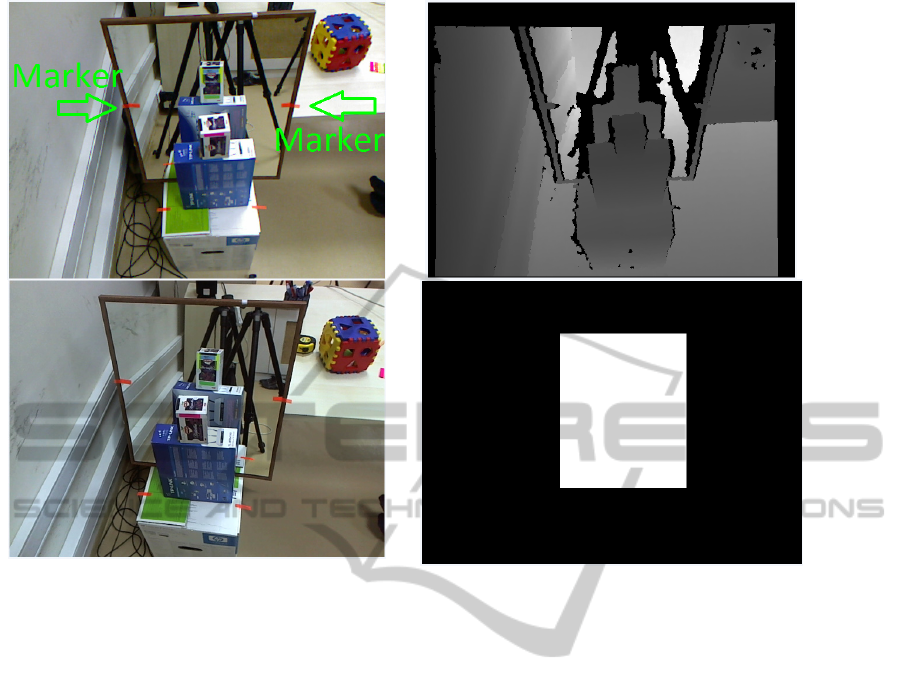
Figure 5: RGB-D camera's RGB image (top-left), RGB-D camera's depth image (top-right), external RGB image
(bottom-left) and current workspace mask (bottom-right).
Where C
i
and C
v
i
are the i
th
corner points of the real
and virtual cameras, respectively. N is the number of
points in the point set.
We accumulate point-centroid distances in the
3x3 matrix H,
H=
∑
C
i
-Cen .
N
i=1
( C
v
i
-Cen
v
)
T
,
(7)
where . represents matrix multiplication. By
decomposing H using SVD we obtain,
U,S,V
=SVD
H
.
(8)
The rotation matrix R can be computed as,
R=VU
T
,
(9)
and translation vector T can be computed using,
T=-R Cen+ Cen
v
.
(10)
Now, we have R and T between RGB-D and
virtual RGB-D camera reference frames. To
transform a 3D point from the RGB-D camera
reference frame to the virtual RGB-D camera
reference frame, following formula can be used
C
v
= RC + T.
(11)
4 RECONSTRUCTION
In the 3D reconstruction phase, we first acquire the
depth image from the RGB-D camera. RGB images
are obtained from both RGB-D and external RGB
cameras. In order to determine which regions of
images belong to the real scene and which belong to
the virtual scene (mirror regions), we place markers
on the borders of the mirror frame (Fig. 5). We
locate marker positions on the RGB image of the
RGB-D camera. As we have already registered the
depth and the RGB cameras of the RGB-D camera,
we can transform pixel coordinates of the markers
from RGB image reference frame to depth image
reference frame. Then, we get the depth value of the
markers. The surface points whose depth values are
lower than marker's depth value are assumed to
belong to the real scene and others are assumed to
belong to the virtual scene, which are actually
reflections of the real objects on the mirror. After
separating real and virtual surface points, we
reconstruct the real surface points using eq. (5) and
build a point cloud with these points. We achieve
3DReconstructionwithMirrorsandRGB-DCameras
331
reconstruction of virtual surface points via the same
technique that we use for the real surfaces. Next, we
transform the reconstructed virtual surface points
from the virtual RGB-D camera reference frame to
the real RGB-D camera reference frame using
Eq.11. Finally, we merge the transformed virtual
surface points with the point cloud constructed using
the real surface points. Overlapped regions which
are visible from both real and virtual RGB-D
cameras are not specially treated, which means that
for some object sections, there might be more than
one 3D reconstruction point. After the
reconstruction, we find the color value of each 3D
point using the method described in section 3.1.
Table 1: Calibration and reconstruction results.
Avg Err Std Dev
Ext. Cam. - Real
RGB-D camera
1.68 px 1.21 px
Real - Virtual RGB-D
camera
5.00 mm 2.39 mm
Real - Reconstructed
distance
4.21 mm 3.05 mm
5 EXPERIMENTAL RESULTS
In order to show quantitative results of our method
we conducted some experiments. We reconstructed
3D points that correspond to calibration plate
corners and projected these points onto the RGB
camera image plane to measure the external RGB
and RGB-D camera calibration error (Fig. 4). The
average distance between the projected 3D points
and detected corner pixels (Ground truth) is
presented in the first row of Table 1 with standard
deviation. Next, we repeated the same experiment
between the real and virtual RGB-D cameras. We
reconstructed two sets of 3D points using the
calibration plate corners from the real RGB-D
camera and the virtual RGB-D camera. Then, we
transform set of virtual 3D points from the virtual
RGB-D camera reference frame to the real RGB-D
camera reference frame to calculate the
transformation error. The second row of Table 1
contains the average distance between the
transformed 3D points and the ground truth 3D
points and its standard deviation.
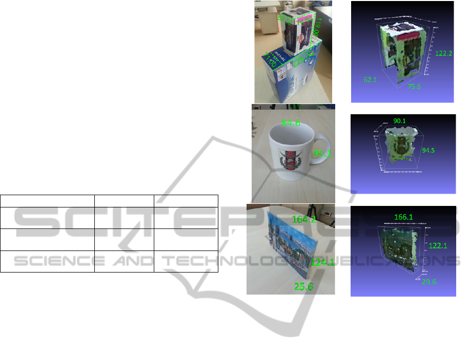
Finally, we compare reconstructed object size
measurements with the ground truth object size
measurements. The ground truth object size
measurements were obtained by using a standard
caliper tool on the real world objects. The last row of
Table 1 shows the average difference between the
Figure 6: Ground truth measurements (mm) of the test
object (left), Distances measured by our method (right).
reconstructed distances and the ground truth
distances with standard deviation. Fig. 6 shows some
of the test objects used to assess our system. Note
that, without using our virtual RGB-D camera setup,
these types of measurements are very difficult to
obtain from a single depth map image.
We also provide qualitative results for some 3D
reconstruction examples in Fig. 7. Left column
represents RGB image of the objects, middle column
and right column represent frontal and rear view of
reconstructed 3D objects, respectively.
6 CONCLUSIONS
The availability of the RGB-D cameras made the 3D
reconstruction tasks much easier compared to earlier
systems. Using multiple RGB-D cameras are now
becoming more popular for a more complete 3D
reconstruction. We presented a new method that
uses RGB-D cameras with mirrors to prevent a
number of known problems such as synchronization,
physical space limitations, bandwidth limitations,
and inherent costs. We provided formulations for the
calibration and registration of multiple real and
VISAPP2014-InternationalConferenceonComputerVisionTheoryandApplications
332

virtual RGB-D and RGB cameras. We also provided
formulations for the reconstruction task from the
obtained data. Our method is capable of producing
reconstruction results with higher texture quality by
employing an external high resolution RGB camera.
One drawback of our method is that, the real and
virtual cameras have to share the same image space
which introduces a resolution problem. In addition,
the depth noise from virtual RGB-D camera will
increase due to the increased distance. However, this
problem will be less important as higher resolution
RGB-D cameras become available. The experiments
performed on real test objects showed qualitatively
and quantitatively that our method is very effective
in practice.
ACKNOWLEDGEMENTS
This work is supported by TUBITAK Project
112E127.
REFERENCES
Smisek, Jan, Michal Jancosek, and Tomas Pajdla. "3D
with Kinect." Consumer Depth Cameras for Computer
Vision. Springer London, 2013. 3-25.
Henry, Peter, et al. "RGB-D mapping: Using Kinect-style
depth cameras for dense 3D modeling of indoor
environments." The International Journal of Robotics
Research 31.5 (2012): 647-663.
Khoshelham, Kourosh, and Sander Oude Elberink.
"Accuracy and resolution of kinect depth data for
indoor mapping applications." Sensors 12.2 (2012):
1437-1454.
Izadi, Shahram, et al. "KinectFusion: real-time 3D
reconstruction and interaction using a moving depth
camera." Proceedings of the 24th annual ACM
symposium on User interface software and technology.
ACM, 2011.
Rusu, Radu Bogdan, and Steve Cousins. "3d is here: Point
cloud library (pcl)."Robotics and Automation (ICRA),
2011 IEEE International Conference on. IEEE, 2011.
Canessa, Andrea, et al. "Calibrated depth and color
cameras for accurate 3D interaction in a stereoscopic
augmented reality environment." Journal of Visual
Communication and Image Representation (2013).
Oliver, Ayrton, et al. "Using the Kinect as a navigation
sensor for mobile robotics." Proceedings of the 27th
Conference on Image and Vision Computing New
Zealand. ACM, 2012.
Lai, Kevin, et al. "A large-scale hierarchical multi-view
rgb-d object dataset."Robotics and Automation
(ICRA), 2011 IEEE International Conference on.
IEEE, 2011.
Sumar, Lazar, and Andrew Bainbridge-Smith. "Feasibility
of Fast Image Processing Using Multiple Kinect
Cameras on a Portable Platform." Department of
Electrical and Computer Engineering, Univ.
Canterbury, New Zealand.
Hossny, M., et al. "Low cost multimodal facial recognition
via kinect sensors."LWC 2012: Potent land force for a
joint maritime strategy: Proceedings of the 2012 Land
Warfare Conference. Commonwealth of Australia.
Schröder, Y., Scholz, A., Berger, K., Ruhl, K., Guthe, S.,
& Magnor, M. (2011). Multiple kinect
studies. Computer Graphics.
Butler, D. Alex, et al. "Shake'n'sense: reducing
interference for overlapping structured light depth
cameras." Proceedings of the 2012 ACM annual
conference on Human Factors in Computing Systems.
ACM, 2012.
Nene, Sameer A., and Shree K. Nayar. "Stereo with
mirrors." Computer Vision, 1998. Sixth International
Conference on. IEEE, 1998.
Mariottini, Gian Luca, et al. "Planar mirrors for image-
based robot localization and 3-D
reconstruction." Mechatronics 22.4 (2012): 398-409.
"Kinect vs. Mirror,"
http://www.youtube.com/watch?v=1Qx8NzuSSJ4
Zhang, Z. 2000. A flexible new technique for camera
calibration. IEEE TPAMI, 22(11):1330–1334.
Jones, Brett R. Augmenting Complex Surfaces With
Projector-Camera Systems. Diss. University of
Illinois, 2011.
Besl, Paul J., and Neil D. McKay. "Method for registration
of 3-D shapes." Robotics-DL tentative. International
Society for Optics and Photonics, 1992.
3DReconstructionwithMirrorsandRGB-DCameras
333
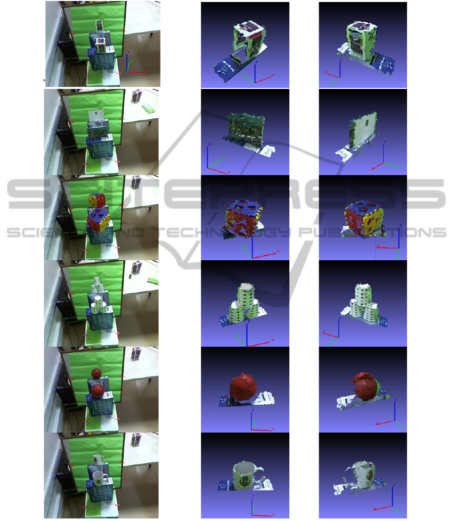
APPENDIX
Figure 7: Reconstruction results.
VISAPP2014-InternationalConferenceonComputerVisionTheoryandApplications
334
