Compressor Design for a 30fs-300J 10PW Ti:sapphire Laser
Divided-compressor with an Object-Image-Grating Self-tiling Tiled Grating
Zhaoyang Li
1
, Tao Wang
1
, Guang Xu
2
and Yaping Dai
1
1
Shanghai institute of laser plasma, No. 1129 chenjiashan Road, Jiading, Shanghai, China
2
Shanghai institute of optics and fine mechanics, No. 390 qinghe Road, Jiading, Shanghai, China
Keywords: 10PW Laser, Chirped-Pulse Amplification, Grating Compressor, Tiled Grating, Dispersion, Self-Phase
Modulation.
Abstract: A 30fs-300J Ti:sapphire laser need an optimized compressor to compress the 8ns/90nm deep chirped long
pulse to 30fs. We proposed a compressor design, which reduces the grating number, grating size, vacuum
compression chamber cubage, and system complexity by using a divided-compressor structure and an
object-image-grating self-tiling method.
1 INTRODUCTION
Femtosecond 10 petawatt (PW) lasers are being
planned and constructed recently in the worldwide.
A 30fs-300J 10PW laser based on Ti:sapphire is
right now under plan in China. This system will use
the well-known chirped-pulse amplification (CPA)
technique to support its output capability (Mourou,
1988).
The primary design of the system linear chirped
ratio is around 8ns/90nm. Therefore, the pulse
compression process will be challenged by several
problems, including large-size gratings, long
compression distance, and huge vacuum
compression chamber (Kramer, 2013). In this paper,
we attempt to give a basic compressor design to
solve the above problems.
2 COMPRESSOR STRUCTURE
The primary parameter of the positive chirped pulse
after the amplification chain is given by Tab.1. And
the compressor should compress the 400J, 8ns
chirped pulse to less than 30fs.
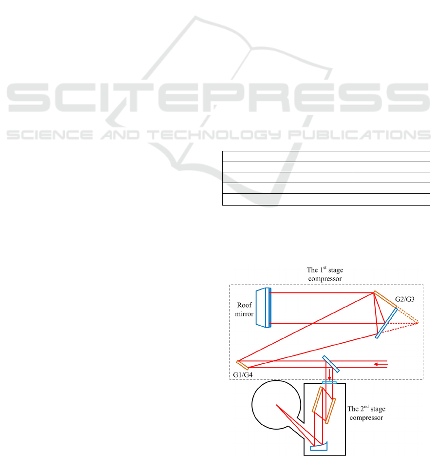
In order to reduce the vacuum chamber, as
shown in Fig.1, the treacy compressor (Treacy, 1969)
will be divided into two compressors: a double-pass
and a single-pass grating pairs are used as the 1
st
stage and the 2
nd
stage compressors, which are
located in air and a vacuum chamber, respectively.
Table 1: Beam parameter after the amplification chain.
Centre wavelength 800nm
FWHM 90nm
Single pulse energy 400J
Duration 8ns
Beam diameter
Φ150mm
The compression pulse from the 1
st
stage compressor
is delivered via a fused silica window into the
vacuum chamber and is further compressed by the
2
nd
stage compressor.
Figure 1: Divided-compressor design.
The thickness of the fused silica window is
191
Li Z., Wang T., Xu G. and Dai Y..
Compressor Design for a 30fs-300J 10PW Ti:sapphire Laser - Divided-compressor with an Object-Image-Grating Self-tiling Tiled Grating.
DOI: 10.5220/0004679701910195
In Proceedings of 2nd International Conference on Photonics, Optics and Laser Technology (PHOTOPTICS-2014), pages 191-195
ISBN: 978-989-758-008-6
Copyright
c
2014 SCITEPRESS (Science and Technology Publications, Lda.)
designed as 20mm to balance the air pressure and
the nonlinear effect. The compressed duration of the
1
st
stage compressor is a key paramter, which need
to be shorter enough to reduce the 2
nd
stage
compressor, as well as the vacumm chamber, but
longer enough to avoid the pulse distortion, fused
silica damage, air ionization, and so on. Generally,
the requirement of the pulse temporal and spatial
distortion by self-phase modulation (B integral) and
self-focusing is higher than that of the others.
Therefore, the B integral should be as small as
possible, and the beam breakup distance must be
much longer than the window thickness. The beam
breakup distance can be given by
2
z
G
nkI
(1)
where G is a coefficient from 3 to 10 depended on
different cnditions. Here we choose 3 to leave the
largest margin.
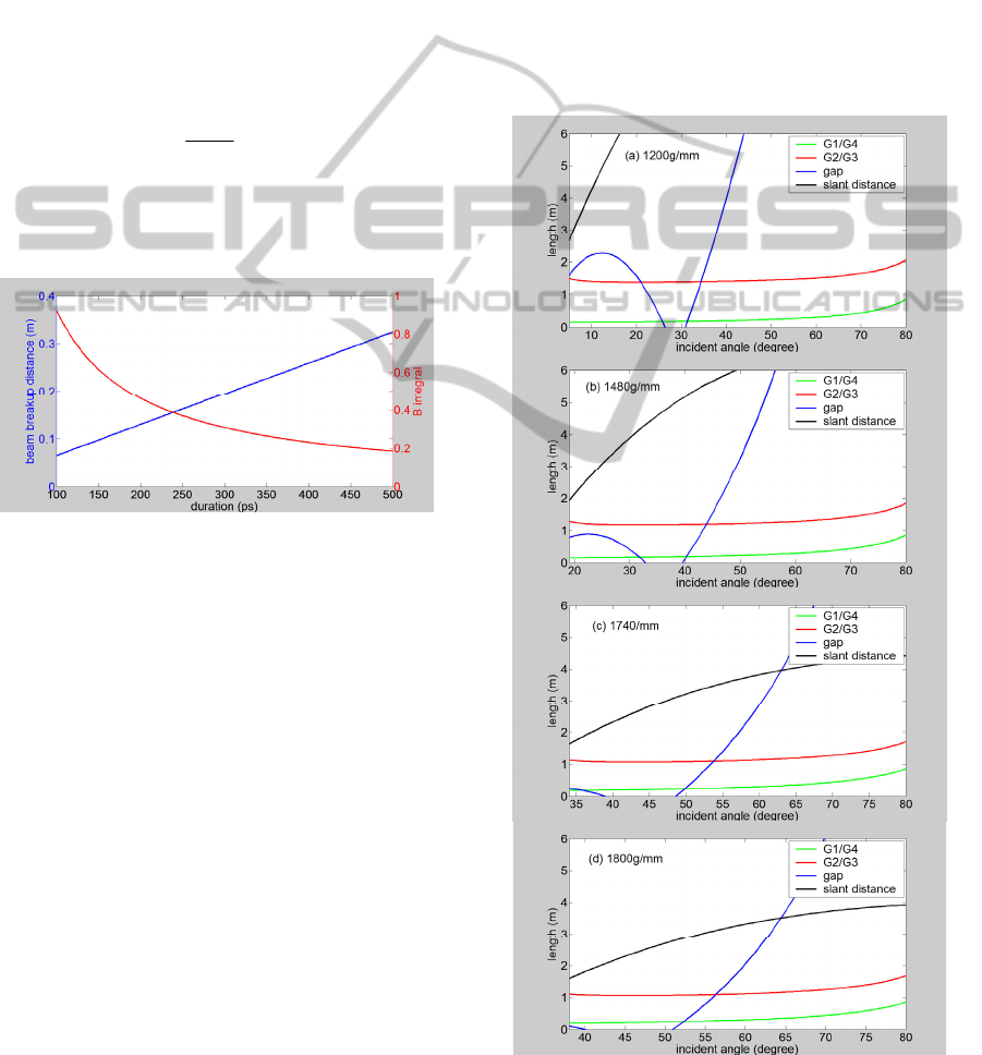
Figure 2: B integral and beam breakup distance versus
duration.
The evolution of B integral and beam breakup
distance for pulse duration is given by Fig. 2, and
the 300ps is chosen. Accordingly, the B integral is
0.3, and the beam breakup distance is 0.2m. The
intensity is 6GW/cm
2
which is below the 10GW/cm
2
threshold of air ionization, and the fluence is
1.84J/cm
2
that is below the 20J/cm
2
threshod of
fused silica damage for a 300ps pulse (Stuart, 1995).
3 PARAMETER OPTIMIZATION
3.1 The 1
St
Stage Compressor
Beside of the output parameters of a laser beam from
the amplification chain, there are many other
parameters determine the geometry of a treacy
compressor, such as unclipping spectrum range,
part-clipping spectrum range, grating groove density,
grating size, slant distance of grating pair, beam
incident angle, and so on. The grating groove
density and the incident angle are two basic
parameters which influence the other ones, and in
this section we will calculate parameters of the 1
st
stage compressor by choosing a suitable grating
groove density and an optimized incident angle.
The unclipping spectrum range of our design is
set as 90nm around the centre wavelength to allow
the FWHM passing without clipping. The design of
a treacy compressor must satisfy some limitation
conditions:
Grating equation;
Grating-beam overlap;
Sufficient wide spectrum window.
Figure 3: Grating size, gap and slant distance for 1200,
1480, 1740 and 1800 g/mm versus incident angle.
PHOTOPTICS2014-InternationalConferenceonPhotonics,OpticsandLaserTechnology
192
This design is based on the broad bandwidth 800nm
dielectric grating due to high damage threshold and
wide spectral range (Martz, 2009) and (Wang, 2010),
therefore types of available groove density include
1200g/mm, 1480g/mm, 1740g/mm and 1800g/mm.
Fig.3 shows the evolution of beam-grating gap,
grating size (a tradition single-pass 4-grating
compressor with the 1
st
, 2
nd
, 3
rd
, and 4
th
grating G1,
G2, G3, and G4. G1&G4 and G2&G3 have some
sizes, respectively.), and grating pair slant distance
for various amounts of incident angle with different
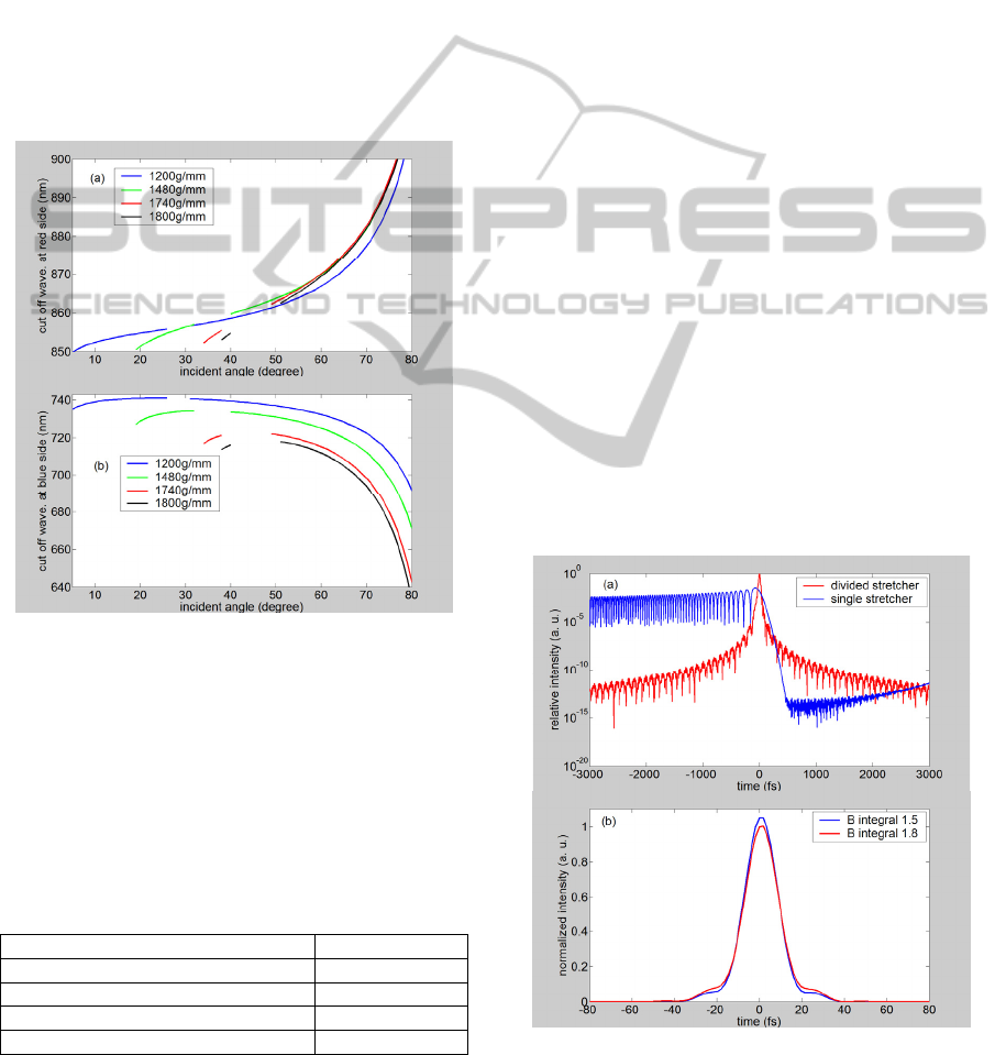
grating groove densities. And Fig.4 gives the
evolution of cut off wavelength of the part-clipping
spectrum range for various values of incident angle
with four types of grating groove density.
Figure 4: Cut off wavelength of the part-clipping spectrum
range for 1200, 1480, 1740 and 1800 g/mm versus
incident angle.
Our chosen principles of grating groove density
and incident angle include: relatively large beam-
grating gap, short length of grating and slant
distance, and wide range of part-clipping spectrum
range. And the optimized parameters are given by
Tab.2.
Table 2: Optimized 1
st
stage compressor parameter.
Grating density (g/mm) 1740
Incident angle (degree) 52
Grating size (m) 1.10
Slant distance (m) 3.37
Wavelength range (nm) 721-864
According to Martz’s work, the high diffraction
efficiency spectrum window of the broad bandwidth
dielectric grating is relative to the incident angle,
and the 52 degree incident angle could meet the
requirement of 721-864nm spectrum window.
To avoid the first grating damage where a short
pulse is achieved, a large incident angle is preferred.
The fluence with the optimized 52 degree incident
angle is 1.13J/cm
2
(below the 1.76J/cm
2
damage
threshold for a 120ps pulse reported by Martz).
3.2 The 2
nd
Stage Compressor
The 2
nd
stage compressor needs to dechirp the rest
chirp, and a 30fs short pulse will be obtained after it.
Hence, it is very easy to cause a grating damage. In
femtosecond regime, the damage threshold of the
broad bandwidth dielectric grating (0.18J/cm
2
for a
120fs pulse reported by Martz) is lower than that of
the gold coated grating (0.6J/cm
2
). Thus, Horiba
Jobin Yvon’s gold coated gratings are used in the
design of the 2
nd
stage compressor. The 0.6J/cm
2
damage threshold determines the smallest incident
angle is 71 degree. A 74 degree incident angle is
chosen to make the fluence 0.5J/cm
2
. Because of the
small spatial chirp, a single-pass parallel grating pair
is designed as the 2
nd
stage compressor. And the
other parameters are 1740g/mm grating groove
density, 0.336m slant distance, 0.544m grating size,
0.37m grating-beam gap, and 95-1078nm spectrum
range.
3.3 Dispersion and B Integral
Figure 5: (a) Compression pulse with and without 3
rd
dispersion compensation. (b) Compression pulse with and
without extra 0.3 B integral.
CompressorDesignfora30fs-300J10PWTi:sapphireLaser-Divided-compressorwithanObject-Image-Grating
Self-tilingTiledGrating
193
The non-equivalent incident angles of the 1
st
and 2
nd
stage compressors will lead to a big amount of
uncompensated 3
rd
dispersion, and the nonlinearity
effect within the fused silica window would
introduce self-phase modulation (B integral), hence
these two factors will distort the compression pulse
temporal profile.
Fig. 5 (a) shows the compression pulses with a
single-stretcher and with a divided-stretcher,
respectively. The incident angle and the grating
groove density of the single-stretcher are equivalent
to those of the 1
st
stage compressor. The 2
nd
dispersion of the single-stretcher-divided-
compressor system could be compensated, but the
3
rd
dispersion cannot be eliminated completely. In
this way, a divided-stretcher is designed to match the
divided-compressor to compensate both the 2
nd
, 3
rd
,
and 4
th
order dispersion. The incident angle, the
grating groove density, and the chirped ratio of the
divided-stretcher and those of the divided-
compressor are matched exactly. Moreover, the
divided-stretcher has another advantage: the smaller-
stretcher can be precisely adjusted to match the 2
nd
order dispersion of the whole system without
changing the larger-stretcher and the divided-
compressor.
Besides, we could also adjust the incident angle
of the single-stretcher to compensate both the 2
nd
and the 3
rd
but the 4
th
order dispersion within the
single-stretcher-divided-compressor system.
The control purpose of the B integral within the
amplification chain is 1.5. Fig. 5(b) shows the
compression pulse with a 1.8 B integral added the
influence of the fused silica window, and this
distortion is acceptable.
4 TILED GRATING
The requirement size of the second grating in the 1
st
stage compressor is 1.1m. However, the largest size
of the available grating is 0.56m. Therefore, the
object-image-grating self-tiling method is used to
double the effective grating size to 1.1m, and the
size of the corresponding mirror is 0.8m (Li, 2010).
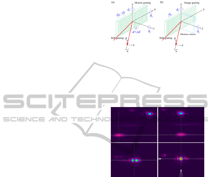
The object-image-grating self-tiling method is a
very easy way to enlarge the effective grating size,
as shown in Fig.6, which reduce the number of tiling
errors within a tiled grating from 6 to only 3.
Besides, the tiling condition monitoring of the
proposed compressor design, as shown in Fig.1, is
very convenient, which can be achieved only by
observing the distribution of the main beam focal
spot. Unlike the traditional grating tiling, no
Figure 6: Degrees of freedom within (a) a tradition grating
tiling and (b) an object-image-grating self-tiling.
additional monitoring lasers are needed in a
compressor with only one tiled grating. And a
similar demonstration experiment is shown in Fig.7,
we just need 3 steps to achieve an ideal object-
image-grating self-tiling tiled grating by adjusting
y,
z, and
x (illustrated by Fig.6) one by one.
Figure 7: Steps to achieve the ideal tiling condition.
5 CONCLUSIONS
A divided-compressor is designed for a 30fs-300J
10PW Ti:sapphire laser to compress the 8ns/90nm
deep chirped laser pulse. This design could satisfy
the 30fs-300J compression requirement. The number
and the size of gratings, the cubage of the vacuum
compression chamber, and the complexity of the
system are reduced.
ACKNOWLEDGEMENTS
This work was supported by the National Natural
Science Foundation of China under project
11304296.
PHOTOPTICS2014-InternationalConferenceonPhotonics,OpticsandLaserTechnology
194

REFERENCES
P. Maine, D. Strickland, P. Bado, M. Pessot, and G.
Mourou, 1988. Generation of ultrahigh peak power
pulses by chirped pulse amplification. IEEE Journal of
Quantum Electronics vol. 24, pp 398.
D. Kramer, J. Novák, and B. Rus, 2013. Hybrid
compressor design for a 10PW laser. EPJ Web of
Conferences 48, 00010.
E. B. Treacy, 1969. Optical pulse compression with
diffraction gratings. IEEE Journal of Quantum
Electronics vol. QE-5, pp 454.
B. C. Stuart, M. D. Feit, A. M. Rubenchik, B. W. Shore,
and M. D. Perry, 1995. Laser-induced damage in
dielectrics with nanosecond to subpicosecond pulses.
Physical Review Letters vol. 74, pp 2248.
D. H. Martz, H. T. Nguyen, D. Patel, J. A. Britten, D.
Alessi1, E. Krous, Y. Wang, M. A. Larotonda, J.
George, B. Knollenberg, B. M. Luther, J. J. Rocca and
C. S. Menoni, 2009. Large area high efficiency broad
bandwidth 800nm dielectric gratings for high energy
laser pulse compression. Optics Express vol. 17, pp
23809.
J. Wang, Y. Jin, J. Ma, T. Sun, and X. Jing, 2010. Design
and analysis of broadband high-efficiency pulse
compression gratings. Applied Optics vol. 49, pp 2969.
Z. Li, G. Xu, T. Wang, and Y. Dai, 2010. Object-image-
grating self-tiling to achieve and maintain stable, near-
ideal tiled grating conditions. Optics Letters vol. 35,
pp 2206.
CompressorDesignfora30fs-300J10PWTi:sapphireLaser-Divided-compressorwithanObject-Image-Grating
Self-tilingTiledGrating
195
