
Face Pose Tracking under Arbitrary Illumination Changes
Ahmed Rekik
1
, Achraf Ben-Hamadou
2
and Walid Mahdi
1
1
Sfax University, Multimedia InfoRmation systems and Advanced Computing Laboratory (MIRACL)
P
ˆ
ole Technologique de Sfax, route de Tunis Km 10, BP 242, 3021 Sfax, Tunisia
2
Total Immersion SA, R&D department, 26 Avenue du G
´
en
´
eral Charles de Gaulle, 92150 Suresnes, France
Keywords:
3D Face Tracking, RGB-D Cameras, Lighting Condition Changes, Augmented Reality, Human Computer
Interaction.
Abstract:
This paper presents a new method for 3D face pose tracking in arbitrary illumination change conditions using
color image and depth data acquired by RGB-D cameras (e.g., Microsoft Kinect, Asus Xtion Pro Live, etc.).
The method is based on an optimization process of an objective function combining photometric and geometric
energy. The geometric energy is computed from depth data while the photometric energy is computed at each
frame by comparing the current face texture to its corresponding in the reference face texture defined in
the first frame. To handle the effect of changing lighting condition, we use a facial illumination model in
order to solve which lighting variations has to be applied to the current face texture making it as close as
possible to the reference texture. We demonstrate the accuracy and the robustness of our method in normal
lighting conditions by performing a set of experiments on the Biwi Kinect head pose database. Moreover,
the robustness to illumination changes is evaluated using a set of sequences for different persons recorded in
severe lighting condition changes. These experiments show that our method is robust and precise under both
normal and severe lighting conditions.
1 INTRODUCTION
Face 3D pose tracking is an important topic for sev-
eral research domains such as Human-computer in-
teraction, augmented reality, etc. (Yin et al., 2006).
These very last years, the research in this topic has
dramatically increased (Fanelli et al., 2013; Padeleris
et al., 2012; Cai et al., 2010). This arises particularly
from the ubiquity of vision systems in our day life
(i.e., webcams in laptops, smart-phones, etc.) and,
recently, from the availability of low-cost RGB-D
cameras, such as Asus Xtion Pro Live and Microsoft
Kinect. The literature contains several works on face
pose estimation and tracking (see (Murphy-Chutorian
and Trivedi, 2009) for a survey). Since lighting con-
ditions are rarely constant, the accuracy of the meth-
ods using 2D images are very sensitive to illumination
changes. To solve this problem, Zhou et al.. (Zhou
et al., 2004) impose a rank constraint on shape and
albedo for the face class to separate the two from il-
lumination using a factorization approach. Integra-
bility and face symmetry constraints are employed to
fully recover the class specific albedos and surface
normals. Some recent works like (Fanelli et al., 2013;
Padeleris et al., 2012) use depth images, but this solu-
tion is incomplete since depth data are also noisy for
low-cost RGB-D cameras and the solution is to use
both depth and color images to perform the tracking
(Baltru
ˇ
saitis et al., 2012; Rekik et al., 2013).
In addition to the combination of color and depth
images, we propose in this paper a new 3D face track-
ing method that takes in account lighting condition
changes. Our method uses a generic illumination
model and does not require to characterise the light
sources (e.g., number, power, pose). The rest of the
paper is organized as follows. In the first section, we
describe the input data acquired from RGB-D camera.
Section 3 details the proposed tracking method where
first we present the general framework, then, we de-
scribe the illumination changes model. Finally, Sec-
tion 4, details the experiments and results to evaluate
the tracking accuracy of our method and its robustness
against arbitrary illumination changes.
2 INPUT DATA DESCRIPTION
In this work, we have used a Kinect sensor as a RGB-
D camera. Its depth sensor is a composed device con-
570
Rekik A., Ben-Hamadou A. and Mahdi W..
Face Pose Tracking under Arbitrary Illumination Changes.
DOI: 10.5220/0004686705700575
In Proceedings of the 9th International Conference on Computer Vision Theory and Applications (VISAPP-2014), pages 570-575
ISBN: 978-989-758-009-3
Copyright
c
2014 SCITEPRESS (Science and Technology Publications, Lda.)
sisting of an IR projector of a point pattern (point
structured-light) and IR camera surrounding the color
camera, which are used to triangulate points in space
leading to a depth map (Ben-Hamadou et al., 2010;
Ben-Hamadou et al., 2013; Smisek et al., 2013). As
illustrated in Figure 1, one can compute the 3D point
cloud corresponding to the depth map pixels using the
calibration parameters of the IR camera. Also, each
3D point can be projected in the color image using
the calibration parameters of the color camera. In this
way, we have all transformations to map data between
3D space, color image, and depth map. For the rest of
this paper we assume that all the calibration parame-
ters of the RGB-D sensors are known.
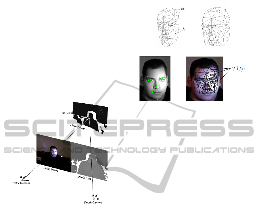
Depth map
Color image
Point Cloud
Color Camera
Depth Camera
3D point
Figure 1: Illustration of the RGB-D camera geometry.
3 FACE POSE TRACKING
METHOD
The 3D face tracking can be seen as an optimization
problem where the goal is to find the optimal 3D rigid
motion of the face between two consecutive acqui-
sitions. In this process, we denote the optimal face
pose as
b
x
t
in the instant t, where
b
x
t
∈ R
6
involves the
6 DOF (i.e., 3 translations and 3 rotation angles) of a
3D rigid motion. For each acquisition, the estimation
of the face pose is an iterative process witch amelio-
rate an incremental estimation
e
x
t
until reaching the
optimal estimation
b
x
t
. Initially,
e
x
t
is set to
b
x
t−1
(i.e.,
tracking result of the previous frame). Reaching the
optimal estimation consist of minimizing an objective
function f
ob j
measuring the distance between the ref-
erence model M
∗
and the appearance model M
e
x
t
:
b
x
t
= argmin
e
x
t
∈R
6
f
ob j
(M
∗
, M
e
x
t
) (1)
(a) (b)
(c)
*
(d)
Figure 2: From the Candide model to the reference model
M
∗
. (a) Original Candide model defined as K = 113 vertices
v
k
and J = 184 faces f
j
. (b) The modified version of the
Candide model used in the rigid tracking process contain-
ing only K = 93 vertices J = 100 facets. This version cov-
ers only rigid parts of the face. (c) Facial reference points
extracted form the image using (Valstar et al., 2010). (d)
Texture of the reference model obtained from the color im-
age.
Each of these concepts forming the optimization pro-
cess will be detailed in the followings sections.
3.1 Reference Model
The reference model M
∗
used in this work is a tex-
tured 3D face model. Without loss of generality we
used the Candide model (Ahlberg, 2001). It is de-
fined as a set of K vertices V
∗
=
{
v
1
, v
2
, . . . , v
K
}
and
a set of J facets F
∗
=
{
f
1
, f
2
, . . . , f
J
}
(see figure 2(a)).
The initialization of the reference model consist of fit-
ting the Candide deformable model to the user’s face
by solving the shape variation parameters of the Can-
dide model and extracting its texture by projecting the
model in the 2D image of the first acquisition where
the face is supposed neutral expression and animation
(see (Valstar et al., 2010; Rekik et al., 2013) for more
details). First, facial reference points are detected in
the color image using (Valstar et al., 2010)(see Fig-
ure 2(c)). Using both of the calibration parameters of
Kinect and the depth map, one can retrieve 3D coor-
dinates of the detected reference points in the color
camera coordinate system. After this fitting step,
we keep in the model only facial parts that present
the minimum of animation and expression (see Fig-
ure 2(b)). The reference texture T
∗
is defined by the
set of textured facets
{
T
∗
( f
1
), T
∗
( f
2
), . . . , T
∗
( f
J
)
}
obtained by projecting the face model on the 2D im-
age (Figure 2(d) shows an example of a reference tex-
ture).
FacePoseTrackingunderArbitraryIlluminationChanges
571

3.2 Objective Function and
Optimization
The objective function allows the evaluation of a
given
e
x
t
by comparing the appearance face model
M
e
x
t
to the reference face model M
∗
. The appearance
model M
e
x
t
consists of a set of K vertices V
e
x
t
and a
set of J facets F
e
x
t
. The coordinates of each vertex
e
v
k
∈ V
e
x
t
are computed as follows:
e
v
k
= Rv
k
+ t (2)
where R and t are, respectively, the 3× 3 rotation ma-
trix and the translation vector generated in a standard
way from the six parameters of
e
x
t
. The appearance
texture T
e
x
t
is defined by the set of the textured facets
obtained by projecting the transformed face model on
the current 2D image.
Our objective function depends on two energies.
The first is a geometric energy E
geo
(V
e
x
t
, Q
t
) measur-
ing the closeness of the appearance model on the 3D
point cloud Q
t
acquired by the depth sensor of the
RGB-D camera in instant t. The second is a pho-
tometric energy denoted by E
ph
T
∗
, T
0
e
x
t
where T
0
e
x
t
is the modified appearance texture (will be explained
later in section 3.2.2). It indicates the similarity be-
tween textures of the reference model and the appear-
ance model M
e
x
t
. The combination of these two ener-
gies is given by:
f
ob j
(M
∗
,M
e
x
t
)=α E
geo
(
V
e
x
t
,Q
t
)
+ (1−α) E
ph
T
∗
,T
0
e
x
t
(3)
where α is a weighting scalar which we experimen-
tally fixed to 0.8 in our implementation. We refer the
reader to (Rekik et al., 2013) for more details about
α.
3.2.1 Geometric Energy
The geometric energy indicates the closeness of the
appearance model M
e
x
t
to the point cloud Q
t
acquired
at a time t and compares their shapes. Given the cal-
ibration data of the RGB-D camera, we can define a
set of K corresponding points {(
e
v
k
, q
k
)}
K
k=1
between
the vertices V
e
x
t
of M
e
x
t
and the point cloud Q
t
, where
q
k
∈ Q
t
,
e
v
k
∈ V
e
x
t
, and q
k
is the closest 3D point to
e
v
k
.
The geometric energy is defined as the point-plan dis-
tance between V
e
x
t
and Q
t
:
E
geo
(V
e
x
t
, Q
t
) =
1
K
K
∑
k=1
kn
T
k
(
e
v
k
− q
k
)k
2
, (4)
where n
k
is the surface normal at
e
v
k
. In equation 4,
more V
e
x
t
is close to Q
t
, more the geometric energy
tends toward 0.
3.2.2 Photometric Energy
This energy allows the optimization process to con-
verge toward a face pose with a texture T
e
x
t
as close
as possible to the reference one T
∗
. The photometric
energy is defined as follows:
E
ph
(T
∗
, T
e
x
t
) =
1
N
∑
p
∗
i
∈T
∗
[T
e
x
t
(w(p
∗
i
)) − T
∗
(p
∗
i
)]
2
(5)
where p
∗
i
is a pixel in T
∗
, N is the number of pix-
els in T
∗
and w(p
∗
i
) is a function which compute for
each p
∗
i
its corresponding one in T
e
x
t
. For more de-
tails about computing correspondence between pixels
in triangular regions see (Maurel, 2008).
Since the image acquired in the instant t can be af-
fected by an arbitrary illumination changes, the pho-
tometric energy can give a false assessment. To re-
duce the effect of changing lighting condition, we
propose to use a facial illumination model inspired
from (Silveira and Malis, 2007). For face pose track-
ing, we are interested to solve which lighting varia-
tions has to be applied to the current texture T
e
x
t
in
order to obtain a modified texture T
0
e
x
t
whose illumi-
nation conditions are as closely as possible to those
at the time of initializing T
∗
. We propose to formu-
late this problem so as to find an element-wise multi-
plicative lighting variation
e
I over the current T
e
x
t
, and
a global lighting changes β, such that T
0
e
x
t
matches as
closely as possible to T
∗
:
T
0
e
x
t
=
e
I ◦ T
e
x
t
+ β (6)
where the operator ◦ stands for the element-wise
product. Since considering that the intensity of each
pixel can change independently, we have an observ-
ability problem. We suppose that
e
I is modelled by
a parametric surface
e
I = f (p
i
;γ), ∀p
i
, that describes
the local illumination variation of each pixel. Vec-
tor γ gives the different lighting variation multiplica-
tive values γ
j
relative to pixels in a same texture sub-
region R
j
. These texture sub-regions describes the re-
gions in the face for which the illumination variation
is linear. Thus,
e
I reads:
e
I = f (p
i
;γ) = γ
j
, ∀p
i
∈ R
j
(7)
where p
i
denotes the i-th pixel of the j-th subregion
R
j
. In practice, the appearance texture T
e
x
t
is dis-
cretized into n subregions R
j
, j = 1, 2, . . . , n, where
each R
j
is defined as a set of adjacent triangles in T
e
x
t
.
Figure 3 shows an example of discretization of T
e
x
t
into 4 subregions. Using equation 7, the photometric
energy reads:
VISAPP2014-InternationalConferenceonComputerVisionTheoryandApplications
572
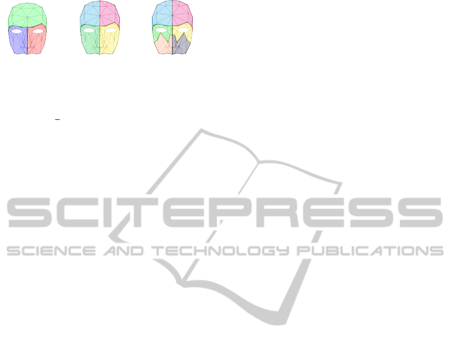
(a) (b) (c)
Figure 3: Different grouping of the face model facets used
in the tracking process. (a), (b) and (c) presents, respec-
tively, three, four and six face regions.
E
ph
T
∗
,T
0
e
x
t
=
1
N
∑
p
∗
i
∈T
∗
h
T
0
e
x
t
(
w(p
∗
i
);γ
j
,β
)
−T
∗
(
p
∗
i
)
i
2
, (8)
where p
∗
i
the i-th pixel of the j-th subregion in T
∗
and
T
0
e
x
t
(w(p
∗
i j
;γ
j
, β)) is computed as follows:
T
0
e
x
t
(w(p
∗
i
);γ
j
, β) = γ
j
T
e
x
t
(w(p
∗
i
)) + β (9)
3.2.3 Optimization
In this study, the minimization of equation 3 is
performed using the Nelder-Mead Simplex method
(Nelder and Mead, 1965; Press et al., 2007) because
of its simplicity and efficiency. The simplex is de-
fined as a convex hull with 6 + n + 1 vertices: 6 is the
number of the pose parameters, n stands for the face
region number (see figure 3) and the last parameter
corresponds to β the global illumination changes. The
Simplex algorithm is an iterative algorithm starting,
in our case, from an initial simplex defined around
b
x
t−1
. Each iteration begins by ordering the current set
of vertices according to their evaluation value com-
puted using our objective function. Then, the worst
point is discarded and several better trial points are
generated and function values are evaluated at these
points. A new simplex is then constructed using rules
that lead to the minimization of the objective func-
tion. The minimization process is stopped when the
simplex size is lower than a tolerance value or a max-
imum number of iteration is reached. The processing
rate is about 15 images per second on a standard PC
and without multi-threading programming.
4 EXPERIMENTAL EVALUATION
This section details the experiments performed to
evaluate our face pose tracking method. First, we
evaluate the accuracy of the 3D face pose estimation
in normal lighting conditions using the Biwi Kinect
Head pose database (Fanelli et al., 2011) which is
provided with ground truth data. Then, to demon-
strate the robustness of the proposed method to light-
ing variations, we have used four sequences with se-
vere lighting changes.
4.1 Evaluation on the Biwi Database
The Biwi Kinect Head Pose Database (Fanelli et al.,
2011) contains 24 sequences of 24 different persons.
In each sequence, a person rotates and translates his
face in different orientations. For each frame in the se-
quences, depth and color images are provided as well
as ground truth face poses (3 translations in mm and 3
rotation angles in degree).
The evaluation of our tracking method using the
Biwi database is done as follows. For a given se-
quence from the database, we apply our tracking
method. Then, we compare the obtained 3D face
poses to the ground truth. We define a position er-
ror (i.e., Euclidean distance between the obtained face
positions and the ground truth ones) and three rotation
errors which are the difference between the obtained
angles (i.e., yaw, pitch, and roll) and the ground truth
angles.
Table 1 shows the mean and standard deviation
of error measurements obtained for our method as
well as the methods proposed in (Fanelli et al., 2011),
(Padeleris et al., 2012) and (Rekik et al., 2013). The
second column of table 1 details the position errors
and columns 3, 4 and 5 show the estimation errors of
the rotation angles yaw, pitch and roll respectively.
From Table 1, we can see that our method is more
accurate than the methods proposed in (Fanelli et al.,
2011), (Rekik et al., 2013) and (Baltru
ˇ
saitis et al.,
2012). However, our method is as accurate as the one
proposed by Pashalis et al. (Padeleris et al., 2012) in-
sofar estimation errors presented in (Padeleris et al.,
2012) are computed from only 78% of the acquisi-
tions of the Biwi database. Indeed, all acquisitions
with location errors and rotations exceeding 10 mm
and 10
◦
, respectively, were supposed erroneous esti-
mations and ignored in the calculation of the mean
and standard deviation of the errors. We note that the
standard deviation of the errors is not provided by au-
thors in (Baltru
ˇ
saitis et al., 2012).
4.2 Robustness Evaluation in Lighting
Change Conditions
Since lighting changes in the biwi database sequences
is negligible, tracking errors presented in table 1 are
not informative about the robustness of the meth-
ods in arbitrary lighting change conditions. Conse-
quently, to evaluate the robustness of our method in
lighting change conditions, we have recorded four se-
quences from a Kinect camera for different persons in
severe lighting change conditions. To apply non-
linear lighting changes on the face, we have fixed
a light source beside the Kinect sensor and the per-
FacePoseTrackingunderArbitraryIlluminationChanges
573
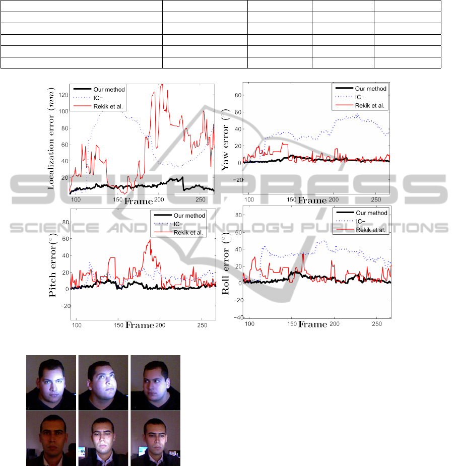
Table 1: Mean and standard deviation of the errors for the 3D face localization and the rotation angles. Errors are computed
for all sequences of the Biwi database (Fanelli et al., 2011).
Method localization (mm) yaw (
◦
) pitch (
◦
) roll (
◦
)
Fanelli et al. (Fanelli et al., 2011) 14.50 (22.10) 9.10 (13.60) 8.50 (9.90) 8.00 (8.30)
Pashalis et al. (Padeleris et al., 2012) 5.21 (2.77) 2.38 (1.80) 2.97 (2.16) 2.75 (2.09)
Tadas et al. (Baltru
ˇ
saitis et al., 2012) 7.56 ( ) 6.29 ( ) 5.10 ( ) 11.29 ( )
Rekik et al. (Rekik et al., 2013) 5.10 (3.01) 5.13 (3.33) 4.32 (2.65) 5.24 (3.43)
Our method 5.26 (3.60) 4.21 (1.43) 3.13 (2.40) 4.25 (3.67)
Figure 5: Variation of the localization and the rotation angles errors in the first sequence.
Figure 4: Examples of color images recorded from the RGB
camera of the Kinect sensor in different lighting conditions.
son is asked to move his face arbitrary in front of the
Kinect camera. Figure 4 shows some frame examples
of these sequences.
To provide ground truth to the face pose in each
frame, we fit manually the Candide face model to
the depth image and its projection to the color im-
age. Ground truths are defined by three translations
indicating the nose tip 3D position and three rotation
angles (yaw, pitch and roll) indicating the face ori-
entation. Then, we have applied our tracking method
for each sequence, and we have computed the track-
ing error by comparing the obtained 3D face poses to
the ground truth ones. Table 2 shows the mean and
standard deviation of the errors for the 3D face lo-
calization and the rotation angles. The first column
in Table 2 shows the tracking errors obtained by the
method proposed in (Rekik et al., 2013), while col-
umn two and three present the tracking errors of our
method without considering illumination change (IC-
) and with consideration of illumination change, re-
spectively. Table 2 shows that our tracking method is
more robust and accurate since other methods do not
handle illumination change in the sequences. Figure 5
shows the variation of the position and the rotation
errors obtained by applying the methods presented in
table 2 to the first sequence where ground truths are
provided only for 180 frames.
Since the number of face regions used for the
tracking is important the solve the problem of non-
linear lighting changes, we have tested our method
with different facet grouping in the face model (see
VISAPP2014-InternationalConferenceonComputerVisionTheoryandApplications
574

Table 2: Mean and standard deviation of the errors for the
3D face localization and the rotation angles. Tracking er-
rors are computed from four sequences recorded in chang-
ing and severe illumination conditions.
Method Rekik et al. IC- Our method
localization (mm) 50.50 (36.11) 59.11 (31.26) 9.50 (3.61)
yaw (
◦
) 6.90 (5.59) 33.87 (15.73) 3.17 (1.83)
pitch (
◦
) 15.78 (12.82) 12.52 (6.42) 3.32 (2.93)
roll (
◦
) 9.91 (7.22) 31.15 (11.85) 4.53 (3.32)
Table 3: Variation of the localization and orientation errors
according to the number of regions of the face.
Region number 3 regions 4 regions 6 regions
localization (mm) 9.50 (3.61) 4.40 (2.40) 3.60 (2.10)
yaw (
◦
) 3.17 (1.83) 2.36 (1.47) 1.18 (0.85)
pitch (
◦
) 3.32 (2.93) 2.87 (2.27) 3.55 (2.94)
roll (
◦
) 4.53 (3.32) 5.86 (3.14) 2.84 ( 1.87)
figure 3). Then, we have applied our method with the
different grouping. Table 3 presents the position and
the orientation errors according to the number of re-
gions of the face.
5 CONCLUSIONS
This paper presents a new approach for 3D face pose
tracking in illumination condition changes using color
and depth data from low-quality RGB-D cameras.
Our approach is based on a minimisation process
where the objective function combines photometric
and geometric energies. We have performed a quanti-
tative evaluation of the proposed method on the Biwi
Kinect Head Pose database, and we have demon-
strated the robustness of our method in case of ar-
bitrary illumination changes. Future work, will try
to ameliorate our tracking speed and will extend our
tracker to handle non-rigid facial motions by integrat-
ing the Candide facial deformation parameters in the
optimization process.
REFERENCES
Ahlberg, J. (2001). Candide-3 - an updated parameterised
face. Technical report.
Baltru
ˇ
saitis, T., Robinson, P., and Morency, L.-P. (2012). 3d
constrained local model for rigid and non-rigid facial
tracking. In IEEE CVPR, pages 2610–2617.
Ben-Hamadou, A., Soussen, C., Daul, C., Blondel, W., and
Wolf, D. (2010). Flexible projector calibration for ac-
tive stereoscopic systems. In 2010 IEEE International
Conference on Image Processing, pages 4241–4244,
Hong Kong, Hong Kong.
Ben-Hamadou, A., Soussen, C., Daul, C., Blondel, W., and
Wolf, D. (2013). Flexible calibration of structured-
light systems projecting point patterns. Computer Vi-
sion and Image Understanding, 117(10):1468–1481.
Cai, Q., Gallup, D., Zhang, C., and Zhang, Z. (2010). 3d de-
formable face tracking with a commodity depth cam-
era. In ECCV, pages 229–242.
Fanelli, G., Dantone, M., Gall, J., Fossati, A., and Van Gool,
L. (2013). Random forests for real time 3d face
analysis. International Journal of Computer Vision,
101(3):437–458.
Fanelli, G., Weise, T., Gall, J., and Gool, L. V. (2011). Real
time head pose estimation from consumer depth cam-
eras. In IEEE ICPR, pages 101–110.
Maurel, P. (2008). Shape gradients, shape warping and
medical application to facial expression analysis. PhD
thesis, Ecole Doctorale de Sciences Math
´
ematiques de
Paris Centre.
Murphy-Chutorian, E. and Trivedi, M. M. (2009). Head
pose estimation in computer vision: A survey. Pat-
tern Analysis and Machine Intelligence, IEEE Trans-
actions on, 31(4):607–626.
Nelder, J. A. and Mead, R. (1965). A simplex method
for function minimization. The computer journal,
7(4):308–313.
Padeleris, P., Zabulis, X., and Argyros, A. A. (2012). Head
pose estimation on depth data based on particle swarm
optimization. In IEEE CVPR Workshops, pages 42–
49.
Press, W. H., Teukolsky, S. A., Vetterling, W. T., and Flan-
nery, B. P. (2007). Numerical recipes: The art of sci-
entific computing. Cambridge Univ. Press, New York,
3rd edition.
Rekik, A., Ben-Hamadou, A., and Mahdi, W. (2013). 3d
face pose tracking using low quality depth cameras.
In VISAPP, pages 223–228.
Silveira, G. and Malis, E. (2007). Real-time visual tracking
under arbitrary illumination changes. In IEEE CVPR,
pages 1–6.
Smisek, J., Jancosek, M., and Pajdla, T. (2013). 3d with
kinect. In Consumer Depth Cameras for Computer
Vision, pages 3–25. Springer.
Valstar, M. F., Martinez, B., Binefa, X., and Pantic, M.
(2010). Facial point detection using boosted regres-
sion and graph models. In IEEE CVPR, pages 2729–
2736.
Yin, L., Wei, X., Longo, P., and Bhuvanesh, A. (2006). An-
alyzing facial expressions using Intensity-Variant 3D
data for human computer interaction. In IEEE ICPR,
pages 1248–1251.
Zhou, S., Chellappa, R., and Jacobs, D. (2004). Character-
ization of human faces under illumination variations
using rank, integrability, and symmetry constraints.
Computer Vision-ECCV 2004, pages 588–601.
FacePoseTrackingunderArbitraryIlluminationChanges
575
