
CoSMo: Intent-based Composition of Shader Modules
Georg Haaser, Harald Steinlechner, Michael May
Michael Schw
¨
arzler, Stefan Maierhofer and Robert Tobler
VRVis Research Center, Donau-City-Strasse 1, Vienna, Austria
Keywords:
Shader, Composition, Rendering, Language, Embedded.
Abstract:
We propose a novel shader programming model which operates on intent-oriented shader modules instead
of specific programs for dedicated GPU rasterization pipeline stages. In constrast to existing pipeline shader
frameworks, our system exposes a radically simplified pipeline, which we purposefully aligned with our basic
intuition of shaders as per-primitive and per-pixel operations and compositions thereof. This simplicity lends
itself to structure modules purely based on their intent, instead of dealing with structure enforced by specific
versions of graphics APIs. Consequently, this offers great flexibility when it comes to reusing and combining
modules with completely different semantics, or when targeting different graphics APIs. The simplicity and
uniformity of our system also motivates automatic parameterization and simplification of shader programs as
well as interesting interactive shader development and management techniques.
1 INTRODUCTION
Programming shaders for hardware-accelerated ras-
terization frameworks like DirectX or OpenGL has
attained an important role in the development pro-
cess of rendering applications. Even though the
flexibility and possibilities in graphics development
have drastically improved with the introduction of
these shaders over the last few years, recent advances
in “CPU-based” programming languages and soft-
ware engineering are often not reflected in shader-
programming. Especially the limitations in terms of
shader management in larger software projects cause
the tasks of combining shader effects, targeting dif-
ferent hardware, supporting older API versions or
optimizing these shader permutations to become ex-
tremely time-consuming, tiresome, and error-prone.
The C-style definition of a single shader stage pro-
gram is only simple during the primary creation pro-
cess: As soon as such an effect has to be combined
with other shaders to generate the desired final surface
illumination, or has to be used on another API version
or target platform, programmers either tend to build
large, complex
¨
Uber-Shader constructs with computa-
tionally expensive dynamic branching techniques, or
manage hundreds of shader combinations and permu-
tations manually. Object-oriented approaches (Mc-
Cool et al., 2002; Kuck and Wesche, 2009; Foley
and Hanrahan, 2011) and novel Shader Model 5 func-
tionality (e.g. interfaces (Microsoft, 2010)) ex-
tend procedural languages with abstractions like in-
terfaces and limit code duplication via inheritance. In-
heritance as mechanism for composition however has
shortcomings in terms of ad hoc compositions and re-
usability, as each composition has to be stated explic-
itly (see sections 2.1 and 2.2) and in terms of exten-
sibility, as extension points have to be anticipated by
providing abstract or virtual methods.
Based on these observations, we propose a novel
shader programming model that emphasizes the intent
of a shader, based on the following ideas:
• abstract shader stages: by freeing the shader
modules from concrete pipeline stages, we let
the programmer specify what he wants his
shader modules to do in an abstract, backend-
independent manner
• composition via semantic input/output types: with
the introduction of semantically annotated input
and output types, these types encode the intent
of what is computed by each shader module, and
thus composition operators can be built, that com-
bine the modules according to this intent
• fine-tuning of semantics: by providing more de-
tailed information for the semantic types such as
computation rates, the programmer can exactly
specify the intent of his shader
Using these ideas to provide a system that au-
189
Haaser G., Steinlechner H., May M., Schwärzler M., Maierhofer S. and Tobler R..
CoSMo: Intent-based Composition of Shader Modules.
DOI: 10.5220/0004687201890199
In Proceedings of the 9th International Conference on Computer Graphics Theory and Applications (GRAPP-2014), pages 189-199
ISBN: 978-989-758-002-4
Copyright
c
2014 SCITEPRESS (Science and Technology Publications, Lda.)

Figure 1: Example built with composed shader modules (from left to right): transformation and per-pixel lighting, transfor-
mation and texturing, transformation/normal mapping/texturing and lighting, transformation/normal mapping/texturing/point
sprite generation and lighting, transformation/normal mapping/texturing/point sprites/thick line generation and lighting.
tomatically combines modules based on their intent,
we overcome the combinatorial explosion of typical
shader systems where each and every combination
has to be specified explicitly: Modules are typically
expressed only in their most general form, and can
be composed either statically as hard-coded expres-
sions, or programmatically, which is useful to gener-
ate shaders based on runtime information or whole
families of related shaders. Our high-level shader-
code requires a specific functionality to be defined
only once—no matter how often it is combined with
other shaders and on how many target platforms it
is deployed—while unneeded calculations are auto-
matically eliminated. We leave the error-prone task
of finding the optimal shader stage for each com-
putation to the machine, which automatically maps
shaders onto specific pipeline architectures (e.g. Di-
rectX), performs global and local optimizations and
code generation for distinct shader permutations, and
finally emits a low-level shader program (e.g. HLSL)
comparable to hand-crafted code.
2 BACKGROUND
The ancestors of today’s shading languages are
Cook’s shade trees (Cook, 1984) and Perlin’s image
synthesizer (Perlin, 1985). Cook’s shade trees clas-
sify independent aspects like lighting, surface and
volume into separate modules called shading pro-
cesses. As a mechanism for composition each process
is represented as an expression tree which supports
grafting of commonly used expressions into other
processes. However, the underlying model of compu-
tation which is purely declarative allows for no con-
ditional control flow like loops as well as no mutable
state. Perlin’s image synthesizer is based on impera-
tive procedures and therefore dissolves these limita-
tions, but abandons the idea of logically independent
shading processes. Procedures work on streams of
fragments, and describe shading computations after
hidden surface removal.
The most prevalent shader languages for real-time
rendering (Cg (Mark et al., 2003), HLSL (Microsoft,
2012), and GLSL (Kessenich et al., 2012)) follow
the shader-per-stage approach. Similarly to Perlin’s
image synthesizer each stage works on streams of
objects like vertices, primitives or fragments. As a
consequence they directly reflect the various pipeline
stages of the hardware in the language itself. Al-
though there are little restrictions in terms of algo-
rithms that can be formulated, a corresponding shader
function must be provided for each of the stages.
2.1 Towards Composability
Shader languages like HLSL provide procedures as
their main structuring mechanism.
¨
Uber-Shaders usu-
ally implement the sum of all desired features and use
ad-hoc mechanisms like macros and plain text pro-
cessing for specialization and feature selection.
Metaprogramming frameworks (McCool et al.,
2002; McCool and Toit, 2004; McGuire, 2005; Kuck
and Wesche, 2009) overcome the lack of language
level abstractions by utilizing meta-programming and
macros. LibSh (McCool et al., 2002) provides an em-
bedded language in C++, utilizing its features like ob-
jects and templates for combining shaders. McCool et
al. (McCool et al., 2004) extends LibSh with algebraic
combinators connection and combination which pro-
vides an expressive basis for combining shader func-
tions.
Elliot (Elliott, 2004) proposes Vertigo, an em-
bedded domain specific language written in Haskell
that provides combinators in a very natural way.
Based on these combinators, an implementation of
a sophisticated shading infrastructure comparable to
RenderMan Shading Language (RSL) (Hanrahan and
Lawson, 1990) is demonstrated, including a subse-
quent compilation process which creates vertex- and
fragment-shader programs.
Abstract shade trees (McGuire et al., 2006) are
GRAPP2014-InternationalConferenceonComputerGraphicsTheoryandApplications
190

based on a visual programming approach for shaders,
and also provide automatic linkage of shader param-
eters as well as semantic operations like vector ba-
sis conversion. Although different shader components
compose well, geometry shaders and tessellation are
not treated at all. Trapp et al. (Trapp and D
¨
ollner,
2007) structures GLSL shader code into code frag-
ments, each typed with predefined semantics. Code
fragments may be composed at run-time and com-
piled to
¨
Uber-Shaders. Of course
¨
Uber-Shaders suffer
from bad performance. Like other metaprogramming
approaches the system cannot provide proper seman-
tic analysis and cross-fragment optimization.
2.2 Towards Pipeline Shaders
The RenderMan Shading Language by Hanrahan and
Lawson (Hanrahan and Lawson, 1990) combines the
expressiveness of Perlin’s image synthesizer with in-
dependent shader processes introduced by Cook. The
concept resembles object-oriented classes, whereby
each virtual method corresponds to an entry point
called by the render system. Subclasses like surface,
light and volume may be attached to surfaces. Fur-
thermore RSL extends the concept with computation
rates, i.e. the notion of inputs varying two different
rates: uniform and varying. Specialized control-
flow constructs provide mechanisms for communica-
tion between shaders.
A further refinement for computation rates was
introduced by Proudfoot et al. (Proudfoot et al.,
2001) in their Stanford Real-Time Shading Language
(RTSL): constant, primitive group, vertex and
fragment, where the last two rates directly corre-
sponded to the stages of early programmable GPUs.
Like Cook’s shade trees (Cook, 1984), RTSL pro-
grams are purely declarative and can therefore be rep-
resented as DAGs, which affects expressiveness (e.g.
limited data dependent control flow).
Renaissance (Austin, 2005) takes a more gen-
eral approach and represents different shader pipeline
stages as single functional shader programs. Parame-
ters implicitly correspond to different computations
rates. Compilation automatically lifts expressions
into the earliest possible pipeline stage while main-
taining semantics. However, Renaissance lacks sup-
port for structuring monolithic shader programs into
well defined reusable modules, and no semantics for
lifting expressions to groupwise shader stages (e.g.
geometry shaders) are presented.
Foley and Hanrahan introduce Spark (Foley and
Hanrahan, 2011), a pipeline shader approach based
on RTSL (Proudfoot et al., 2001). Its two-layer ap-
proach uses declarative shader graphs on top of pro-
cedural subroutines and therefore combines the ap-
proaches of Cook (Cook, 1984) and Perlin (Perlin,
1985). Spark expands RSL’s idea of treating a shader
in an object-oriented way by using extending, virtual-,
and abstract identifiers for compositing and customiz-
ing shaders. Rate-qualifiers and conversions between
different rates are extensible and thus defined individ-
ually by each supported pipeline. Different modules
may be composed by using mixin inheritance. Like
other
¨
Uber-Shader approaches before, Spark does not
solve the combinatorial explosion problem because
each composition must be stated explicitly.
3 DESIGN
3.1 A Shader as a Pixel-valued Function
Shader programming targets a highly parallel execu-
tion environment, where shading can be performed
independently for each surface point, therefore func-
tional programming is a natural match for specifying
shaders (Cook, 1984). Although parts of a shader can
be programmed in procedural style using local vari-
ables and loops, a complete shader program only has
a single output value—the target pixel—and can thus
be viewed as a single function. By using tail recur-
sion instead of loops, and higher-order functions for
control-flow it is even possible to map any procedural
shader program to a purely functional representation.
Rennaissance (Austin, 2005) is an example of such a
functional approach to shader programming.
Since the output value of a shader expression for
a single pixel can be an aggregate of multiple simple
values (e.g. it can contain a colour, a depth value,
etc.), we use the term shader module to denote a
shader function with multiple input and output values.
Multiple output values are programmatically handled
by returning a single structure containing the individ-
ual output values.
Although our approach is based on the compo-
sition of such shader modules, and thus retains the
expressiveness and extensibility of a functional de-
sign (which goes beyond what is possible with the
specialised control flow elements introduced in RSL
(Hanrahan and Lawson, 1990)), we have included
control flow functions that are modelled on impera-
tive languages in order to cater to shader programmers
that are used to imperative shader languages. Details
on these control flow functions are given in Section 4.
CoSMo:Intent-basedCompositionofShaderModules
191
3.2 Semantic Composition of Shader
Modules
Combining shaders modules that are formulated as
expressions can be done in a pipeline approach, by
routing the output of one component into the input of
another component. In order to derive the necessary
composition functions for combining shader mod-
ules we will look at a simple example that combines
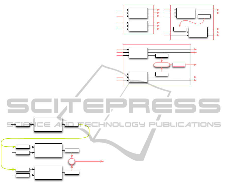
three shader modules with two composition operators,
namely Sequence and Combine(operator) that are ap-
plied to the individual output fields (see Figure 2).
Note, that the different composition operators need to
be applied to different types of input and output (Nor-
mal, Color, LightPos). We use the term semantic for
these types, as they go beyond the typical notion of
data types in a language: both Normal and LightPos
are represented as float vectors, but this does not cap-
ture their intent.
Diffuse
Illumina,on
Shader2Module
Bump6Map
Shader2Module
Specular
Illumina,on
Shader2Module
Normal
Normal
LightPos
Normal
Color
Normal
LightPos
Color
+
Sequence
Combine
Figure 2: The output values of three simple shaders can be
combined with two composition operators: Sequence and
Combine(operator +).
Generalizing from this example, we define the fol-
lowing three basic composition operators for semantic
shader composition, that operate on arbitrary shader
modules each with one or more semantic input types
and one or more semantic output types (see Figure 3):
Compose(module
1
, module
2
) composes the output
of the two shader modules. All output semantics
of the two input shader modules must be different.
Sequence(module
1
, module
2
, {semantic
1
, ..., semantic
M
})
combines the specified semantics of the supplied
shader modules in sequence. The remaining
output semantics of the two input shaders must
be different.
Combine(module
1
, module
2
, semantic, operator)
applies the supplied binary operator to the output
of the two input shaders with the given semantic
to return a value of the same semantic. The
shader
module
₂
seman-c
shader
module
₁
seman-c
shader
module
₂
seman-c
operator
Compose
Combine
Sequence
seman-c
shader
module
₁
seman-c
shader
module
₁
shader
module
₂
Figure 3: The three semantic-aware basic composition op-
erators for shader composition. For illustration purposes,
the Sequence function is depicted with only one semantic
routed between its shader module arguments.
remaining output semantics of the two input
shader modules must be different.
For all composition operators, the input semantics
of the two input shader modules are allowed to be ei-
ther partially or completely equal. In this case, the
same value is supplied to both shaders. These basic
composition operators add the concept of semantic-
specific operations to the usual composition functions
used in functional languages. On top of these basic
composition operators we can now define a more gen-
eral composition function that sequences, combines,
and composes multiple shader modules based on their
semantic:
Composition(module
1
, module
2
, . . . module
N
,
semantic
1
: composition
1
,
.
.
.
.
.
.
semantic
M
: composition
M
,
de f ault : composition
de f ault
)
where a separate composition operator (either
Sequence or Combine(operator)) is specified to com-
bine each semantic and Compose is wrapped around
the result.
We provide a number of convenience composi-
tions in our approach, that are specializations of this
general composition function with various predefined
function and operator arguments. For convenience we
also predefine simple shaders for changing semantics
(e.g. Position → Color). An example composition
can be found in Section 5.
Our approach of automatically combining shaders
based on their semantically tagged inputs and out-
GRAPP2014-InternationalConferenceonComputerGraphicsTheoryandApplications
192
puts is inherently more flexible than a static object-
oriented approach as implemented by Spark (Foley
and Hanrahan, 2011):
• The object-oriented way of extending functional-
ity by overriding virtual functions requires, that
each possible extension point needs to be foreseen
by the implementer of the base shaders. Since
only a limited number of possible ways of extend-
ing functionality can be provided in a typical de-
sign of such base shaders, the extensibility of such
an object-oriented approach is necessarily limited.
• Due to the static way of combining and extending
shaders, each and every new combination of sim-
ple shader functions must be explicitly and man-
ually implemented. Since the number of com-
binations of simple shaders is exponential in the
number of shaders, this leads to a combinatorial
explosion that cannot be handled by a static ap-
proach. The use of a composition function as
shown above, makes it possible to automatically
combine simple shaders based on the geometry
that needs to be rendered: the rendering frame-
work can analyse the properties of the geometry,
and combine only the simple shaders that are ac-
tually needed for rendering the combination of
properties encountered.
All composition possibilities offered by a static
object-oriented approach can be easily built using a
sub-set of the available functionality in our meta-
function approach:
• Each virtual method corresponds to a semantic
tag: different simple shaders can perform differ-
ent operations on the input with the same seman-
tic tag. Changing the implementation of one vir-
tual method thus corresponds to replacing one of
the simple shaders in a composition of multiple
shaders.
• The effect inheritance in the object-oriented ap-
proach can be realised using the combine com-
position operator on two simple shaders that cor-
respond to the base-class implementation and the
overriding implementation. By using a function
that ignores the result of the simple shader corre-
sponding to the base-class the result of the combi-
nation corresponds to the result of the overriding
simple shader.
Thus our approach provides a superset of the func-
tionality provided by the object-oriented approach,
and the additional functionality eliminates the large
number of shader combinations that have to be man-
ually specified.
3.3 Abstract Stages
The various stages in the shader pipeline can be
viewed as optimizations on the single pixel-value
function, in order to reduce the number of evaluations
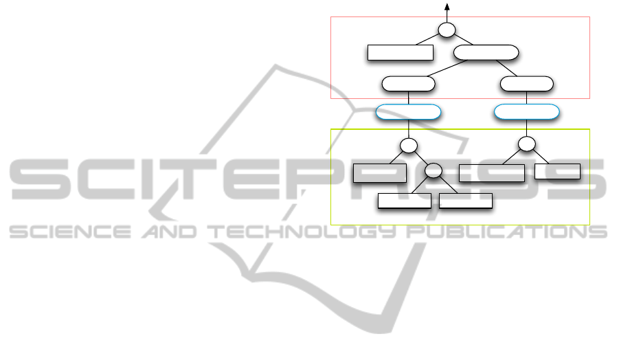
of various expressions (for an example see Figure 4).
per$pixel$opera*ons
ViewTrafo
*
LightPos Posi1on
Normalize
(ViewTrafo88)
*
Normal
Normalize
DotProductDiffuseColor
*
–
Interpola*on
Interpola*on
-1
T
per$primi*ve$opera*ons
Figure 4: Optimizing the evaluation of a shader expression
by evaluating the parts at different stages. The indicated in-
terpolation functionality is provided by the hardware stages.
Although in principle, every shader could be for-
mulated as a single function that returns a pixel value,
this would require the implicit interpolation that is
performed between the vertex and fragment stages
of the shader pipeline (see Figure 4) to be explic-
itly specified in this function. In order to overcome
this inconvenience, we propose to retain the notion
of shader stages, but as opposed to the multiple hard-
ware stages we only specify two abstract stages, that
turn out to be sufficient in practice :
per-pixel operations :
also called per-fragment operations, these are all
the operations that need to be performed for each
pixel or fragment. Typically this includes all tra-
ditional shading operations that affect the material
of an object. In functional notation, these opera-
tions perform the mapping: per pixel parameters
→ per pixel output.
per-primitive operations :
all operations performed for each primitive (e.g.
triangle or line). This typically encompasses ge-
ometric transformations. In functional notation,
these operations perform the following mapping:
per primitive parameters → per primitive output.
Thus all the simple shaders that can be composed
in our framework consist of explicitly specified per-
pixel and/or per-primitive operations, and thus each
of our simple shaders can be viewed as either a partial
CoSMo:Intent-basedCompositionofShaderModules
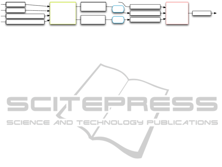
193

or a fully specified, but still abstract pipeline of oper-
ations (see Figure 5). Since we do not explicitly spec-
ify operations for a specific hardware pipeline, all our
shaders are still specified in an abstract manner, and
need to be explicitly mapped onto the hardware stages
of a concrete pipeline.
This has some consequences for the composition
operators defined in the previous section: specifically,
a per-pixel output of a shader module cannot serve
as an input for a per-primitive shader module. If
each shader module that consisted of a per-geometry
stage and a per-pixel stage was viewed as a monolithic
block with no allowed change in the routing of data
between the per-geometry and the per-pixel stage, this
would lead to significant limitations on which shader-
modules could be combined.
In order to avoid that, we combine the stages of
our shader modules individually, i.e. the composition
works independently on the per-primitive stage and
on the per-pixel stage. This makes it possible to com-
bine shader modules as simply as if they were single
stage modules, and retain the intended functionality
programmed in the different stages. The semantically
tagged inputs and output of the individual stages are
available for automatic composition with other shader
modules (see Figure 5).
Thus we extend our concept of shader modules
to encompass whole shader pipelines, on which our
composition operators work, retaining the semantic
input and output types between the abstract stages,
which is beyond the functionality of the algebraic
combinators of McCool et al. (McCool et al., 2004).
3.4 Optimization
Na
¨
ıvely mapping such high-level shaders onto the
hardware stages of a concrete pipeline such as the Di-
rectX 11 pipeline results in a lot of overhead due to
a number of possible inefficiencies. In order to pro-
vide comparable performance in our system, we per-
form several optimisations highlighted in the follow-
ing section.
Dead code elimination. Since our modules are pro-
grammed to be maximally reusable, they are imple-
mented to cover the most general case, and thus pro-
vide a large number of semantic outputs which can be
used by other modules that are placed later in a com-
position. Thus it is of vital importance for the overall
performance to identify all unused outputs, and elim-
inate these from the composition result: this is done
by starting with all used pixel outputs and tracking all
necessary inputs back through the pipeline. All un-
used inputs and outputs are removed, essentially per-
forming a dead code elimination step.
Backend stage mapping. A typical hardware shader
pipeline has a number of stages that can be used
to perform the operations in our pipelined shaders.
Based on the abstract stage, the following optimisa-
tion steps are performed:
per-primitive operations :
Since the current (DirectX 11) backend basi-
cally offers three stages for geometry processing
(vertex shader, tesselation shader, and geometry
shader) with different capabilities and associated
computation rates our composed modules need to
be mapped onto these efficiently. Since the com-
putation rates for these hardware-stages are gen-
erally unknown (we don’t know what our inputs
will look like) we decided to move all operations
to the earliest stage possible, with the underlying
assumption, that each operation is thus performed
at the lowest rate. It is, for example, possible
to move geometry shader operations, which are
equally performed for all vertices, to the vertex
shader. Similar rules can be derived for the other
hardware-stages, an overview of these rules can
be found in Section 4. A number of additional
limitations (due to hardware capabilities) are in-
troduced, e.g, the tessellation-shader needs to be
done prior to a geometry-shader, etc.
per-pixel operations :
pixel or fragment-shaders are divided into two
parts: the first part represents calculations invari-
ant respective to rasterizer-interpolation, which
can therefore be performed per primitive (in gen-
eral the faster solution). The second part con-
sists of all operations that can only be performed
in a pixel shader. This splitting may cause addi-
tional traffic for the rasterizer-interpolation since
this may need e.g. the interpolation of a vector
instead of a scalar. Since these costs are hard to
estimate we move only operations where the in-
terpolated type does not exceed the result type in
size.
Shader module specialization. Since a single gener-
ated shader module might still cover a number of dif-
ferent input-setups (textured vs. non-textured, etc.)
using shader-control-flow we provide methods for
simply specialising a shader module using contextual
information (e.g. there are no textures available, etc.)
The shader modules are then partially evaluated using
this information and recompiled for the backend. If,
for example, a geometry does not contain normals the
corresponding shader modules are optimised to elim-
GRAPP2014-InternationalConferenceonComputerGraphicsTheoryandApplications
194
ViewTrafo
LightPos
GlobalPrimi4veNormal
GlobalPrimi4vePosi4on
DiffusePixelColor
LocalPixelLightDir
LocalPixelNormal
PixelColor
LocalPrimi4ve
LightDir
LocalPrimi4ve
Normal
per$primi've
opera'ons
per$pixel
opera'ons
Inter&
pola+on
Inter&
pola+on
Figure 5: A simple shader module consists of explicitly specified per-primitive and per-pixel operations each with their
semantic inputs and outputs. This shows the example from figure 4 tagged with semantic inputs and outputs.
inate any code that accesses normals of the geometry,
thereby improving rendering performance.
Shader module unification. Since shaders are compo-
sitions of abstract modules it’s relatively easy to find
common operations for them using the high level in-
formation provided by the composition operators. If
the rendering performance can be improved by reduc-
ing switches between shaders, two shader modules
can be unified using simple control flow, adding a pa-
rameter to select the shader module as an additional
input to the combined shader module.
Common subexpression elimination. Although com-
mon subexpression elimination results in optimal
code respective to the number of operations, ad-
ditional temporary variables stressing the HLSL-
compiler need to be introduced. In optimizing
compilers, sophisticated analysis carefully choose
subexpressions to be considered for code motion
(e.g. (Knoop et al., 1992)) in order to limit tempo-
raries. Our system in contrast heuristically elimi-
nates expressions exceeding a syntactic complexity
threshold. These complexities are based on estimated
complexities for all intrinsic functions which are sim-
ply summed for each expression. With this simple
scheme the HLSL-compiler does a good job in opti-
mizing shaders while maintaining good compile-time
performance.
Constant/Uniform-calculations. All computations re-
sulting in a constant value (for each draw call) can
be pre-calculated by the rendering system. Since a
brute force approach would result in a large number
of uniform-parameters only calculations exceeding a
certain complexity (as mentioned above) are consid-
ered.
Arithmetic optimizations. Since there are only very
few restrictions on how to compose shaders (i.e. out-
puts and inputs must match), it is possible to in-
troduce unnecessary calculations through these com-
positions (e.g. normalize(normalize(vector)),
(a − a), etc.). Similarly to tree parsers (Fraser
et al., 1992), used for instruction selection in code
generators our optimizer maintains a set of expres-
sion patterns with associated rewrite rules and some
estimated cost. Notably, our system also consid-
ers domain-specific knowledge as a variables vector-
basis for further optimization. As an example,
ViewMatrix*ModelMatrix is transformed to use the
uniform ModelViewMatrix in order to eliminate ex-
pensive matrix multiplications.
User guided simplification. Additional contextual in-
formation can be specified for shader inputs values.
As an example, the user may annotate the vertex col-
ors to be constant or the normals to be constant per
face.
Using these annotations the backend stage map-
ping can perform further optimisations by moving op-
erations to earlier stages. Together with redundancy
removal, dead code elimination, and constant/uniform
calculations this can lead to significantly simplified
shaders. As an example, it is unnecessary to interpo-
late face normals in a shader, when the normals are
known to be constant per primitive.
Further optimization possibilities. Our abstract
pipeline representation is general enough to support
completely different approaches like perceptual sim-
plification methods (Sitthi-Amorn et al., 2011), or
automatic approaches exploiting temporal coherence
(Sitthi-Amorn et al., 2008), which we will pursue in
the future.
4 IMPLEMENTATION
Our shading language is implemented as an extension
of an existing in-house rendering framework written
in C#. Of course it is possible to implement our ex-
pression tree based approach with any language that
provides abstract data types, the use of anonymous
functions significantly reduces the syntactic overhead.
A C++ 11 implementation would be equivalent to
our approach, while a Java implementation would use
anonymous classes instead of anonymous functions.
The expression trees in our approach are created
and combined using so called shader types, which
represent predefined data types available to shaders
(e.g. vectors, matrices, textures, aso.). Each shader
CoSMo:Intent-basedCompositionofShaderModules
195
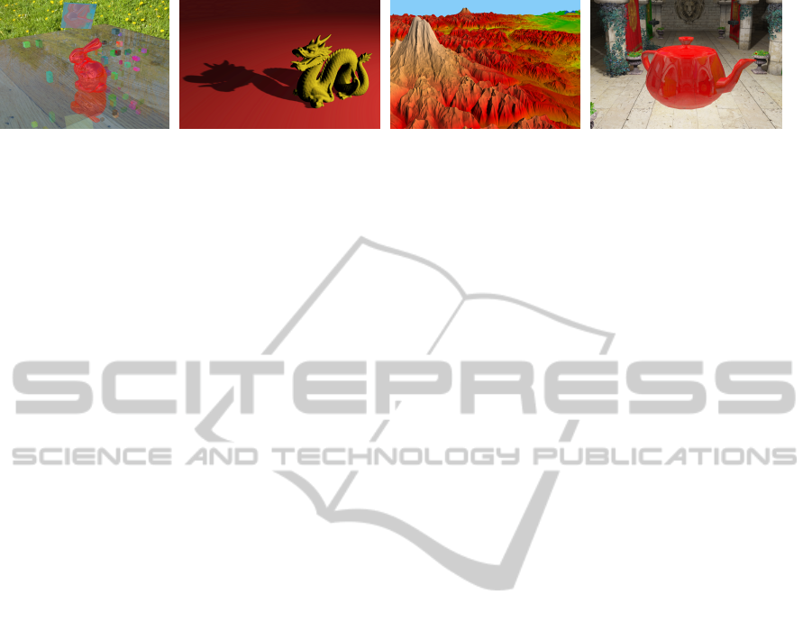
Figure 6: Shader effects composed with our approach. From left to right: raytraced reflections with simple texturing, a
composition of an illumination and shadow mapping shader, and a subsivision shader (all from section 5), as well as a screen-
shot from our lighting design application (see Section 6.1) demonstrating texturing and reflective materials with environment
mapping.
type provides methods (e.g. the operators + and – or
the dot product) that do not actually perform opera-
tions, but build an expression tree for the correspond-
ing operations. Thus each expression that specifies a
shader module, returns the complete expression tree
for that shader module upon execution.
Due to the flexibility of our functional-style imple-
mentation we are not limited to predefined control
flow statements such as the RenderMan Shading Lan-
guage (RSL) (Hanrahan and Lawson, 1990) : we pro-
vide higher-order functions that encapsulate condi-
tional evaluation and loops. This makes it possible to
integrate conditions and loops into expression trees in
typical implementation languages of rendering frame-
works, even if it is not possible to overload intrinsic
language constructs such as the conditional evaluation
operator condition ? value
1
: value
2
and the for loop
for shader types:
var floatVal = Fun.IfThenElse<Float>(c < 1.0f, c, 1.0f);
var initial = new { Index = Int.Zero, Val = Float.Zero };
var diffuse = Fun.Loop(initial, i => i.Index < lightCount,
i => {
var dir = light[i.Index] - worldPosition.XYZ;
return new { Index = i.Index + 1,
Val = i.Val + normal.Dot(dir.Normalized) };
});
Figure 7: Example usage of higher-order functions for
loops and conditional execution.
As mentioned in Section 3.4, the evaluation of each
expression is moved to the earliest possible stage in
any given hardware pipeline. In the following list
we give the conditions for performing the indicated
optimizations:
PixelShader → GeometryShader : An expression
can be moved, if it comprises a linear function.
Note that functions can be linear under specific
circumstances, e.g. if one function argument is a
constant.
GeometryShader → DomainShader/VertexShader
: If the same function is applied to all vertex-
dependent inputs (i.e. it appears for each of
the vertices), the function-expression with its
arguments can be moved.
DomainShader → HullShader : If an expression
does not contain the tessellation coordinate (i.e.
the domain location) it can be moved.
DomainShader → HullShaderConstantFunction
Similar to DomainShader → HullShader.
HullShader → VertexShader : Identical pre-
conditions to GeometryShader → VertexShader
stage.
Although we focussed on the Rules for DirectX 11
and OpenGL 4 we also implemented an experimen-
tal backend for our OpenCL based raytracer, which
only supports one shader-stage computing the color
for a primitive at a certain coordinate. Due to our ab-
stract stage interpretation the modules could easily be
mapped onto this stage when possible (features like
tessellation are currently not supported by the ray-
tracer)
The first step of the compilation process is the cre-
ation of a single pipeline for the completely combined
shader modules. This abstract pipeline is then pro-
cessed using the optimisation stages shown in Section
3.4. The output of the optimisation process is a com-
plete hardware shader in the shading language of the
backend: in our case a complete HLSL shader for the
DirectX 11 backend.
5 EXAMPLES
In order to demonstrate the applicability of our ap-
proach to common techniques, we provide code ex-
cerpts for per-pixel lighting, shadow mapping and
subdivision (see Figure 6). Furthermore, we demon-
strate the interactive capabilities of our system in the
accompanying video.
The following example shows the full implemen-
tation of a basic transformation pipeline with per-
pixel lighting. Note that user-defined parameters are
GRAPP2014-InternationalConferenceonComputerGraphicsTheoryandApplications
196

communicated by name (e.g. "LightPosition"),
and vertices of primitives supplied to the primi-
tive shader can be accessed using iterators (e.g.
.DoByVertex). We also provide swizzle operators
(e.g. .XYZ) including constants (letter O is zero, letter
I is one) for all vector types.
public class PerPixelLighting : Module {
public class Vertex {
public Float4 Position = Varying.Position;
public Float3 Normal = Varying.Normal;
public Float4 WorldPosition = Varying.WorldPosition;
public Float4 Color = Varying.Color;
}
public class Pixel {
public Float4 Color = Varying.Color;
public Pixel(Float3 color, Float alpha = 1) {
Color = new Float4(color, alpha);
}
}
public Fragment<Pixel> Shader(AnyPrimitive<Vertex> input) {
var transformed = input.DoByVertex(v => {
v.Position = Uniform.ModelViewProjTrafo * v.Position;
v.Normal = Uniform.NormalTrafo * v.Normal;
v.WorldPosition = Uniform.ModelTrafo * v.Position;
return v;
});
return transformed.Rasterize(f => {
var dir = (Uniform.LightPositions[0]
- f.WorldPosition).XYZ.Normalized;
return new Pixel(dir.Dot(f.Normal.Normalized) * f.Color.XYZ,
f.Color.W);
});
}
}
Figure 8: Vertex transformation and per pixel lighting ex-
ample.
Geometry vertex colors are automatically bound
to the Varying.Color input if needed.
Here we demonstrate the composability of mod-
ules by combining per-pixel lighting from Figure 8
with a simple shadow mapping module.
public class ShadowMapping : Module {
public Float4x4 ShadowMapTrafo;
public Texture2D ShadowMap;
private Float3 GetShadowTexCoord(Float4 worldPos) {
var p = ShadowMapTrafo * worldPos; var pp = p.XYZ / p.W;
var tc = new Float3((Float2.II + pp.XY) * 0.5f, pp.Z);
tc.Y = 1 - tc.Y; return tc;
}
public Fragment<Pixel> Shader(AnyPrimitive<Vertex> input) {
return input.Rasterize(f => {
var mytc = GetShadowTexCoord(f.WorldPosition);
var smValue = ShadowMap.SampleCmp(mytc.XY, mytc.Z);
return new Pixel(f.Color.XYZ * smValue, f.Color.W);
});
}}
Figure 9: Shadow-mapping example.
Both modules can be simply composed in the fol-
lowing way:
...
var sg = ... // some scene graph node
var shadowMapping = new ShadowMapping();
var surface = Composition.Sequence.Compose(new PerPixelLighting(),
shadowMapping);
shadowSurface.ShadowMap = renderTarget.DepthTexture;
shadowSurface.ShadowMapTrafo = ... // the transformation value
sg = sg.Surface(surface);
...
Figure 10: Composition of lighting and shadow mapping.
The code shown in Figure 10 assigns values to
module inputs by implicitly creating uniform inputs
in the backend code and setting their values using
the renderer infrastructure. These values can thus be
changed at runtime.
public Float GetFactor(Float4 p0, Float4 p1) {
var len = (p1.XYZ - p0.XYZ).Length;
return Float.Clamp(len / MaxLineLength, 1, 64);
}
public Triangle<Vertex> Shader(Triangle<Vertex> input) {
return input.DoByPrimitive( tri => {
var f0 = GetFactor(tri.P1.Position, tri.P2.Position);
var f1 = GetFactor(tri.P2.Position, tri.P0.Position);
var f2 = GetFactor(tri.P0.Position, tri.P1.Position);
var factors = new TessellationFactors();
// tessellation is defined as in OpenGL 4/DirectX 11
factors.EdgeFactors = new[] { f0, f1, f2 };
factors.InnerFactors[0] = (f0 + f1 + f2) / 3.0f;
return factors;
},
(tri, constant, crd) => return new Vertex() {
Position = Float4.Lerp(
tri.P0.Position, tri.P1.Position, tri.P2.Position,
crd)
});
}
Figure 11: Simple tessellation example.
Figure 11 shows a simple subdivision operation
mapped to the DirectX 11 tessellation stages. The first
anonymous function which calculates the tessellation
factors can return any custom type inheriting from
TessellationFactors. The constant argument in
the interpolation function then refers to that type. Al-
though it would theoretically be possible to create ar-
bitrary output triangles for a given input patch using
the DirectX/OpenGl tessellation stages we decided
to expose the functionality as provided by our main
backend. The first lambda function basically corre-
sponds to the Hull-/TessellationControl-Shader and
the second to the Domain-/TessellationEvaluation-
Shader.
6 ANALYSIS
6.1 A Real-world Comparison
We evaluated our concept by re-implementing all
shaders used in a production-quality real-world appli-
cation for lighting design: it uses shaders for comput-
ing global illumination, for drawing lines and points
CoSMo:Intent-basedCompositionofShaderModules
197

in debugging and editing views, and for rendering a
number of different materials with diffuse, and spec-
ular components and environment maps for realistic
looking reflections. The complexity of shaders ranges
from simple flat-shading all the way to a global-
illumination shader that needs to perform polygon
clipping for each rendered pixel (see Figure 6 as well
as the demonstration in the accompanying video).
The following table gives an overview of the number
of shader modules and the lines of code for the same
functionality using standard HLSL and our composed
shader modules (CoSMo).
Table 1: Code metrics for a real-world lighting design ap-
plication.
lines # modules compile time
HLSL 2324 37 7.5s
CoSMo 1148 20 11.8s
We were able to roughly halve the number of
code-lines as well as the number of modules, while
maintaining comparable shader-compile-times and
shader performance. Due to the high level of reuse
enabled by our shader modules, the shader modules
implemented for this application are a lot less specific,
and can therefore be reused in a number of future ap-
plications.
6.2 Performance
We evaluated CoSMo performance using three sam-
ple shaders:
skinning: renders two animated simple meshes repli-
cated 50 times without hardware instancing with
standard skinning and diffuse lighting, where
skinning is performed with a maximum of four
bone influences per vertex.
tesselation: subdivides all 871414 triangles of the
Stanford dragon to 1-pixel-sized triangles using
simple interpolation of positions, normals and
light direction, and applies diffuse lighting.
shadow mapping: renders a shadow mapped Stan-
dard dragon using a pre-calculated shadow map.
A 9x9 Gaussian filter implemented in the pixel
shader is used to blur the shadow.
All our tests were performed on an Intel(R)
Core(TM) i7 CPU 930 @ 2.80 GHz system with 12
GB of RAM and a GeForce GTX 480 graphics card.
In our first evaluation (see Table 2) we compared
the final rendering speed of manually coded shaders
with CoSMo-generated shaders. We found that in
most cases CoSMo produced equally fast or faster
shader code. We rely on the aggressive optimizations
in the compiler backend (HLSL or GLSL) to over-
come some of the deficiencies in our code genera-
tor. The tessellation example was slightly faster since
some calculations performed in the DomainShader
were automatically moved to the vertex shader.
Table 2: Performance results in frames per second (fps)
comparing CoSMo generated shaders with manually coded
shaders.
shader manual CoSMo factor
skinning 35 fps 35 fps 1.00
tesselation 178 fps 189 fps 1.06
shadow-mapping 209 fps 209 fps 1.00
Our second evaluation (see Table 3) shows the
compile times for manually coded shaders compared
to the sum of code generation and compile times for
CoSMo shaders. The additional generation of HLSL
from CoSMo code results in compile-times that are
less than 2 times longer for the given examples, an ac-
ceptable overhead given the increased flexibility and
reusability.
Table 3: Compile times in milliseconds (ms) of manually
written HLSL code and CoSMo code. The CoSMo com-
pile times are given as the sum of generation of HLSL from
CoSMo and the HLSL compile time.
shader manual CoSMo factor
skinning 140 ms 217 ms (78+139) 1.54
tessellation 46 ms 81 ms (33+48) 1.77
shadow-map 85 ms 110 ms (24+86) 1.30
7 CONCLUSIONS AND FUTURE
WORK
We have demonstrated a powerful framework for
combining simple shader modules into complex
shaders, by providing semantic composition of mod-
ules, an abstract model of two shader stages and a
powerful optimizing backend for mapping this pro-
gramming model onto existing hardware pipelines.
With only moderate increase in shader compilation
time, this results in a significant reduction of code
while retaining the execution performance of hand-
coded shaders. Shader composition is performed fast
enough for interactively combining shaders, allowing
rapid shader development in an explorative manner.
Due to the high reusability of the shader modules of
our new approach, we have already started to build a
comprehensive library of modules that can be freely
GRAPP2014-InternationalConferenceonComputerGraphicsTheoryandApplications
198

combined and provide a framework for rapid devel-
opment of rendering applications that minimises the
necessity of writing shader modules.
However, our current treatment of tessellation
modules does not cover all possible composition sce-
narios and only provides for a single tessellation
stage. Thus we cannot handle the sequential com-
position of tessellation modules. We are currently
working on more flexible techniques for specifying
and composing tessellation modules, in order to lift
this restriction on our semantically specified shaders.
In a number of use cases such as volume rendering
and global illumination, we found that using a pure
expression based language—although possible—can
be somewhat inconvenient, since it requires a com-
plete reformulation of some algorithms that can be
easily expressed in procedural languages. We there-
fore plan to add support for imperative shader frag-
ments while maintaining composability.
ACKNOWLEDGEMENTS
We would like to thank Manuel Wieser for providing
3D models, especially Eigi, The Dinosaur. The com-
petence center VRVis is funded by BMVIT, BMWFJ,
and City of Vienna (ZIT) within the scope of COMET
Competence Centers for Excellent Technologies. The
program COMET is managed by FFG.
REFERENCES
Austin, C. A. (2005). Renaissance: A Functional Shad-
ing Language. Master’s thesis, Iowa State University,
Ames, Iowa, USA.
Cook, R. L. (1984). Shade Trees. SIGGRAPH Comp.
Graph., 18(3):223–231.
Elliott, C. (2004). Programming Graphics Processors Func-
tionally. In Proc. of the 2004 ACM SIGPLAN work-
shop on Haskell, Haskell ’04, pages 45–56, New York,
NY, USA. ACM.
Foley, T. and Hanrahan, P. (2011). Spark: Modular, Com-
posable Shaders for Graphics Hardware. ACM Trans-
actions on Graphics, 30(4):107:1–107:12.
Fraser, C. W., Henry, R. R., and Proebsting, T. A. (1992).
BURG: fast optimal instruction selection and tree
parsing. SIGPLAN Not., 27(4):68–76.
Hanrahan, P. and Lawson, J. (1990). A Language for Shad-
ing and Lighting Calculations. SIGGRAPH Comput.
Graph., 24(4):289–298.
Kessenich, J., Baldwin, D., and Rost, R. (2012). OpenGL
Shading Language, version 4.3. Available from:
http://www.opengl.org/documentation/glsl/ (accessed
23 October 2012).
Knoop, J., R
¨
uthing, O., and Steffen, B. (1992). Lazy code
motion. SIGPLAN Not., 27(7):224–234.
Kuck, R. and Wesche, G. (2009). A Framework for Object-
Oriented Shader Design. In Proc. of the 5th Interna-
tional Symposium on Advances in Visual Computing:
Part I, ISVC ’09, pages 1019–1030, Berlin, Heidel-
berg. Springer-Verlag.
Mark, W. R., Glanville, R. S., Akeley, K., and Kilgard,
M. J. (2003). Cg: a system for programming graphics
hardware in a C-like language. ACM Trans. Graph.,
22(3):896–907.
McCool, M., Du Toit, S., Popa, T., Chan, B., and Moule, K.
(2004). Shader Algebra. In ACM SIGGRAPH 2004
Papers, SIGGRAPH ’04, pages 787–795, New York,
NY, USA. ACM.
McCool, M. D., Qin, Z., and Popa, T. S. (2002). Shader
Metaprogramming. In Proc. of the ACM SIG-
GRAPH/EUROGRAPHICS conf. on Graph. Hard-
ware, HWWS ’02, pages 57–68, Aire-la-Ville,
Switzerland. Eurograph. Assoc.
McCool, M. D. and Toit, S. D. (2004). Metaprogramming
GPUs with Sh. A K Peters.
McGuire, M. (2005). The SuperShader. Shader X4: Ad-
vanced Rendering Techniques, chapter 8.1, pages
485–498. Cengage Learning Emea.
McGuire, M., Stathis, G., Pfister, H., and Krishnamurthi, S.
(2006). Abstract Shade Trees. In Proc. of the 2006
symposium on Interactive 3D graphics and games,
I3D ’06, pages 79–86, New York, NY, USA. ACM.
Microsoft (2010). Shader model 5 DirectX HLSL.
from: http://msdn. microsoft.com/en-us/library/ win-
dows/desktop/ff471356 %28v=vs.85 %29.aspx (ac-
cessed Oct. 23, 2012).
Microsoft (2012). Programming Guide for HLSL.
from: http://msdn. microsoft. com/en-us/library
/bb509635(v=VS.85).aspx (accessed Oct. 23, 2012).
Perlin, K. (1985). An Image Synthesizer. In Proc. of the
12th annual conference on Comp. graph. and inter-
active techniques, SIGGRAPH ’85, pages 287–296,
New York, USA. ACM.
Proudfoot, K., Mark, W. R., Tzvetkov, S., and Hanrahan,
P. (2001). A Real-time Procedural Shading System
for Programmable Graphics Hardware. In Proc. of
the 28th annual conf. on Comp. graph. and inter-
active techniques, SIGGRAPH ’01, pages 159–170,
New York, NY, USA. ACM.
Sitthi-Amorn, P., Lawrence, J., Yang, L., Sander, P. V., Ne-
hab, D., and Xi, J. (2008). Automated Reprojection-
Based Pixel Shader Optimization. ACM Trans.
Graph., 27(5):127:1–127:11.
Sitthi-Amorn, P., Modly, N., Weimer, W., and Lawrence, J.
(2011). Genetic Programming for Shader Simplifica-
tion. ACM Trans. Graph., 30(6):152:1–152:12.
Trapp, M. and D
¨
ollner, J. (2007). Automated Combina-
tion of Real-Time Shader Programs. In Cignoni, P.
and Sochor, J., editors, Eurographics 2007 Shortpa-
per, pages 53–56. Eurograph. Assoc.
CoSMo:Intent-basedCompositionofShaderModules
199
