
Hide and Seek
An Active Binocular Object Tracking System
Pramod Chandrashekhariah and Jochen Triesch
Frankfurt Institute for Advanced Studies (FIAS),
Johann Wolfgang Goethe University, Frankfurt am Main, Germany
Keywords:
Object Tracking, Active Vision, Stereo Vision, Segmentation, Object Recognition, Humanoid Robot, iCub.
Abstract:
We introduce a novel active stereo vison-based object tracking system for a humanoid robot. The system
tracks a moving object that is dynamically changing its appearance and scale. The system features an in-
built learning process that simultaneously learns short term models for the object and potential distractors.
These models evolve over time, rectifying the inaccuracies of the tracking in a cluttered scene and allowing
the system to identify unusual events such as sudden displacement, hiding behind or being masked by an
occluder, and sudden disappearance from the scene. The system deals with these through different response
modes such as active search when the object is lost, intentional waiting for reappearance when the object is
hidden, and reinitialization of the track when the object is suddenly displaced by the user. We demonstrate
our system on the iCub robot in an indoor environment and evaluate its performance. Our experiments show a
performance enhancement for long occlusions through the learning of distractor models.
1 INTRODUCTION
Tracking objects in cluttered dynamic environments
remains a major challenge. In fact, it can be argued
that tracking problems can be made arbitrarily diffi-
cult if objects move erratically, are occluded for long
stretches of time and can have a changed appearance
when they return into view. In such cases even human
observers will have difficulties identifying the correct
target, see, e.g., (Triesch et al., 2002). In such dif-
ficult situations it is important to maintain and adapt
models for the object’s appearance and potential dis-
tractors and to explicitly detect problematic situations
and respond to them in an intelligent way.
Here we present the Hide and Seek system
(Fig. 1), which is an active tracking system imple-
mented on a humanoid robot that utilizes stereo vi-
sion and segmentation and learns appearance models
of objects and potential distractors. It uses these mod-
els to explicitly represent difficult situations such as
occlusions resulting from the object hiding behind an
occluder or being masked by it, sudden disappearance
or displacement of the object, or other distractions and
responds to them appropriately.
There is a significant amount of work on object
tracking pertaining to tasks such as video surveil-
lance, vehicle navigation, video editing, human-
Figure 1: Hide and Seek running on the iCub robot.
computer interaction, etc. However, most methods
consider only prerecorded video streams or a pas-
sive/static camera. There are comparitively few at-
tempts of tracking on a robotic platform which is es-
pecially challenging as the system should perform in
real time using active cameras while the object as well
as the robot move in a dynamic environment (for ex-
ample, Falotico and Laschi 2009; Ginhoux and Gut-
mann 2001).
In this work we develop an active tracking sys-
tem that primarily involves frame-to-frame matching
modulated by a segmentation scheme. We develop a
feature based approach that has proven to be robust
to occlusions and local deformations (for example, Ta
et al. 2009). Their discriminative ability is also suit-
able for better object recognition. However, in the
tracking scenario, they are sensitive to drastic changes
in appearance and pose of the moving object thus los-
584
Chandrashekhariah P. and Triesch J..
Hide and Seek - An Active Binocular Object Tracking System.
DOI: 10.5220/0004690705840591
In Proceedings of the 9th International Conference on Computer Vision Theory and Applications (VISAPP-2014), pages 584-591
ISBN: 978-989-758-009-3
Copyright
c
2014 SCITEPRESS (Science and Technology Publications, Lda.)

ing global information of the tracked object over time.
Feature extraction is also computationally expensive
which would make the algorithm slow. To deal with
this, our system utilizes a single class of image fea-
tures that are used for a number of different objectives
including stereo matching, frame-to-frame matching,
and object and distractor modeling. To achieve real
time performance we use GPU acceleration for fea-
ture processing
1
.
Learning is an important part of our system that
makes it more reliable and versatile. It has been
shown that recognition and model based methods pro-
vide higher resistance to discontinuities and irregu-
larities of the track (for example, Nelson and Green
2002). A hybrid model of frame to frame tracking
along with object learning has also been demonstrated
on a passive monocular camera (Kalal et al., 2012). In
contrast to these, we learn models for both object and
distractors in the scene for an active stereo vision sce-
nario that not only rectifies tracker inaccuracies but
also identifies unusual events and takes necessary ac-
tion.
In the following, we will describe the architecture
of our system, explain the methods used for model-
ing object and distractors, and present experiments
demonstrating the advantage of including adaptive
object and distractor models.
2 SYSTEM ARCHITECTURE
The overall system architecture is shown in Fig. 2.
Images from both cameras are fed to the central track-
ing module for processing. The central tracking mod-
ule is influenced by inputs from the object and dis-
tractor learning models and vice versa. The output
from these modules are fed to the decision and mo-
tor control module that decides the course of action
and sends commands to the robot. The output of this
module is also fed back to the tracking and learning
modules where this information is used to update rel-
evant parameters.
2.1 Tracking Module Overview
The principle behind our system is to combine effi-
ciently the temporal and spatial information of the
moving object at every time frame. We use feature de-
scriptors (local cue) that add resistance to perturbation
and occlusions while stereo segmentation (global cue)
updates object information by adding new features
1
Speed of 20 fps is achieved on GPU which was ob-
served to be 4-5 times faster than that on CPU.
Object Learning
Distractor Learning
Decision
and
Motor control
Robot
Tracking
Figure 2: System Architecture.
that are revealed as the object is turning or changing
its shape while moving. A block diagram of the track-
ing module is given in Fig. 3. It comprises feature
extraction in left and right images, stereo matching,
frame-to-frame matching, estimation of object center,
bounding box, and segmentation. An internal mem-
ory aggregates necessary information over time. The
estimated location of the object is fed to the decision
and motor control. Inputs from various parts are fed
to object and distractor learning modules (shown by
dotted lines in Fig. 3).
2.2 Feature Extraction
We calculate local feature descriptors around identi-
fied interest points on the images. Interest points are
detected using the FAST corner detection (Rosten and
Drummond, 2006). We use Gabor wavelets as fea-
tures, which have the shape of plane waves restricted
by a Gaussian envelope function. At each interest
point we extract a 40-dimensional feature vector (also
referred to as a Gabor-jet or Gabor-descriptor) result-
ing from filtering the image with Gabor wavelets of
5 scales and 8 orientations, see (Wiskott et al., 1997)
for details. These descriptors are highly discrimina-
tive and repeatable from frame to frame.
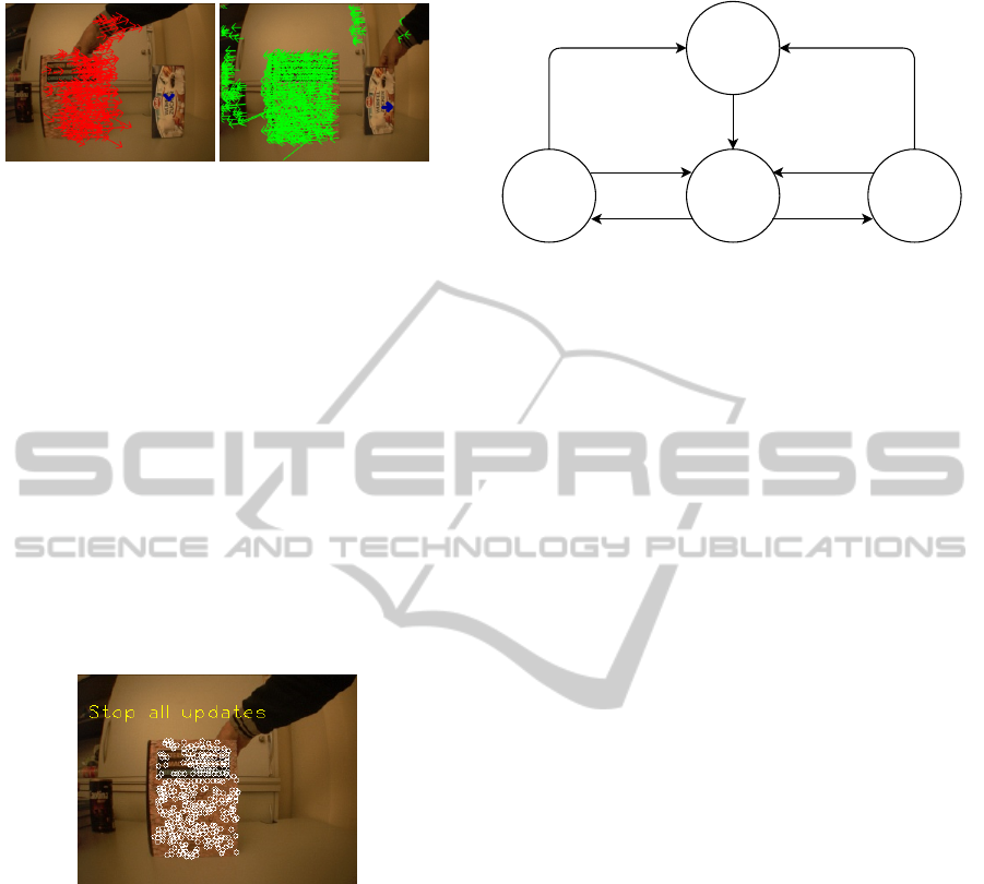
2.3 Stereo Matching and Segmentation
We find correspondences between features on left and
right images by performing a brute-force search for
best matches. The similarity between any two de-
scriptors d
(i)
and d
( j)
is calculated as their normalised
inner product and denoted S(d
(i)
,d
( j)
). Each feature
on the left image is associated with the best matching
feature on the right image if the similarity measure S
between the two descriptors exceeds a preset thresh-
old (0.9 in our case). The advantage of this brute
force approach is that it does not require calibration
of the moving cameras. Figure 4 shows an example of
stereo matching. For better visibility, matching lines
are shown for only few objects in the scene and the
saturation of the line colors are made proportional to
their corresponding stereo disparities.
HideandSeek-AnActiveBinocularObjectTrackingSystem
585

Feature extraction
Stereo matching
Temporal matching
Object centroid
estimation
Segmentation
Object centroid
Correction
Bounding box
estimation
Internal
Memory
Decision and Motor control
Object and Distractor Learning
Feature extraction
Figure 3: Block diagram of the tracking module. Rectangular boxes indicate processing units. Boxes with same color indicate
identical processes operating on different inputs. The symbol resembling a cylinder indicates a time delay of 1 frame.
We use the information about matched features for
also segmenting the objects in the scene. This is done
by clustering the matched interest points from the pri-
mary camera (left in our case) into different groups.
A greedy clustering scheme is used that starts with
a single interest point and adds new ones if their x-
position, y-position, and disparity are all within 5 pix-
els of any existing cluster member. Figure 5 illustrates
an example wherein the objects in the scene have been
clustered into different segments.
2.4 Temporal Matching
Tracking in an active vision system has to cope with
image movement due to camera motion as well as
object movement. Matching local descriptors from
frame to frame is a robust approach in such a scenario.
An image at time t is represented by a feature set
F
t
consisting of N
t
elements. Every feature element f
t
is represented by a tuple containing its Gabor descrip-
tor d
t
and its location x
t
on the image.
F
t
=
n
f
(i)
t
o
i=1:N
t
, f
(i)
t
=
h
d
(i)
t
, x
(i)
t
i
, where x = (x,y).
(1)
We find best matches between frames t − 1 and t by
brute force exhaustive search and associate every fea-
ture in the previous frame f
(i)
t−1
with a description q
(i)
t−1
that contains the index m of the best matched feature
in F
t
, the similarity s of this best match, the associated
image flow vector ∆x, and a counter n indicating the
number of times a given feature was tracked success-
Figure 4: Example of stereo matching.
fully in the past. As explained in the next section, the
features with a high count n are given higher weights
for estimating the object location. The cyan lines in
Fig. 6 illustrate the matching process from time t − 1
to t. The thinkness of the lines is proportional to the
base 2 logarithm of the count n of the correspond-
ing feature to indicate that relevant features are given
higher weights. Black lines indicate wrong matches
that have been filtered out as explained in the next
section.
2.5 Track Estimation
In this section we explain how the system efficiently
uses temporal and stereo matching information to es-
timate the object location at every frame. The part of
the system responsible for this is shaded with gray in
Fig. 3 and an example has been provided in Fig. 6 de-
picting outputs of different processing units (note the
color correspondence between the respective parts).
During tracking we estimate the object’s location
as well as its bounding box at every frame. The
bounding box of the object, which is a rectangle
placed around its centroid, is calculated using the ob-
ject segmentation information at the current frame.
The width and height of the bounding box are ob-
tained by finding the mean of absolute distances of
Figure 5: Example of segmentation based on feature prox-
imity in the image plane and in depth.
VISAPP2014-InternationalConferenceonComputerVisionTheoryandApplications
586

t-1 t
tt-1
Estimation
Correction
Figure 6: Illustration of an instance of tracking that is pro-
cessed within the gray portion of the blockdiagram in Fig 3.
Colors in this image match their corresponding processing
units (boxes) in the blockdiagram.
the segmented feature points from the current object
centroid. The size of the bounding box is averaged
over a few frames which helps in rejecting bad seg-
ments caused by momentary occlusions.
In our system, bounding box and feature matching
count provide global consistency and long term sta-
bility to the track. On the other hand, object segment
and new features provide adaptibility by adding new
information about the object.
Centroid Estimation. As illustrated in Fig. 6 an ob-
ject changes its location, scale and appearance from
time t −1 to t. We estimate the object centroid at time
t using the matched features from time t − 1 to t. We
form a set U
t−1
from the locations x
( j)
t−1
in F
t−1
that
fall on the object (see purple dots in Fig. 6) such that
U
t−1
=
n
x
( j)
t−1
∈
segment(F
t−1
)
\
BB(F
t−1
)
o
where BB is the bounding box placed around the ob-
ject centroid at t − 1.
Using the matched information we find another set U
t
in F
t
such that
U
t
=
n
x
(m( j))
t
: x
( j)
t−1
∈ U
t−1
o
where m( j) is the index of the matched feature at t for
every j at t − 1.
We now calculate the weighted median of the
matched feature locations in both x and y axis to ob-
tain the initial estimate of the centroid of the object at
time t.
ˆ
c = Median
h
x
(m(1))
t
log
n
(1)
t−1
,..., x
(m( j))
t
log
n
( j)
t−1
i
where indicates that left hand factor is weighed by
the count equal to right hand factor. The parameters
m and n are as described in section 2.4.
The estimated centroid of the object may not be its
true centroid at time t since the current segment of the
object may contain new features due to object rotation
or change in shape (if the object is not rigid). In order
to compensate for this, we first pick the right segment
of the object, segment(F
t
), at time t by choosing a
segment from the scene on which the estimated cen-
troid falls. We then estimate the true centroid of the
object as follows:
c = Median
h
x
(1)
t
,x
(2)
t
,...,x
(i)
t
i
∀x
(i)
t
∈ [segment(F
t
)
T
BB(F
t
)]
where BB(F
t
) is placed around
ˆ
c
The calculations above are done only for the pri-
mary camera. The location corresponding to c on the
other camera is obtained by using the stereo matching
information (see section 2.3). The resultant stereo lo-
cation is sent to the decision and motor control mod-
ule
2
.
3 LEARNING SYSTEM
As tracking proceeds the system learns models for
both the object as well as potential distractors. The
object model helps in the case of swift movements
and occlusions. The distractor model helps to build a
clean model for the object, to avoid distraction of the
track by other objects and to identify unusual events.
3.1 Object Learning
Tracking is susceptible to occlusions as well as
changes in object appearance. In order to help the
system track an object for long durations we learn an
object model (see also Chandrashekhariah et al. 2013)
using the same feature descriptors and the same pro-
cessing blocks that are used for the tracking scheme.
The object model should capture the stable ap-
pearance of the object rather than picking up irregu-
larities that would arise due to object occlusions. This
demands carefully choosing features that are stable.
We mark a feature on the object as eligible for enter-
ing the object model only when it has been tracked
successfully for a certain time i.e. n > γ. All those
features that enter the object model will eventually
form a feature dictionary for the object.
Dictionary for Object Modeling. The feature dic-
tionary is a buffer that has a fixed amount of memory
as shown in Fig. 7. The dictionary is initially empty
when the tracking begins. Every new feature that
enters the dictionary will enter its descriptor vector
d, location (x,y) relative to the object center and
counter k (initialized to 1). If the dictionary already
2
The motor control part uses the iKinGazeCtrl module
of the iCub to control the neck and eye coordination while
tracking (Pattacini, 2010)
HideandSeek-AnActiveBinocularObjectTrackingSystem
587

Object Dictionary
Descriptor
X
Y
1
2
N
d1
d2
dN
x1 y1
y2
x2
xN
yN
Count
k1
k2
kN
Figure 7: Object dictionary.
contains a similar feature, then the associated count
k in the dictionary is incremented. A new feature
that enters the dictionary after it gets full will flush
out the element that has the smallest value of k if
it does not match with any of the existing features
and its location (x,y). Eventually the developed
dictionary represents a model for the object. Having
a dictionary of limited size helps in continuously
evolving the model with the recent variations of the
object appearance. It also gives room for correcting
the model in case the tracking inaccuracies have
incorporated wrong features into the model.
Recognition. The recognition module is always run-
ning in the background to identify if the object has
been displaced while tracking. It uses the saved fea-
tures in the dictionary to ascertain the presence of the
tracked object in the scene. Each feature in the dictio-
nary is matched with all the features on the incoming
image to see if there is a valid match that exceeds the
preset similarity threshold (0.9 in our case) and de-
clare it as eligible for casting a vote. These eligible
features vote for the centroid location (using the (x, y)
information from the dictionary) with respect to the
location of the feature it matches on the image (see
Fig. 8). These votes are collected in a 2D space (a
matrix of image size) are smoothed using a box filter
or a gaussian filter and the global maximum is found.
The object is declared to be present in the scene if
this location contains a count higher than a suitable
threshold (10% of dictionary size in our case where
the dictionary contains 300 feature elements).
Figure 8: Object recognition.
3.2 Distractor Learning
In this work, we also develop a model for other ob-
jects in the scene considering the fact that they can
distract the tracking process and hence should be
identified. We learn short term models for only po-
tential distractors in the scene that would affect the
tracking process in the near future.
A dictionary for the distractor model is structured
in the same way as for the object dictionary but with-
out having the location information (x, y) of features.
This is because the contents of the scene as well as
their locations change continuously in an active vision
scenario making it futile to save feature locations. It
is also a challenge to selectively pick critical parts
of the scene for learning (using a dictionary of finite
size). We hence pick only those objects or parts of the
scene for learning that are likely to occlude the object
shortly.
Let c
L
and x
i
L
be object centroid and feature lo-
cation respectively (on the left camera). The vector
c
L
− x
i
L
indicates the distance vector from the fea-
ture to the object centroid whose euclidean distance
D
i
= kc
L
− x
i
L
k. Let ∆c
L
and ∆x
i
L
be object and fea-
ture flow vectors respectively. The relative flow vec-
tor of a feature with respect to the object will then be
∆x
i
L
− ∆c
L
which indicates motion in one time frame.
We calculate the distance component of the relative
feature flow vector along the direction of distance
vector which is given by :
∆D
i
=
∆ x
i
L
− ∆ c
L
, c
L
− x
i
L
kc
L
− x
i
L
k
.
The sign of the term ∆D
i
indicates the direction of
motion of the feature. The time taken by a given fea-
ture at x
i
L
to reach the object centroid in the image
plane is given by :
τ =
D
i
|
∆D
i
|
× f ps
,
where f ps is the speed of the algorithm in frames per
second.
The features that are going to occlude the object in
less than 5 seconds are considered critical and up-
dated to the distractor model (see Fig. 9a). However,
features of the objects that are moving away from
the object (when ∆D
i
is negative) are not considered
harmful for tracking and hence they are neglected (see
Fig. 9b).
Distractors in the scene that are behind the object by
a considerable depth are neglected, i.e. the following
disparity condition should be satisfied for a positive
value of δ.
(c
L
(x) − c
R
(x)) −
x
i
L
(x) − x
i
R
(x)
> δ ∀i
VISAPP2014-InternationalConferenceonComputerVisionTheoryandApplications
588
(a) (b)
Figure 9: Distractor model update example : (a) Features
that are included in the model. (b) Features that are not
included in the model.
However, distractors in the front are considered
a threat irrespective of their position between the
camera and the object.
In addition, self occlusion of the object is also
neglected by not considering the features belonging
to the object (i.e. ∈ segment(F
t
))
Distractor Recognition. A Distractor in the scene is
recognized using the distractor dictionary in the same
manner as that of object recognition. However, the
features will vote for their absolute locations rather
than for the centroid. The presence and location of
the distractor is decided by merely calculating the
density of the distractor’s features that are overlap-
ping/masking the tracked object (see Fig. 10).
Figure 10: Distractor recognition.
4 SYSTEM STATES
The system goes into different states as shown in
Fig. 11 depending on inputs received from tracker and
recognition (object and distraction). This will further
guide the decision module of the architecture (Fig. 2).
The system primarily contains four states, each of
which changes to the other based on events. An event
is a logical combination of outputs of different parts
of the system namely - tracking, object recognition
and distractor recognition (see Table 1). Each of these
parts is associated with two quantities - output status
(true/false) and output location.
1. Initialize. The system is initialized with an object
that is in the center and close to the stereo cam-
Initialize
Search
Track
Pause
Hidden
Lost
In focus
Time out
Time out
Discovered
Revealed
Figure 11: States of the system.
eras. When an object is brought in the region of
focus the system triggers and starts tracking it.
2. Track. This is the normal state of the system un-
less the object is lost or hidden. When the user
displaces the object to a different location in the
scene with swift movements the object recogni-
tion helps in restoring the track.
3. Pause. The system goes to a pause mode when
the object is masked by a moving occluder or the
object moves behind an occluder. This is known
when the tracker location overlaps with a patch P
that is identified as an occluder by the distrac-
tor model i.e. when (c ∈ P), concurrently there
is no output from the object recognition (R = 0).
The tracking resumes when the object is revealed
again (R = 1).
4. Search. System starts searching when the object
is lost i.e. when the user moves it out of the scene.
When an object suddenly disappears or when a
distractor suddenly masks the object, the focus of
the cameras in depth shifts drastically from on ob-
ject to either behind or front, again followed by
no output from the object recognition within the
scene purview, i.e. when T = 0 and R = 0. A
random search is then initiated in the direction in
which the object was lost until it is discovered us-
ing recognition output. All the model updates are
stopped in this state as well as the pause state.
5 SYSTEM EVALUATION
Performance evaluation of object tracking often re-
quires ground truth information of the object as in the
case of prerecorded images/videos (Yin et al., 2007).
However, this information is not easily available in a
realtime active vision system. There are other algo-
rithms in the literature that use no ground truth infor-
mation but spatial and temporal differences of object
cues with respect to its surrounding as an alternative.
HideandSeek-AnActiveBinocularObjectTrackingSystem
589
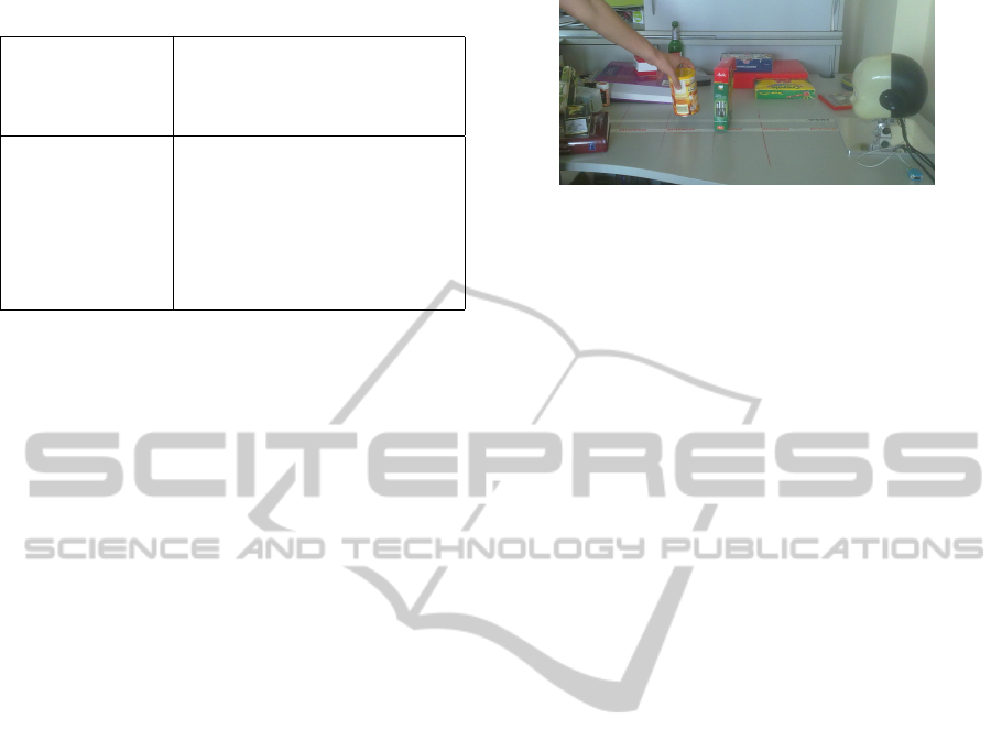
Table 1: System states and events.
System Output
Tracker Status T(1/0), Centroid c
Object Model Recognition R(1/0), Location l
Distractor Model Occluded O(1/0), Patch P
Events Combination
In focus Object is in center and close
Displaced R=1 ∧ kl − ck > T hreshold
Masked/Hidden O=1 ∧ R=0 ∧ c∈P
Revealed O=1 ∧ R=1
Lost T=0 ∧ R=0
Discovered T=0 ∧ R=1
This is again used only in the case of self occlusions
but not for occlusions from other objects in the scene
(Erdem et al., 2004). In order to keep the evaluation
procedure simple for unusual active binocular track-
ing setting we are using, we evaluate our system in a
staged manner by comparing performance of the par-
tial system with the full system in different scenarios.
5.1 Experimental Setup
We conduct our experiment on the iCub robot head in
a regular office room with cluttered background (see
Fig. 12). We collect various objects such as a coffee
cup, tea packet, coke tin, books etc that have sufficient
texture on them. We ask a subject unfamiliar with
the system to test the algorithm while we count the
success and failure rates for various scenarios:
1. No Occlusion Scenario. In this case the object
moves in front of a cluttered background making
changes in the scale and in-plane/in-depth rotation
of the object. The algorithm is mainly tested for
three cases:
• Displacement. Swift and erratic movements of
the tracked object.
• Distraction. Bringing another object next to the
object in focus and push it or move them to-
gether
• Merging: Moving the object far away from the
robot and merging it with the background for a
significant amount of time.
2. Severe Occlusion Scenario. In this case the object
is completely occluded by other objects. The ob-
ject is either occluded by another object (masking)
or the object goes behind an occluder (hiding). We
further consider two scenarios:
• Momentary Occlusions. We occlude the object
for a short time of the order of 2 to 5 seconds.
• Long-term Occlusions. We occlude the object
for a long time of the order of 10 to 30 seconds.
Figure 12: An instant of the experiment wherein an object
is hiding behind an occluder.
3. Object disappearance scenario: In this case the
object is suddenly moved out of the scene to see if
the system can search and discover the lost object.
5.2 Performance Quantification
We conducted two day long experiment (comprising
345 trials in all) and performance was quantified for
various scenarios.
No Occlusion. We initially compare a partial system
having no learning modules with the full version
of the system, for the no occlusion scenario. Since
there are no complete occlusions the distractor model
would not add much improvement to the performance
and hence it is ignored. We ask the subject to
randomly select 3 objects and make 5 trials for each
of the above cases (90 trials in all). We count the
number of trials in which tracking was successful
throughout the sequence. The percentage of success
is listed in Table 3. We observe that the performance
of the system improves by incorporating learning that
rectifies inaccuracies of the tracker. It particularly
helps in the case of merging. Since in our system the
object segment evolves over time, the system would
gradually fail when the object is merged with the
background for significant amount of time. This can
be avoided to a good extent by introducing learning.
Occlusion. We then test the system in the occlusion
scenarios wherein we compare the system containing
object learning alone with the full system also
containing the distractor model. We ignore the
partial system without learning in this case since it is
bound to fail in case of complete occlusions. Table 3
lists the performance in terms of Precision that is
calculated as T P/(T P + FP) where T P and FP are
true and false positives respectively. FP originates if
the system mistakes the occluder for the object. The
numbers listed in the table are averaged over 30 trials
(5 for each of 6 objects with different occluders; 240
trials in all).
We observe that the precision gets better with the
disctractor model since it helps the system to stop
VISAPP2014-InternationalConferenceonComputerVisionTheoryandApplications
590

Table 2: Performance evaluation : No occlusion scenario.
No learning Full system
Displacement 53% 73%
Distraction 86% 93%
Merging 0% 80%
Table 3: Performance evaluation : Occlusion scenario.
No distractor
learning
Full system
Occlusions Mask Hide Mask Hide
Momentary 90% 66% 100% 96%
Long-term 63% 60% 90% 73%
updating the object model when it is occluded.
This is even more evident in the case of long-term
occlusions. We also observe that the performance
for masking is better than hiding because of object
perspective change, camera jitter etc. Any mistake in
the distractor identification would harm the system
more in the case of long term occlusions.
Searching. In the end, we also test the searching per-
formance when the object is lost. We count how many
times the object was discovered in less than 30 sec-
onds. We observed that the searching was successful
in 73% of the trials (15 in all).
The tracker performance recorded as a video
can be viewed at https://fias.uni-frankfurt.de/neuro/
triesch/videos/icub/tracking/.
6 CONCLUSIONS
We developed and demonstrated an active stereo-
vision based tracking system on the robot. In con-
trast to other systems in the literature, our system at-
tempts to identify unusual events in the scene and take
necessary actions. The system is also generic enough
to be applied for applications such as face/pedestrian
tracking on static/active cameras (an instance of face
tracking is shown in Fig. 13). There is a scope for fur-
ther improvement in every part of our system. How-
ever, the present system clearly demonstrates how ob-
ject and distractor models allow to recognize difficult
Figure 13: An instant of face tracking.
tracking situations and to respond to them appropri-
ately. This brings us one step closer to building track-
ing systems with human level performance.
ACKNOWLEDGEMENTS
This work was supported by the BMBF Project
“Bernstein Fokus: Neurotechnologie Frankfurt, FKZ
01GQ0840”. We thank S
´
ebastien Forestier for the
participation and help with the experiments.
REFERENCES
Chandrashekhariah, P., Spina, G., and Triesch, J. (2013).
Let it learn: A curious vision system for autonomous
object learning. In VISAPP.
Erdem, C., Sankur, B., and Tekalp, A. (2004). Performance
measures for video object segmentation and tracking.
Image Processing, IEEE Transactions on, 13(7):937–
951.
Falotico, E. and Laschi, C. (2009). Predictive tracking
across occlusions in the icub robot. In Humanoid
Robots, 2009, pages 486–491.
Ginhoux, R. and Gutmann, S. (2001). Model-based object
tracking using stereo vision. In ICRA, Volume: 2, cole
Nationale Suprieure de Physique de.
Kalal, Z., Mikolajczyk, K., and Matas, J. (2012). Tracking-
learning-detection. Pattern Analysis and Machine In-
telligence, IEEE Transactions on, 34(7):1409–1422.
Nelson, R. C. and Green, I. A. (2002). Tracking objects
using recognition. In In International Conference on
Pattern Recogntion, pages 1025–1030. Prentice Hall.
Pattacini, U. (2010). Modular Cartesian Controllers for
Humanoid Robots: Design and Implementation on the
iCub. Ph.D. dissertation, RBCS, IIT, Genova.
Rosten, E. and Drummond, T. (2006). Machine learning for
high-speed corner detection. In ECCV, pages 430–
443.
Ta, D., Chen, W., Gelfand, N., and Pulli, K. (2009). Surf-
trac: Efficient tracking and continuous object recogni-
tion using local feature descriptors. In CVPR09.
Triesch, J., Ballard, D. H., and Jacobs, R. A. (2002). Fast
temporal dynamics of visual cue integration. Percep-
tion, 31(4):421–434.
Wiskott, L., Fellous, J., Kr
¨
uger, N., and v.d. Malsburg,
C. (1997). Face recognition by elastic bunch graph
matching. IEEE Trans. Pattern Anal. Mach. Intell.
Yin, F., Makris, D., and Velastin, S. A. (2007). Perfor-
mance Evaluation of Object Tracking Algorithms. In
PETS2007.
HideandSeek-AnActiveBinocularObjectTrackingSystem
591
